Torrent BW900 User manual
P a g e 1 | 24
WATER/MEDIA BASED BLAST CLEANING MACHINE
MODEL BW900 / BW1250
USER MANUAL
English version
Version 1, July 2021
WETBLAST

P a g e 2 | 24
TABLE OF CONTENT
1. INTRODUCTION ………………………………………………………………….………3
2. SYMBOLS USED …………………………………………………………………….…….3
3. DESIGNATION OF MANUFACTURER AND MACHINERY …...………….4
4. EC DECLARATION OF CONFORMITY………………………….….………….....5
5. GENERAL DESCRIPTION OF THE MACHINERY ………….…….…..……….7
6. SAFETY INSTRUCTIONS ………………………………………….…….….……..…11
7. PRE-INSTALL CHECKS ……………………….………………….…………..……….12
8. INSTALLATION …………………..……………………………….……………………..13
9. MACHINE PARTS ………………………………………………………………….……16
10. OPERATING INSTRUCTIONS ……………………….…………………………….19
11. MAINTANANCE OF MACHINE ……….………………………………………….20
12. TROUBLE SHOOTING ………..….…………………………………………….......22
13. SPECIFICATIONS ………………..……………………………………………..……..34
14. ELECTRICAL DRAWING ……………………………..……………………………..24
15. SPARE PARTS …………………………………..……………………………………...25
P a g e 3 | 24
1. INTRODUCTION
The purpose of this manual is to provide important information concerning the Wetblast parts
cleaning washer machine to ensure safe use of the equipment.
Before working with the machine, please read these instructions, as well as the information sheet
and labels of the chemical supplies necessary for the use of the Wetblast machine. This instruction
manual should be placed near the machine.
NOTE: Attempting to operate this equipment without reading this manual will likely cause the
equipment to fail and may void the warranty.
2. SYMBOLS USED
NOTE: The note symbol refers to instruction regarding the equipment. Failure to follow them could
damage the equipment or effect its ability to operate properly.
The safety alert symbol gives notice of general danger, you must be attentive and alert, for your
safety is involved.
CAUTION: Gives notice of general danger. Omission of given procedure could end in personal injury
or damage of property
WARNING: Gives notice of general danger. Omissions of given procedure could end in serious
personal injury or death.
DANGER: Gives notice to general danger. Omission of given procedure WILL end in personal
Injury or death.
Gives notice of danger of injury by electricity.
Gives notice of operator’s duty to look up appropriate information in the instruction manual before
using the machine.
Gives notice of operator’s duty to wear protective gloves.

P a g e 4 | 24
3. DESIGNATION OF MANUFACTURER AND MACHINERY
Manufacturer:
Blastwash UK - A division of NCH (UK) Ltd, 24 Baron Avenue, Earls Barton, Northampton, England,
NN6 0JE
Flexfill s.r.o. - Siřejovická 1213, 412 01 Lovosice, Czech Republic
Represented by:
BLASTWASH UK –A DIVISION OF NCH (UK) 24 Baron Avenue, Earls Barton, Northampton , England,
NN6 0JE
UK: NCH (UK) Ltd., Arrowmere House, Springvale Ave., Bilston, WV14 0QL, United Kingdom
Ireland: NCH Ireland Ltd, The Brewery Business Park, Ardee Road, Dundalk, County Louth., Ireland
Australia: NCH Australia, 5-9 Ralph Street, Alexandria NSW 2015
USA: NCH Corporation, 2727 Chemsearch Blvd., Irving, TX 75062
Designation of machinery:
Wetblast water/media based parts cleaning system
Model 900 / 1250
P a g e 5 | 24
4. EU DECLARATION OF CONFORMITY
EU Declaration of Conformity
In accordance with European Parliament and CouncilDecision No 768/2008/EC Annex III
1. Product model / product:
Product
Wet Blaster
Model/type
BW 900/1250/1500 WB
Batch/serial no.
2. Manufacturer
Name
Blast Wash UK Ltd
Address
24 Baron Avenue, Earls Barton Industrial Est, Northampton.
NN6 0JE. UK.
3. This declaration is issued under the sole responsibility of the manufacturer.
4. Object of the declaration:
Product
Wet Blast Cabinet
Specification
Wet blaster glove box cabinet with abrasive fluid hose applicator and
post blasting rinse off hose. Internal Cabinet Size is W900mm x
D1070mm x H945mm. Abrasive fluid distributed with a minimum flow
rate 900 l/m and pressure 10 bar.

P a g e 6 | 24
5. The object of the declaration described above is in conformity with the relevant Union
harmonisation legislation:
2006/42/EC
The Machinery Directive
2014/30/EU
The Electromagnetic Compatibility Directive
2011/65/EU
The Restriction of Hazardous Substances Directive
6. References to the relevant harmonised standards used or references to the other
technical specifications in relation to which conformity is declared:
Reference & Date
Title
EN 1248:2001
+A1:200
Foundry machinery - Safety requirements for abrasive blasting equipment
EN ISO 14877:2002
Protective clothing for abrasive blasting operations using granular abrasives
EN 12921-1:2005
+A1:2010
Machines for surface cleaning and pre-treatment of industrial items using
liquids or vapours - Part 1: Common safety requirements
EN 60204-1:2018
Safety of machinery. Electrical equipment of machines. General requirements
EN 61000-6-2:2019
Electromagnetic compatibility (EMC) Part 6-2: Generic standards Immunity for
industrial environments
EN 61000-6-4:2019
Electromagnetic compatibility (EMC) - Part 6-4: Generic standards - Emission
standard for industrial environments
7. Additional information:
The technical documentation for the machinery is available from the manufacturer
above.
Signed for and on behalf of:
Blast Wash UK Ltd
Place of issue:
Northampton, UK.
Date of issue:
31st July 2020
Name:
Mr Nick Wordingham
Function:
Managing Director
Signature:

P a g e 7 | 24
5. GENERAL DESCRIPTION OF THE MACHINERY
The Wetblast machine is water and media based cleaning machine that combines the joint action of
the water, media, detergent and compressed air used to accelerate the water and media to clean,
degrease, polish and remove corrosion from parts.
The Wetblast machine is designed for cleaning, degreasing and surface preparation of a wide variety
of parts depending on the media that is used in the machine. Do not use the machine for a different
purpose other than that specified by your application when purchasing/renting the machine.
NOTE: With the Wetblast, use only Storm Metal Guard, a rust inhibitor and media specified by the
manufacturer. Use only degreasing agents and media recommended and approved by the
manufacturer.
The part is loaded into the machine and placed on the work bed to be cleaned/blasted. The water
and media is mixed and pumped to the blast nozzle at the end of a flexible hose, compressed air is
also used to accelerate the impact of the water and media. This process is activated via a foot switch
which engages the pump and air solenoid and allows the user to direct the high-pressure
water/media based cleaning agent towards the part to be cleaned. There is also a water rinse off
gun to help rinse off the media from the cleaned parts, this is pumped from a closed loop tank air
operated pump through a trigger operated hand gun. There is a filter paper used on the closed loop
tank to help reduce contamination. The machine uses two LED lights for better visibility by the user
during operation. There is a wiper on the viewing screen and a screen wash pipe to allow clean
filtered water to assist in keeping the screen clean during blasting. There is a needle valve on the
machine to set the desired amount of water for the screen wash.
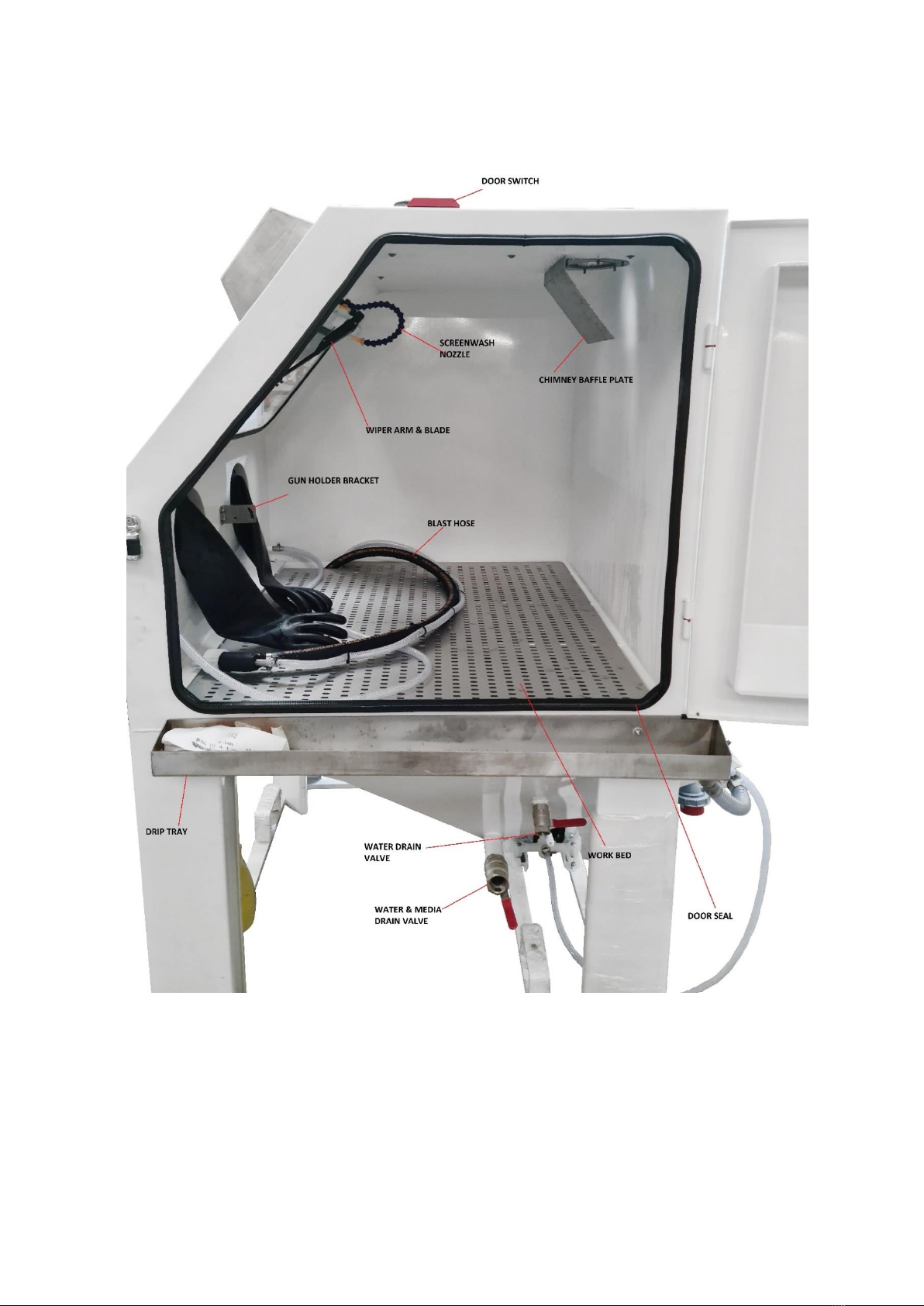
The blast area is concealed within the machine and is fitted with a door interlock for the users
safety. There are two/four integrated gloves on the respective ports which allow the handling of the
blast gun and the components being cleaned and protects the users hands from the cleaning agent
and abrasive and other waste. In order to keep the accumulation of media and dirt on the work bed
and walls it is advisable to use the rinse gun to wash down the inside of the machine.
There is a small switch control panel on the front of the machine which has the light on/off switch,
reset button and the emergency stop button. There is also a pressure gauge and pressure regulator
on the left leg. The pressure gauge is used to adjust the working pressure depending on what finish
is desired, normal operating pressure is 4 bar.
In the bottom of the machine below the work bed is the pump housing and agitation nozzle. When
the pump is activated it pumps water through a T piece which sends the slurry mix to the blast gun
and the agitation nozzle, the agitation nozzle stirs the water and media so the correct mix gets to the
blast gun.
An electrical box is on the back of the machine. There is a lockable isolator on the electrical panel.
Once the main isolator is switched on the rest of the machine is controlled through the small control
panel on the front right leg of the machine. The mains isolator must be in easy reach of the operator
at all times.
P a g e 8 | 24
There is drain valve on the right side of the hopper, upper valve is used for draining water only and
lower valve is for water and slurry.
On the left side of the hopper is a ball valve which is used for manual agitation, This would be used if
the machine hasn’t been used for a period of time, the valve would be opened for a few seconds to
help stir up the media.
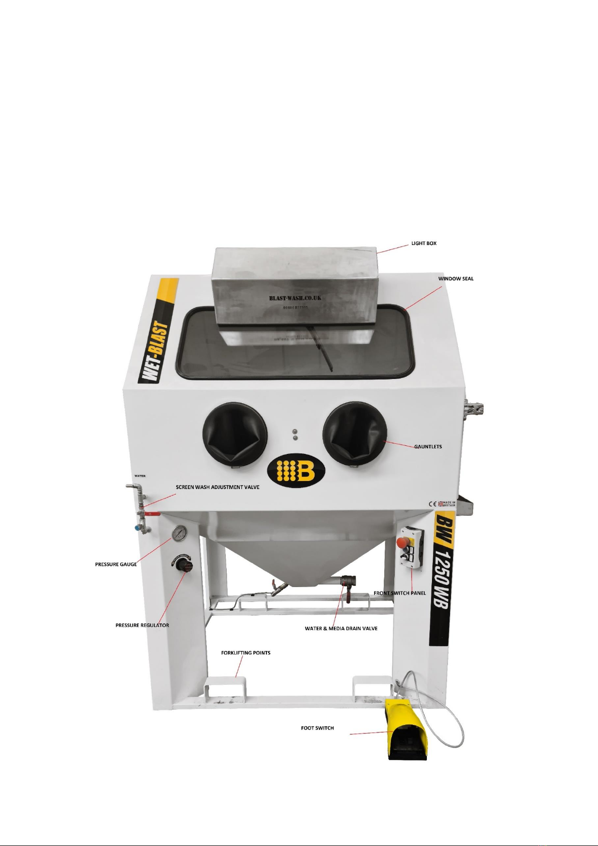
FRONT VIEW OF BW1250 WETBLAST CLEANING MACHINE

P a g e 9 | 24
REAR VIEW OF THE BW1250 WETBLAST, 415V 3 PHASE ELECTRICAL PANEL
ELECTRICAL PANEL
CHIMNEY
PUMP MOTOR
OWERFLOW PIPE
32 AMP PLUG
P a g e 10 | 24
INTERNAL VIEW OF BW1250 WETBLAST

P a g e 11 | 24
6. SAFETY INSTRUCTIONS
If you feel the equipment has been damaged or is in an unsafe condition, inform your supervisor and
wait until the issue is resolved before using the equipment. If necessary, contact the manufacturer
or an authorized representative in order to repair the damage.
IMPORTANT SAFETY INSTRUCTIONS - SAVE THESE INSTRUCTION!
WARNING: When using this product basic precautions should always be followed, including the
following:
1) Read all instructions before using the product
2) To reduce the risk of injury, close supervision is necessary when a product is used near
children.
3) Know how to stop the product and bleed pressures quickly. Be thoroughly familiar with the
controls.
4) Stay alert –watch what you are doing.
5) Do not operate the product when fatigued or under the influence of alcohol or drugs.
6) Keep operating area clear of all persons.
7) Do not overreach or stand on unstable support. Keep good footing and balance at all times.
8) Follow the maintenance instructions specified in the manual.
9) Read the INSTALLATION section for important electrical instructions including how to swap
the electrical phase in the plug.
WARNING: Check the power supply cords of this appliance at regular intervals for damage. If the
supply cords are found to be damaged, contact the manufacturer or an authorized representative in
order to repair the damage.
This machine must be connected to a properly grounded 3 phase and neutral power supply. Check
the label on the electrical box (Rear of machine) to ensure correct voltage and protection has been
provided. Before carrying out any work on the electrical equipment, ensure the machine is isolated
from the electrical supply.
CAUTION: Depending on frequency and type of use, the floor around the wet blast may become
slippery. It is therefore mandatory to assess the need to fit anti slip mats around the machine.
CAUTION: The machine must be sited on a suitable firm level floor.
CAUTION: The machine must be sited on a suitable firm level floor.
WARNING: Do not use the Wetblast electrical supply to power any other equipment/machines
WARNING: Do NOT use outside / in damp conditions (this machine is for indoor use only)
CAUTION: Install and use the machine in a ventilated area, free of flammable liquids or gases.

P a g e 12 | 24
WARNING: Always ensure the overflow from machine to the closed loop tank is clear and free
blockages, a blockage in this can cause water ingress into the pump motor causing failure of the
motor.
WARNING: Do not operate any electrical equipment inside the unit. Do not use the machine near
sparks, a flame or fire source, or any other source of heat. Do not open any electrical part of
machine.
DANGER: Do not contaminate cleaning solution with any flammable material. Make sure parts to be
cleaned are free of any flammable material before placing them in the Wetblast and drain if
necessary. Do not add solvents or liquids, e.g. paint thinners, petrol, hydrocarbon solvents or
chlorinated solvents.
Read and understand all the safety instructions below before you use or install the Wetblast
machine. This manual should be kept so that it can be used in the future, either for training of new
users or for consultation of regular or occasional users.
Customers and users should always consider safety when operating machinery of any kind. Carry out
regular workplace safety assessments, implement and follow all relevant safety procedures.
7. PRE-INSTALL CHECKS
Before proceeding with the installation, please check that the following pre-requirements are met at
the location of the machine:
-A 415V 32A 3 phase neutral and earth supply, or 230VAC 32A (depending on unit
configuration), single phase, 50 or 60 Hz power supply having an earthed neutral conductor.
The 3 phase machine will come with a 3m cable with a 32A 5 pin phase rotation plug
prewired; the single phase machine will have a 3m lead with a 32A 3 pin plug prewired. The
power supply must be located in the installation area and within reach of the Wetblast
approx. 3 metres.
-A min. 900 l/min (35 cfm), 3 to 8 bar (45 to 145 PSI) dry and oil-free compressed air intake
that can be directly plugged into the machine. This airline should be from a secondary airline
source, and not a primary lead used for other tools or equipment. There must be no
restrictions in the line or pcl quick release couplings as these will restrict the cfm. The
minimum inner bore of the pipe must be 12.5 mm inner bore. A ½” BSP female ball valve will
be needed to connect the air supply from the machine to.
-There will need to be a water tap near the machine to fill the machine sump and closed loop
tank.
If these requirements are not met, the installation cannot be completed.

P a g e 13 | 24
The Wet Blast machine is available in single or three phase electrical specification, depending on
your option please ensure that you have the correct isolator ready for the installation engineer.
The machine will require a half inch BSP air supply with an air tap as shown in
the picture.
The air supply and the electrical supply will need to be in place before we deliver and
install as any delays due to these not being in place may incur extra charges.
CHECK LIST:
½” BSP BALL VALVE FOR THE AIR SUPPLY
½” BSP BALL VALVE OR WATER TAP FOR WATER SUPPLY
32 AMP 5 PIN FEMALE POWER SOCKET CONNECTED TO YOUR SUPPLY
HOSE PIPE NEAR MACHINE TO FILL MACHINE AND CLOSED LOOP TANK
FORKLIFT TRUCK TO UNLOAD MACHINE.
8. INSTALLATION
Installation of the machine should only be performed by manufacturer’s personnel or personnel
with appropriate authorization from the manufacturer.
CAUTION: The WETBLAST cleaning machine should be placed on a horizontal and level surface in a
ventilated area, free of flammable liquids or gases. There are forklift lifting points on the machine for
moving and positioning the machine. Once installed, do not move or transport the machine without
the supervision of manufacturer’s personnel or an authorized representative.
PLACING THE MACHINE
Remove packaging from machine. Be careful not to damage the machine if using a knife to remove
the packaging.
Once the packaging has been removed:
P a g e 14 | 24
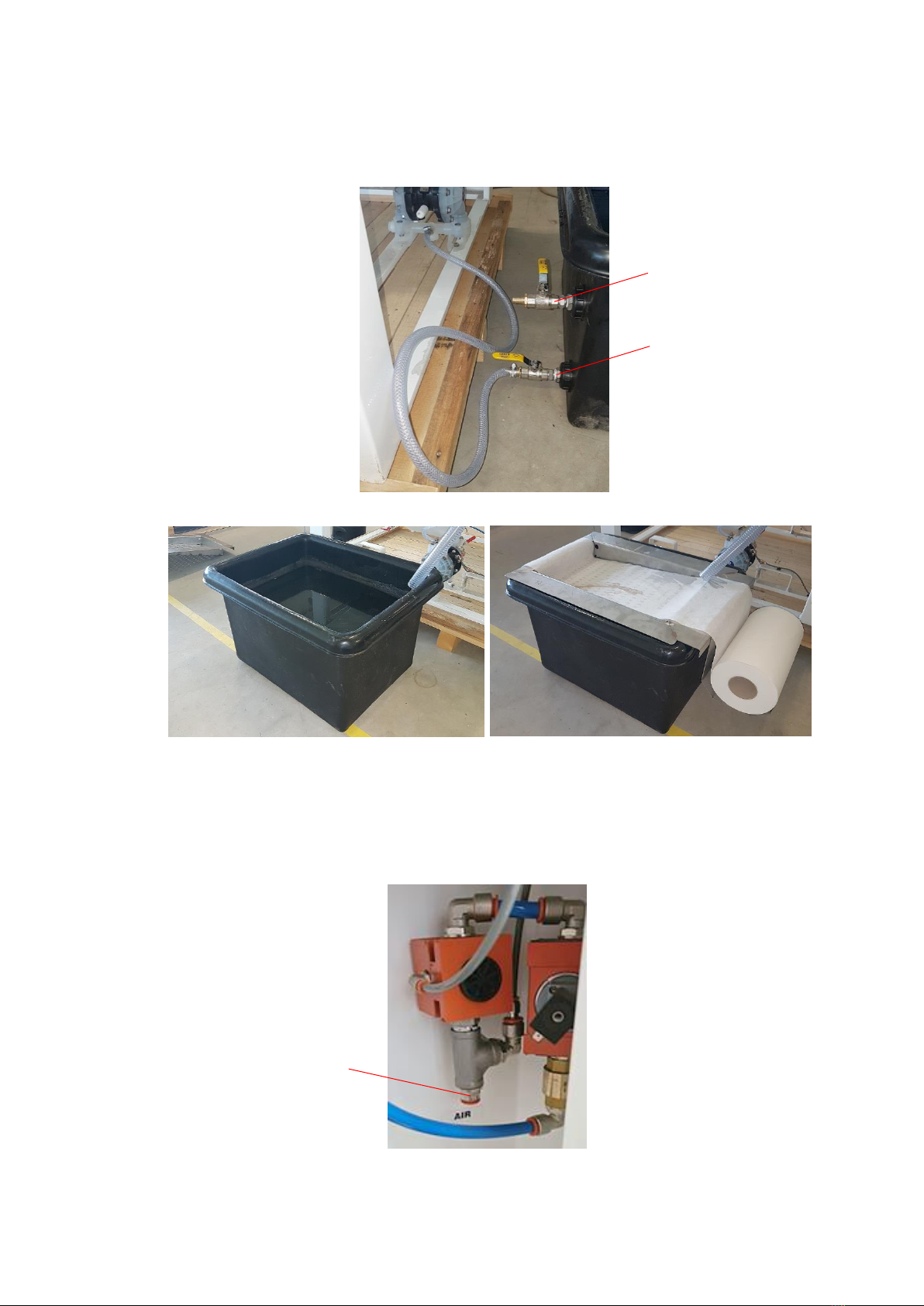
Remove the closed loop tank from inside the machine and place at the rear of the machine
under the overflow pipe.
Connect the clear hose from the lower connection on closed loop pump and connect to
lower ball valve on tank.
Fill closed loop system with 135 ltrs water –approx. under upper valve
Closed loop system: Assemble metal parts according to the picture, and put a filter paper on.
Add 100 ltrs of water to machine tank for WB900 and 140 ltrs for WB 1250 –approx. until
water starts to leak from overflow pipe (page 9).
Add 0.5 ltr Storm Metal Guard.
Add one bag of media (glass bead).
Connect air hose from air supply on left leg to customers air supply. 12 mm pipe, 3 metre
length to ½” BSP connector.
Plug in to 3 phase/single phase (depending on unit) power supply.
OVERFLOW CONNECTION
CONNECTION TO CLOSED
LOOP PUMP
AIR CONNECTION

P a g e 15 | 24
Turn on the mains switch.
Check phase rotation in control panel –green correct, orange need to change.
If phase rotation wrong, disconnect electrics and change rotation with screwdriver and
reconnect (see pictures below).
PHASE DETECTION UNIT AND PHASE ROTATION PLUG
When the machine is plugged
in if the green light is showing
on D1 phase detection unit the
machine is ready to go.
When the machine is plugged in
if the green and orange light is
showing the phase is incorrect
and needs swapping on the
plug. Otherwise the pump will
not work
If the orange is on D1 relay
rotate the plug pins as shown
above. This will swap the
electrical phase and turn the
orange light off.
Close electric box door.
Press reset button on control panel.
Open water valve on left to run water on window.
Adjust water pressure on window if necessary.
Set pressure regulator to 4 bar working pressure with foot on pedal.
P a g e 16 | 24
9. MACHINE PARTS
CONTROLS FOUND ON THE FRONT OF THE BW1250 WEBLAST MACHINE
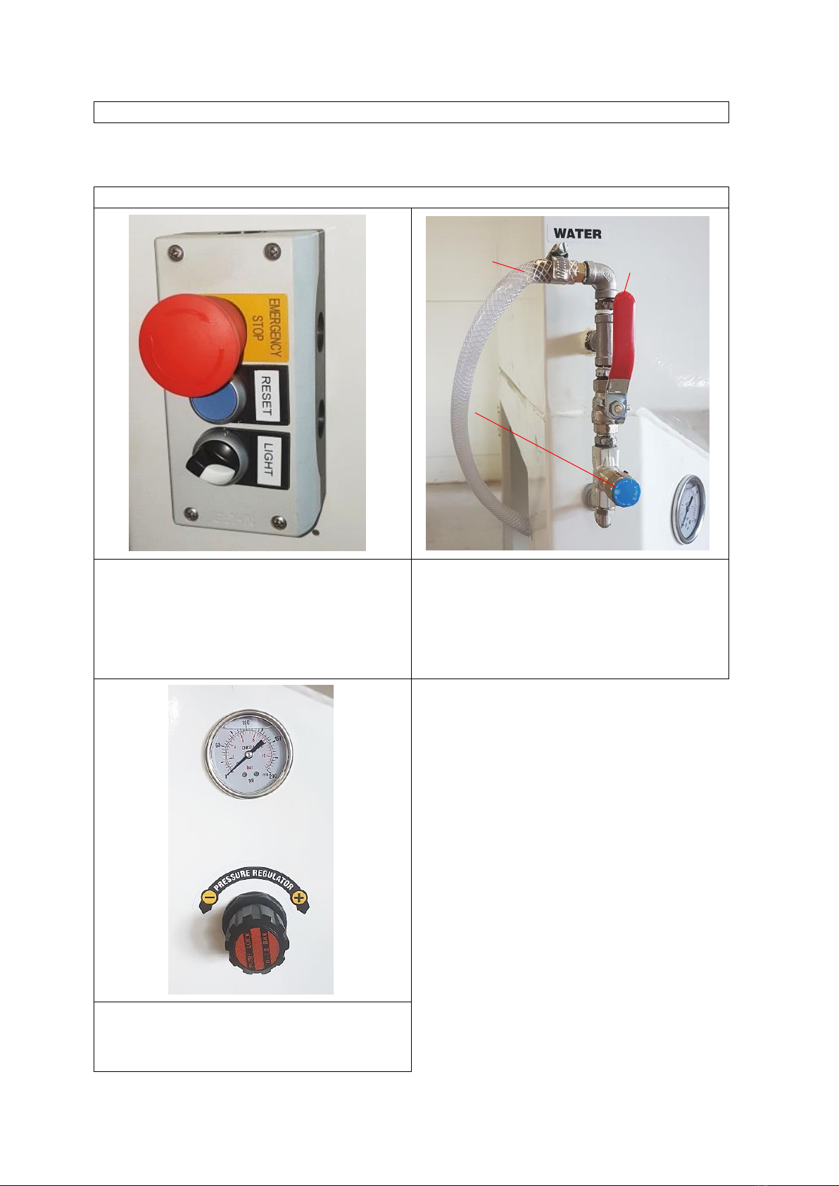
Front switch panel consists of the emergency
stop button, reset button and the light switch.
As an extra safety feature on the machine the
reset button must be pressed every time the
door is closed after loading the parts into the
machine.
The water from the closed loop tank is pumped
to the screen wash valve, there is a fine
adjustment valve to adjust the flow rate to the
wiper wash. It is important to use the screen
wash to prolong the life of the viewing glass.
Pressure regulator is used to control the impact
velocity of the media/water 4bar is normal
operating pressure.
WATER CONNECTION
FOR OPEN LOOP
MACHINES
SCREEN WASH
WATER ON/OFF
VALVE
SCREEN WASH FINE
ADJUSTMENT
VALVE
P a g e 17 | 24
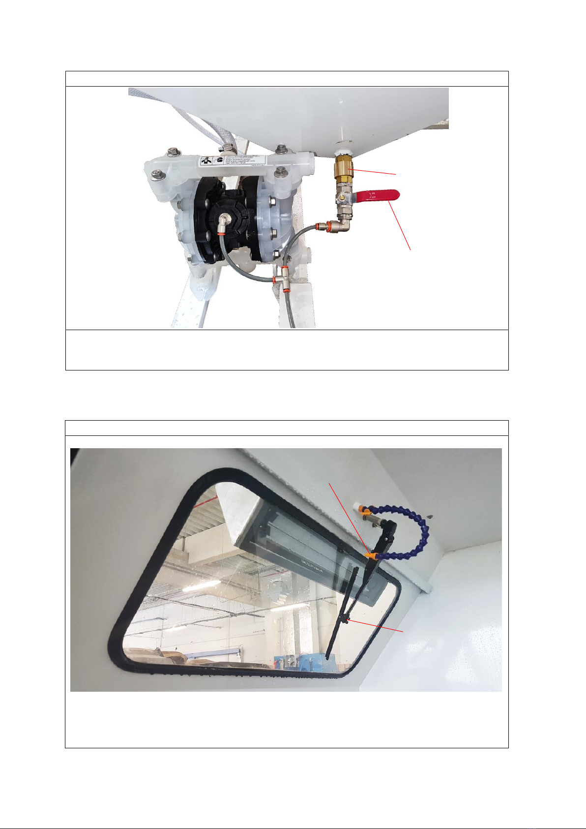
CLOSED LOOP AIR PUMP AND MANUAL AGITATION VALVE
Closed loop pump pumps the water from the closed loop tank to the screen wash hose and the
rinse off gun. The manual agitation valve is used to stir the tank if the machine hasn’t been used
for a period of time.
WIPER ARM, WIPER BLADE, SCREEN WASH NOZZLE
SCREEN WASH NOZZLE
WIPER ARM AND BLADE
NON RETURN VALVE
MANUAL AGITATION VALVE
P a g e 18 | 24
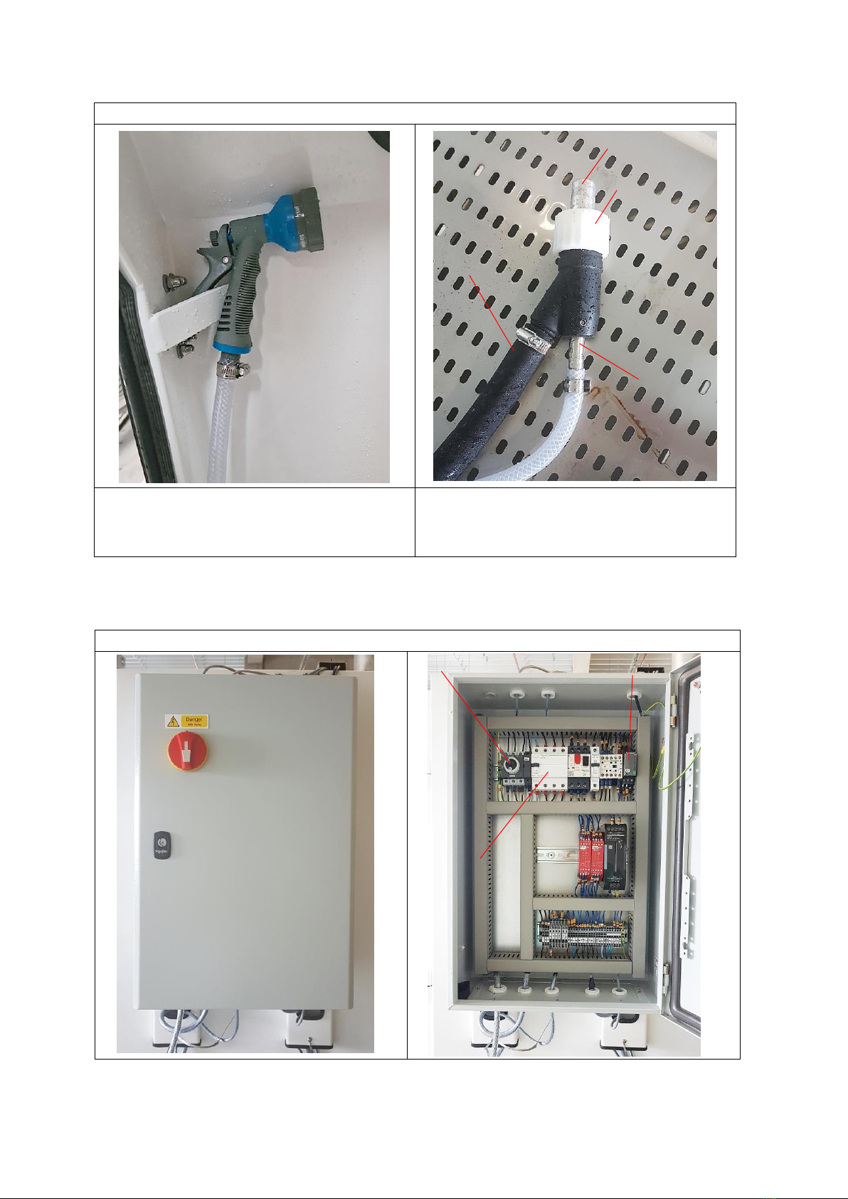
RINSE OFF GUN/ BLAST GUN
Rinse offgun used to clean the component
after the blasting process, the water for this is
fed from the closed loop tank.
The blast gun. The water and media is pumped
and accelerated to the blast gun using a motor
driven pump and compressed air.
ELECTRICAL BOX / INTERNAL VIEW
AIRJET
BLAST HOSE
BLAST NOZZLE
NOZZLE RETAINING
RING
MAIN SWITCH
RESIDUAL CURRENT
DEVICE
PHASE DETECTION UNIT
P a g e 19 | 24
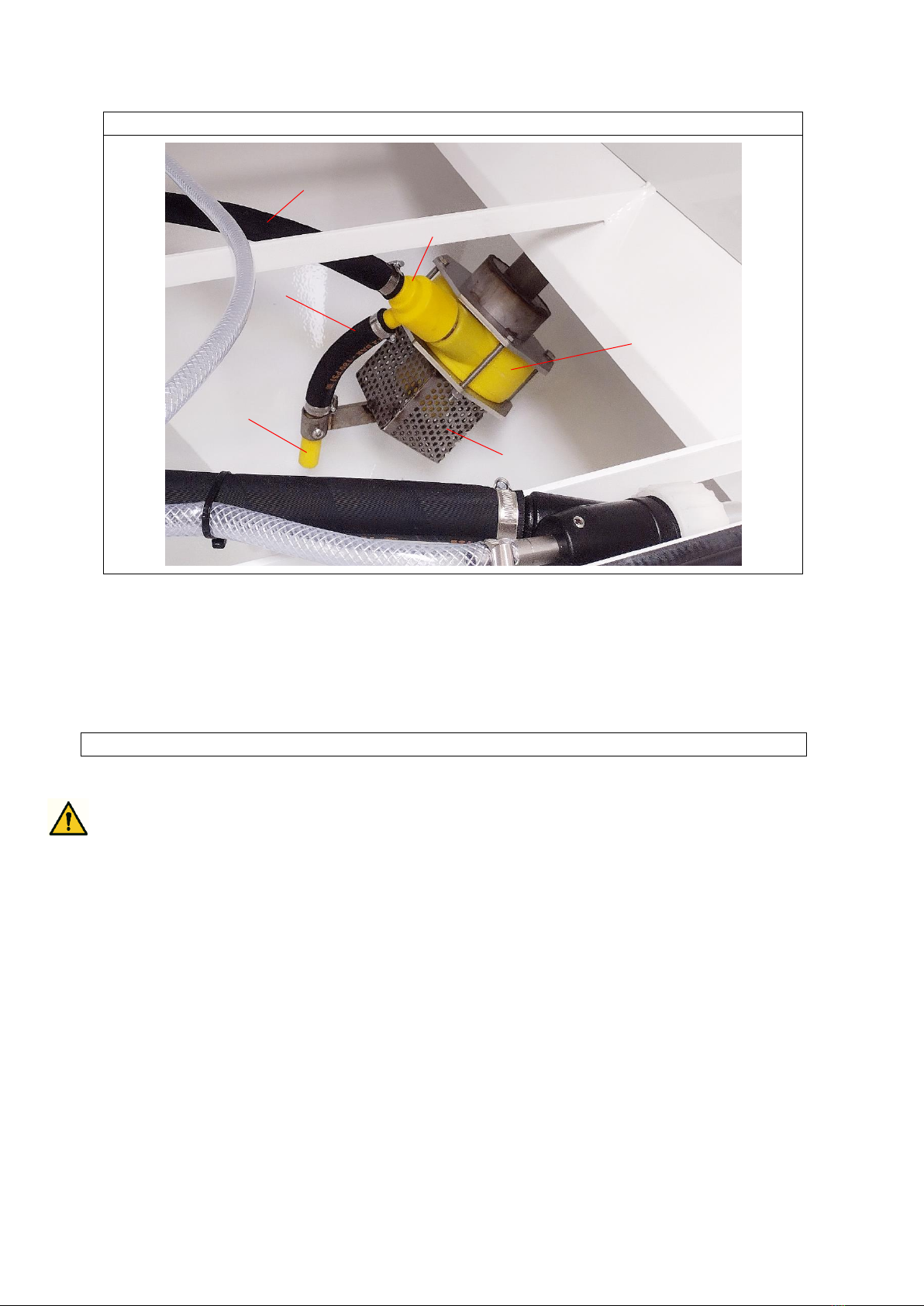
PUMP HOUSING/POLY T PIECE/AGITATION NOZZLE
10. OPERATING INSTRUCTIONS
WARNING: The machine should be installed and used in ventilated area, free of flammable liquids or
gases.
To clean a part:
1. Open the door
2. Place parts onto the work bed (maximum weight 250kg)
3. Close the door (this has a slam shut handle so will need some force to close)
4. Press the reset button on the front control panel (on the right leg)
5. Open screen wash valve (so there is a slow trickle of water down the screen)
6. Hold the blast gun firmly in your hand and depress the foot switch to start the
blasting process.
7. Aim the gun at the part holding approx. 6 - 10 inches from the component to be
cleaned.
8. Once the component is cleaned to the desired finish release the foot switch and turn
the screen wash valve off.
BLAST HOSE
POLY T PIECE
AGGITATION HOSE
AGGITATION NOZZLE
PUMP GUARD
PUMP BODY

P a g e 20 | 24
9. Using the rinse off gun give the component a good rinse down until all media
contamination is removed.
10. Use the external air gun to blow the component dry.
11. Open door and remove component.
CAUTION: To prevent a slip hazard, always make sure a cleaned part is dry and drip-free before
unloading it
11. MAINTENANCE OF MACHINE
In order to avoid the accumulation of dirt in the internal side of the gloves over time, wear
additional single-use gloves (liners) before introducing your hands in the integrated gloves.
WARNING: No user serviceable parts—do not intervene on, tamper on, repair or modify the
machine in any way. Use only degreasing agents recommended or approved by the company.
Maintenance and repair interventions on the machine are to be performed only by the
manufacturer’s authorized service representative. Service representatives of the machine must have
all the knowledge needed for operating the machine and must disconnect power before working on
the machine.
In case of repair or maintenance needs, contact the manufacturer or an authorized representative of
the manufacturer. This includes, but is not limited to, the need to maintain or change the drum and
its content. Service operators of the machine must have all the knowledge needed for operating the
machine.
NOTE: To ensure proper functioning of the machine, rinse the inside of the machine down every day
and clean all media that has collected in the drip tray. Check that there are no blockages in the
return pipe from the drip tray.
It is recommended to check the water level in the closed loop tank weekly as this may need topping
up with water.
Use of the machine will cause the water/detergent to accumulate oil, grease, dirt, and other
contaminates. This will require regular changing of the filter paper on the closed loop tank and
removing any visible solids from the filter tray, this will help to separate oil/grease and spent media
from water solution and thus extend its usage life.
WARNING: Waste generated by maintenance, service and operation of the device is necessary to
liquidate according to the local legislation.
USE ONLY STORM GUARD AQUEOUS CLEANING SOLUTION AND MANUFACTURER APPROVED
MEDIA.
This manual suits for next models
1
Table of contents


