AVDesignHaus Dereneville DAE-01 CL User manual

User manual
Drive unit DAE-01 CL
DAE-01 CL
Dereneville High End - a decision for a lifetime.

User manual Drive unit DAE-01 CL
2
Dear customer,
We congratulate you on your purchase of this new and worldwide unique
drive unit for analog turntables, whose extensive possibilities we would like
to explain to you in the following.
In this drive unit we have combined the advantages and precision of digital
technology with the pure, analogue part of music.
Our motivation: Thinking the feasible and doing the thinkable.
Our principles: We only believe in physical limits and the technically
feasible.
Our maxim: No compromises!
During the six years of development, we repeatedly encountered obst-
acles and seemingly insurmountable limits. But such setbacks only drove
us further. And, with sometimes massive technical eort, we nally over-
come all obstacles!
Our hardware and software design combines highest precision, exibility
and intuitive operation.
Essential components of our design are:
• Powerful 16-bit microcontroller by Fujitsu
• High-precision embedded real-time operating system
• Software designed, programmed and tested according to automotive
standards
• Sophisticated interrupt system (ensures the „synchronization“ of the
software)
• Papst BLDC-Motor
Now we are particularly proud to be able to oer to you the result of our
eorts. If, despite our careful quality control, you should ever have reason
for complaint or a question about the device, please do not hesitate to con-
tact us directly.
Dereneville by AVDesignHaus
Rothertstrasse 8 · 59555 Lippstadt · Germany
Tel.: +49 (0) 2941 66 91 118
www.dereneville.de
www.avdesignhaus.de
eMail: [email protected]
© 2020 Dereneville by AVDesignHaus
Changes, errors and mistakes reserved. The removal of the copyright
notice and the use of content, even in part, violates applicable law and is
expressly prohibited.

User manual Drive unit DAE-01 CL
3
Table of contents
1. Explanation of symbols, environmental protection 4
1.1 Explanation of symbols 4
1.2 Important information 4
1.3 Environmental protection 4
2. Safety instructions 5
3. General information 6
3.1 Operating statuses 6
3.2 „On“ 6
3.2.1 The motor runs 6
3.2.2 The motor is stopped 6
3.2.3 The motor is stopped and there are alerts 6
3.3 „O“ 7
3.4 Motion Care function 7
4. Operation 8
4.1 The control panel 8
4.2 Switch on the drive unit („On“) 8
4.3 Switch o the drive unit („O“) 8
4.4 Activating Motion Care function 8
4.5 Starting/stopping the motor 8
4.6 Select speed 8
4.7 Vary standard speed („Pitch“) 9
4.8 Operating time alerts 9
5. Congurationmenu 10
5.1 Call up Conguration menu 10
5.2 Channel selection 10
5.3 Changing channel value 10
5.4 General conguration channels 11
5.4.1 Dimmer 11
5.4.2 Key Delay 11
5.5 Overview set channels 12
5.5.1 Speed adjustment 12
5.5.2 Drive dynamics 12
5.5.3 Gain 12
5.5.4 Brake, Acceleration 12
5.5.5 Max. Operating time until alerts 13
5.5.6 Display of operating duration of motor and
drive unit 13
5.5.7 Reset 13
6. Disposal instructions 14
7. Warranty 14
8. General terms and conditions 14
9. Dimensions DAE-01 CL 15

User manual Drive unit DAE-01 CL
4
1. Explanation of symbols, environmental protection
1.1 Explanation of symbols
Warning notes
Warning notes in the text are marked by a war-
ning triangle.
In addition, signal words indicate the type and
severity of the consequences if the measures to
avert the danger are not followed.
The following signal words can be used in this document:
NOTE means that damage to property may occur.
WARNING means that serious to life-threatening personal injuries
can occur.
DANGER means that serious to life-threatening personal injury will
occur.
Important information without dangers for people or things
are marked by the adjacent symbol. These informations are
limited by lines above and below the text.
1.2 Important information
Symbol Meaning
►Instruction for action
➔Reference to a text passage in the document
Enumeration/List entry
- Enumeration/List entry
(2nd level)
1.3 Environmental protection
Packaging disposal
The packaging protects the device from transport damage. The packaging
materials have been selected according to environmentally friendly and
disposal aspects and can therefore be recycled.
The return of remaining packaging parts, such as packaging tapes, PE
bags etc., into the material cycle saves raw materials and reduces the
amount of waste.
Your dealer will generally take back these packaging parts.
If you dispose of the packaging parts by yourself, please ask for the
address of the nearest reusable material and recycling centre!

User manual Drive unit DAE-01 CL
5
WARNING!
NEVER operate the unit with a mains voltage
other than the recommended 110-240V.
This could cause a fire or destroy the unit!
NOTE:
Avoid operating or installing the device in env-
ironments with temperatures below -10°C
(+14°F) or above +40°C (+104°F).
Avoid direct sunlight on the device and operation
in excessively dusty environments.
WARNING:
This appliance can be operated by children over 8
years of age and by persons with physical, mental
or sensory disabilities or persons without expe-
rience and knowledge, provided that they have
been supervised beforehand or have received
instructions for the safe operation of the applian-
ce and have understood any danger.
Children must not play with the appliance.
WARNING!
NEVER operate the appliance if there is obvious
damage to the mains plug, the mains cable, the
mains adapter or the appliance itself!
WARNING!
Repairs only by the manufacturer.
2. Safety Instructions
Read these operating instructions carefully and completely before
attempting to install and operate the device!
Keep these operating instructions in a safe place.
This manual contains important safety and operating instructions for
the use of the drive unit.
If the device is sold hand over this document to the buyer.
DAE-01 CL
This device is supplied with operating voltage by a high-quality plug-in
power supply unit. Optionally the length-regulated transformer power
supply DPS-24 VDC is available.
The device contains no user-serviceable parts.
Follow the instructions and notes to avoid damage to the device!
Follow the instructions of a warning to avoid serious injury!
Please use this drive unit only according to the instructions in this
operating manual.
The device is designed exclusively for closed rooms operation.
The unit may only be opened or serviced by a qualified technician.

User manual Drive unit DAE-01 CL
6
3. General information
The drive unit is based on a powerful BLDC motor (brushless DC motor),
which is controlled by a powerful Fujitsu 16 bit microcontroller (auto-
motive standard). This enables functions that underline the outstanding
position of this drive unit:
• Quartz precision speed control.
• Individual adjustability of all speeds with extrem high precision.
• Flexible, variable drive dynamics to accommodate different
belt/platter pairings.
• Pitching (almost) without limits.
• The Motion Care function with individual settings automatically
maintains drive belt and bearings.
• Recording operating time for drive belt and pickup.
The following parameters can be stored:
Speed 33,33
45,00
Drive dynamics Max. Acceleration
Max. Brake
Gain
Recording operating time Drive Belt
Pickup
3.1 Operating statuses
The drive unit is always in one of the following operating statuses:
• ON:
The drive unit is ready for use.
• OFF:
The drive unit is in standby mode and is awaiting its next use.
• MotionCarefunction:
The drive unit „wakes up“ after a waiting period and turns the turn-
table only for about 20 s to maintain the drive belt and bearings at a
lowered speed.
3.2 „ON“
3.2.1 The motor runs
When the motor runs, the corresponding speed of the platter is displayed.
If a speed deviating from the standard value has been selected („Pitch“),
the display shows the actual speed.
If the motor accelerates or brakes,
the target speed display flashes to indicate
that the target speed has not yet been achieved.
The characteristics of this dynamic can be configured, which means that
the duration of this process varies depending on the setting (➔ 5.5.2).
3.2.2 The motor is stopped
Display when the motor is stopped:
3.2.3 The motor is stopped and there are alerts
The drive unit records the operating time of the components „drive belt“
and „pickup“. A maximum operating time can be set for each of these
components. If one or more of the components reaches the maximum
operating time, a alert message appears on the display.
If the adjustable limits for the max. operating time of the drive belt or
one or more pickups are reached, the corresponding alerts are displayed,
alternating with the display for the currently active pickup, indicating that
the selected maximum operating time of a component has been achieved.
Max. operating time drive belt achieved
Max. operating time pickup achieved
Max. operating time drive belt and pickup achieved
NOTE:
These warnings are only notes on possibly worn com-
ponents.
They do not affect the functionality of the drive unit in
any way however!

User manual Drive unit DAE-01 CL
7
3.3 „OFF“
The drive unit is switched off and is in standby mode. The motor is in free-
wheel mode and can be moved easily.
„OFF“ appears in the display and disappears after approx. 10 s.
after 10 s
3.4 Motion Care function
The Motion Care function maintains the drive belt and all bearings asso-
ciated with the platter movement. To do this, the drive unit „wakes up“
after a waiting time of 24 h and rotates the platter at a reduced speed for
about 20 s.
Once the set rotation time has elapsed, the motor stops and the drive unit
starts to countdown the waiting time until the next run of Motion Care.
When the Motion Care function is activated, the current status of the func-
tion is shown on the display.
Display MotionCareStatus
The remaining time until the next Motion Care run is
displayed in „hh.mm“.
If the remaining time until the next Motion Care run is
less than 1 h, the display changes to „mm.ss“.
The leading „P“ indicates an active „Motion Care“ run.
While a Motion Care run is performed, the remaining
active time is displayed in seconds „ss“.

User manual Drive unit DAE-01 CL
8
4. Operation
4.1 The control panel
On Off
33
45
Display
4.2 Switch on the drive unit („On“)
► By pressing the [On Off] key for approx. 3 s, the drive unit changes
from standby mode „Off“ to operating mode „On“.
Modus ►Display
Operating mode
„On“
for approx. 3 s
► By pressing the [On Off] key for approx. 6 s, the drive unit changes
from activated motion care function to operating mode „On“.
Modus ►Display
Operating mode
„On“
for approx. 6 s
4.3 Switch off the drive unit („Off)“
► By pressing the [On Off] key for approx. 3 s, the drive unit changes
from operating mode „On“ respectively from activated Motion Care
function to the standby mode „Off“.
Modus ►Display
„O“
standby mode
more than 3 s
after 10 s
4.4 ActivatingMotionCarefunction
► By pressing the [On Off] key for more than 6 s, the drive unit changes
from operating mode „On“ respectively from the standby mode „Off“
to activated Motion Care function.
Modus ►Display
MotionCare
function
more than 6 s
4.5 Starting/stopping the motor
► To start the motor, press key [33 45] to select the last used platter
speed.
As long the motor accelerates or brakes, the target speed display flashes,
to indicate that the target speed has not been reached yet.
As soon as the drive unit reached the target speed, the speed is displayed
continuously.
► Press [On Off] to stop the motor.
The drive unit changes to operating mode; the display shows „0“ (➔ 4.2).
4.6 Select speed
The drive unit provides 2 speeds.
The selection is made by pressing key [33 45].
Key [33 45] switches 2 speeds: For the first time it is pressed a speed of
33.33 rpm is set.
Pressing key [33 45] again sets the speed to 45.00 rpm. Each further actua-
tion of key [33 45] switches between the speeds 45,00 rpm and 33.33 rpm.

User manual Drive unit DAE-01 CL
9
4.7 Vary standard speed („Pitch“)
Each of the standard speeds can be varied with a resolution of 0.01 rpm.
There are no restrictions regarding the setting value: The speed can be set
from the minimum to the maximum possible speed of the motor.
► Press keys [33 45] (repeatedly) to select the desired speed of the
platter.
The motor starts and accelerates to nominal speed.
► Press [+] to increase speed.
► Press [-] to decrease speed.
Short pressing changes the speed by 0.01 rpm. Longer pressing changes
the speed continuously, whereby the step size of the speed change
increases by the duration of the key operation.
The maximum step size of the change can be set individually in the confi-
guration menu under menu item „Key Delay“.
The display shows the target speed. As long as the display is flashing, the
drive unit is in the dynamic phase and the selected speed has not yet been
achieved.
A pitch setting will not be stored!
A varied speed setting is retained only until key [33 45] is
pressed again or the device is switched off with key [On Off].
4.8 Operating time alerts
In order to ensure optimum playback quality and to protect your valuable
vinyl discs, the drive belt and pickup should be replaced after a certain
period of operation.
We have therefore integrated separate hour meters for drive belt and
pickup into these drive units.
The number of hours until a operating time alert for component replace-
ment appears on the display can be set individually in the Configuration
menu (➔ 5.5).
When the maximum operating time of the drive belt and/or the pickup has
been reached, the corresponding warning notes are shown, alternating
with the display of „0“, indicating that the adjusted maximum operating
time of a component has been achieved.
Max. operating time drive belt achieved
Max. operating time pickup achieved
Max. operating time drive belt and pickup achieved

User manual Drive unit DAE-01 CL
10
5. Configuration menu
The Configuration menu allows the individually adaptation of the drive
unit to the requirements of the platter.
For the correct speed, the relationship between the pulley and the platter
must be considered very carefully. It is also very important to optimize
acceleration and braking forces in order to match the material properties
of the drive belt and the mass of the platter.
This allows the drive unit to be optimally adjusted to the pairing with the
platter and adapted to actual conditions.
The channels are not numbered consecutively, they are organized in mea-
ningful categories:
• Channels below 100 are intended for the general channels „Dimmer“,
„Key Delay“ and „Pickup“.
• Channels 100 ... 123 concern the „Set“
• Channel 999 is for reset to factory defaults
„Gaps“ in channel numbering during selection therefore are completely
normal.
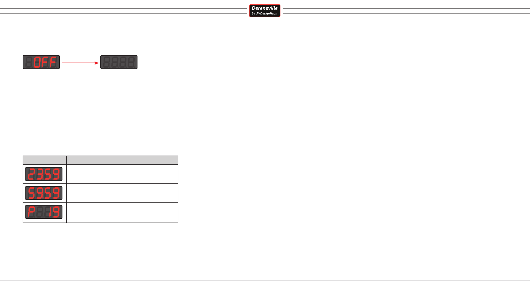
5.1 Call up Configuration menu
► Press and hold the [On Off] key and then briefly press the [-] key to
enter the Configuration menu.
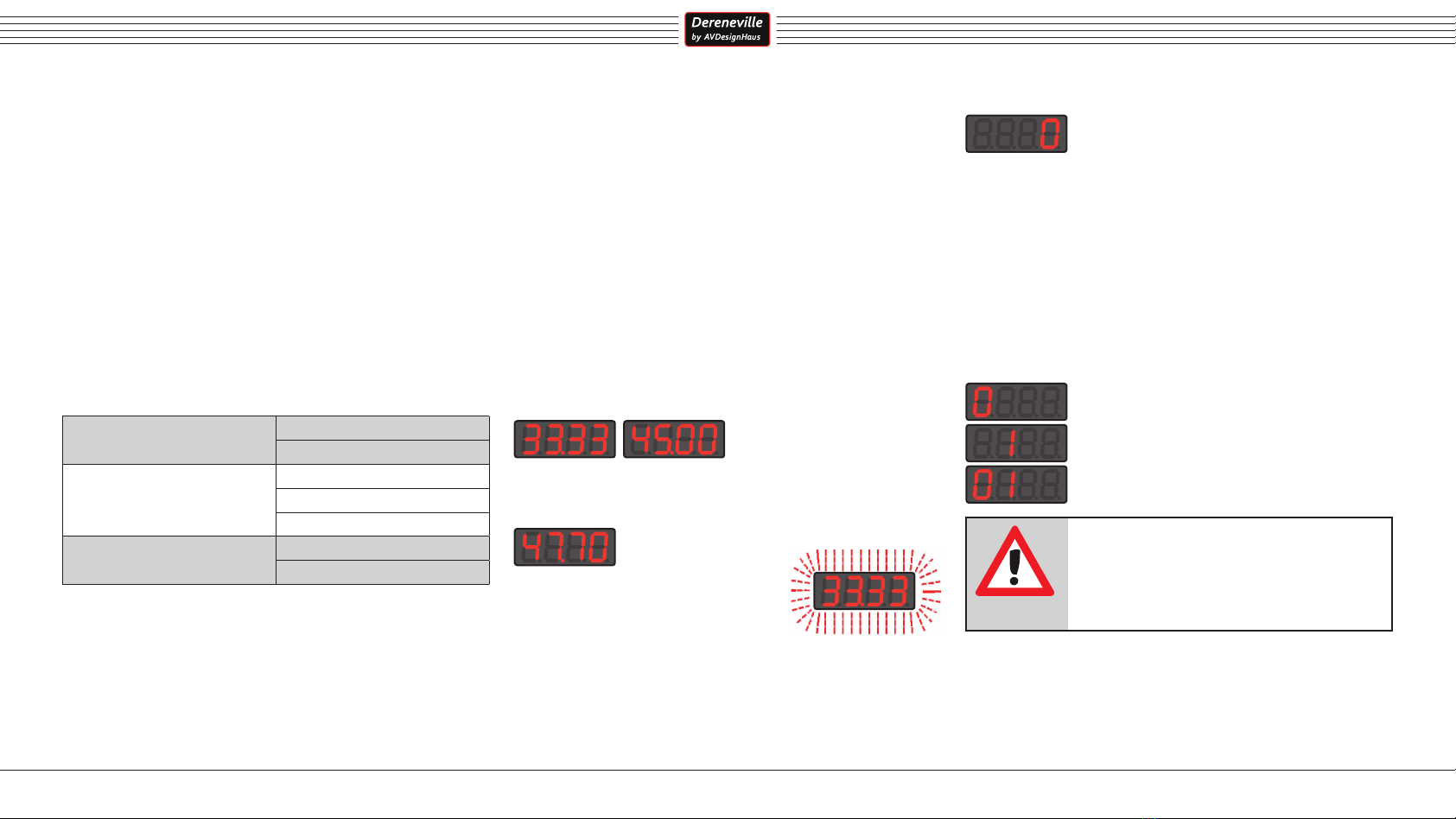
The display changes to the channel display („c“ and channel number):
Function ►Display
Congurationmenu
+
► Press [On Off] to exit the Configuration menu.
5.2 Channel selection
► Press [+] to increase channel number.
► Press [-] to decrease channel number.
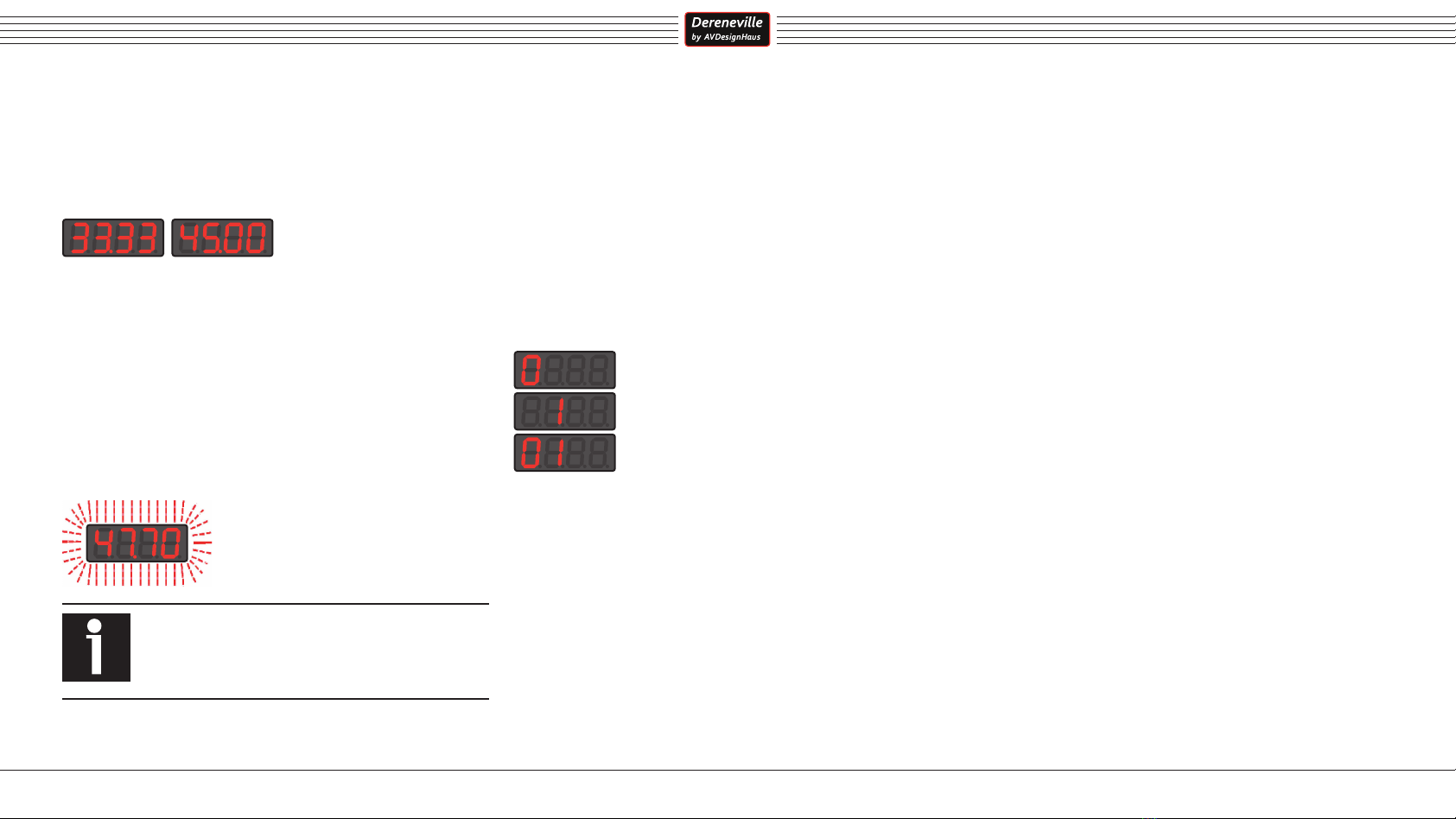
After selecting the channel to be edited, the channel number and the cur-
rent value for this channel are displayed alternately.
channel valuechannel number
5.3 Changing channel value
► Press and hold the [33 45] key and then briefly press the [+] key to
increase channel value.
► Press and hold the [33 45] key and then briefly press the [-] key to
decrease channel value.
Pressing and holding the buttons [+] / [-] for a longer time will change the
channel value continuously, whereby the step size of the change of the
channel value increases by the duration of the button operation.
► Press and hold the [33 45] and [On Off] key to restore the original
channel value („Undo“).
While the channel value is changed, only the channel value is shown in the
display.
The effect of change a channel value is immediate, if possible. For exam-
ple, the speed settings are directly passed on to the motor with each chan-
nel value change, so that the resulting changes can be checked directly.
If the value of a channel is not changed for a certain time, the current value
for this channel and the channel number is displayed alternately again.
When you exit the Configuration menu by pressing the [On Off] key,
changed channel values are stored in the non-volatile memory and thus
remain safely stored until any later changes are made, even in the event
of a power failure.
Some channels are used only to display actual values.
A change of these channel values therefore is not possible.
There is no need to hurry while changing values in the Con-
figuration menu.
The Configuration menu will not be exited until the [On Off]
key has been pressed.

User manual Drive unit DAE-01 CL
11
5.4 General configuration channels
Channels below 100 are intended for the general channels „Dimmer“, „Key
Delay“, „Set“ and „Pickup“.
5.4.1 Dimmer
These channels control the brightness behavior of the display.
During the operation the display is dimmed brighter (Dimm Max) to facili-
tate the operation of the drive unit.
If no more operation is made, the display remains bright for some time
(Dimm Delay) and then darkens (Dimm Min) in order not to be disturbingly
noticed.
Channel Function Variable Range of values
1Dimm Min yes 0,0 - 99,0
2Dimm Max yes 0,0 - 99,0
3Dimm Delay yes 00,01 - 02,00
5.4.2 Key Delay
Values can be changed step by step by short keystrokes or continuously
by longer keystrokes.
Prolonged pressing changes a value continuously, whereby the step size
of the change of the value increases by the duration of the key operation.
This channel controls the speed at which the step size increases when a key
is held down permanently.
The larger the value of this channel, the slower, the smaller the value of this
channel, the faster the step size increases.
Channel Function Variable Range of values*
10 Key Delay yes 10 - 200
*Factory setting: 25
5.5 Overview set channels
Channel Function Variable Range of
values
100 33,33 rpm coarse setting yes 19 - 166
101 33,33 rpm ne setting yes 0 - 999
102 45,00 rpm ne setting yes 0 - 999
110 Gain yes 1 - 200
111 Acceleration yes 10 - 999
112 Brake yes 10 - 999
120 Timer Drive belt target yes 0 - 9999
121 Timer Drive belt actual no Time
122 Timer Pickup target yes 0 - 9999
123 Timer Pickup actual no Time
We recommend the following standard settings:
Gain (Channel 110) = value: 150
Acceleration (Channel 111) = value: 400
Brake (Channel 112) = value: 100
With these settings the time for acceleration is approx. 5 s and the time for
deceleration also approx. 5 s.
5.5.1 Speed adjustment
The speed adjustment should be done very carefully, because of its enor-
mous importance.
► Setting the speed 33.33 rpm coarse. We recommend the use of a 300
Hz stroboscope disc and a 300 Hz stroboscope to perform this setting.
Channel Function Variable Range of
values
100 33,33 rpm coarse setting yes 19 - 166
NOTE
If the speed 33.33 rpm cannot be set correctly within
the value range, the existing pulley must be exchanged
for a suitable one.
From the setting of the 33.33 rpm coarse value the speed 45.00 rpm is
derived.
► After the speed 33.33 rpm is adjusted coarse, the fine setting follows.
Channel Function Variable Range of
values
101 33,33 rpm ne setting yes 0 - 999
When the platter is spinning at the desired speed:
► Return to „33.33 rpm coarse setting“ (Channel 100).
► There, change the current value once and then restore the original
value (e.g. from value 60 to 61 and back to 60 again).
Through this measure, the „33.33 rpm fine setting“ is also taken into
account into calculation of speed 45.00 rpm.
► Although both speeds are already set very precisely now, we re-
commend you to check each individual speed again and adjust it
slightly if necessary.
Channel Function Variable Range of
values
102 45,00 rpm ne setting yes 0 - 999
The fine settingsof speed 45.00 rpm has no influence on speed 33.33 rpm.

User manual Drive unit DAE-01 CL
12
5.5.2 Drive dynamics
The drive unit is equipped with a very powerful motor, which easily accele-
rates or decelerates even a 60 kg-platter to its nominal speed.
The power transmission between the drive unit and platter is of particular
importance in this context.
By changing the drive dynamics of the drive unit (acceleration and dece-
leration behavior), specific properties of the components involved in the
power transmission can be taken into account:
• Drive Belt
Design, elasticity, surface and friction coefficients (material used)
• Platter
Weight, surface and friction coefficients (material used)
• Pulley
Diameter, surface and friction coefficients (material used)
Thus a heavy platter can be accelerated or decelerated comparatively
gently, whereas a light platter can be accelerated or decelerated very fast
to nominal speed.
The values for „Brake“ and „Acceleration“ are parameters for linear func-
tions, while „Gain“ is a first-order nonlinear function. Linear and nonlinear
functions together form the drive characteristic.
Channel Function Variable Range of
values
110 Gain yes 1 - 200
111 Acceleration yes 10 - 999
112 Brake yes 10 - 999
We differentiate between „Brake“ and „Acceleration“, although the com-
ponents involved will behave the same in both situations.
This, however, allows the user, for instance for aesthetic reasons, to acce-
lerate the platter differently from deceleration.
5.5.3 Gain
„Gain“ describes the non-linear behaviour of 1st order during acceleration
or deceleration. The set value describes the gradient of the drive characte-
ristic curve with which the nominal speed is achieved.
Channel Function Variable Range of
values
110 Gain yes 1 - 200
The higher this value is set, the „steeper“ the drive characteristic curve is
and the faster the nominal speed is achieved.
In the above diagram examples of „Acceleration“ are shown in blue and
„Brake“ in red.
5.5.4 Brake, Acceleration
The values for „Brake“ and „Acceleration“ describe the maximum accele-
ration and braking effect respectively.
The higher these values are adjusted, the stronger the acceleration.
Channel Function Variable Range of
values
111 Acceleration yes 10 - 999
112 Brake yes 10 - 999
However, the set value for „Gain“ is decisive for the course of the drive
characteristic curve. The selected acceleration or braking values can only
limit the drive behaviour.
If, for example, the drive characteristic curve is to be steep but the
acceleration only low, „Gain“ is set to a high value, while „Brake“ and
„Acceleration“ are set to low values.
For the course of the drive characteristic curve, the „Brake“ or „Accel-
eration“ curves are compared with the „gain“ curve.
At each time point of the acceleration process, the respective lower value
is evaluated to control the motor.
In the above example, the drive dynamics during the first 3 s is determined
by the linear course of „Acceleration“. After that, „Gain“ provides smaller
values and therefore is taken as the result.
The same applies analogously to the braking process shown in red.

User manual Drive unit DAE-01 CL
13
5.5.5Max.operatingtimeuntilalerts
The max. operating hours are set with the target values. If the actual
values reach or exceed the target values, a alert message appears on the
display (➔ 4.9).
Channel Function Variable Range of
values
120 Timer Drive belt target yes 0 - 9999
121 Timer Drive belt actual no Time
122 Timer Pickup target yes 0 - 9999
123 Timer Pickup actual no Time
5.5.6 Display of operating duration of motor and drive unit
Channel Function Variable Range of values
900 Operating time
(motor only)
no Days
901 Operating time total
(incl. electronics)
no Days
5.5.7 Reset
Channel 999 resets the operating parameters („Set“) to the factory set-
tings. This means
• the speeds are set for a 30 cm platter.
• the operating hour counters for pickup and drive belt and their maxi-
mum operating hours are reseted.
The recorded operating hours for motor and drive unit are not affected
by the reset.
Channel Function ►Display
999 Reset to
factory
settings
+
To perform a reset, please proceed as follows:
► Press and hold the keys [33 45] and [On Off].
The following animation appears on the display:
The reset process can still be aborted by releasing keys [33 45] and [On
Off] during the running animation.
After a few seconds the display will show the following:
The reset has been performed, all parameters have been reset and stored.
► Release keys [33 45] and [On Off].

User manual Drive unit DAE-01 CL
14
6. Disposal instructions
Valid for European Union Countries: According to the European WEEE Di-
rective and its implementation into national laws we take this device back.
For disposal please send the device to the following address:
AVDesignHaus
Rothertstraße 8
59555 Lippstadt
Germany
7. Warranty
Our products are developed and manufactured in Germany according to
the highest quality standards.
Should you have any reason for complaint despite our careful quality cont-
rol, please contact us directly.
AVDesignHaus will do everything in its power to repair the device and res-
tore it to its original condition in a reasonable time.
If this is not possible for technical reasons, AVDesigHaus will replace the
product with a new device.
This limited warranty is valid for a period of two years beginning from the
date of original purchase.
8. General terms and conditions
1. The warranty is limited to the repair of the device. Neither transportati-
on, nor any other costs or risk for removal, transport and installation of the
products is covered by the warranty
2. The warranty is transferable.
3. The warranty is not valid
• for damage caused by incorrect installation, connection or
packaging.
• for damage caused by use, negligence, or use of parts other
than those described in the user manual, or use of parts not
manufactured or authorized by AVDesignHaus.
• for damage caused by defective or inappropriate accessories or
by an unsuitable power supply unit.
• for damage caused by accidents, lightning, water, chemicals,
heat or re, war, public disturbance or other causes.
• beyond the reasonable control of AVDesignHaus and its
authorized partners.
• for devices whose serial number has been changed, deleted,
removed or made illegible.
• for repairs or modications carried out by an unauthorized
person.
4. This warranty supplements all national/regional legal obligations and
does not aect your legal rights as customer..
How to claim repairs under warranty:
If service is required, please contact the dealer from whom the device was
purchased or: www.AVDesignHaus.de
We sincerely wish you a lot of pleasure using your new product!

User manual Drive unit DAE-01 CL
15
9. Dimensions DAE-01 CL
8
14
6
93
87
73,5
100
24 VDC only for Service
H = 10 D = 14
ideale Riemenbreite < = 6 mm
Rundriemen / String < = 2,5 mm
Abmessungen der
Dereneville DAE
-
01 CL
118
Ideal belt width ≤ 6 mm
Round belt Ø ≤ 2,5 mm

Dereneville High End - a decision for a lifetime.
Table of contents