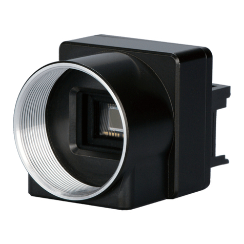
Toshiba teli CSC12M25BMP19 User manual

D4163443A
Ultra-High-Resolution CMOS
Monochrome Camera
CSC12M25BMP19
Operation manual
Contents
BEFORE USE
-
GENERAL SAFETY INSTRUCTIONS.................1
CASES FOR INDEMNITY (LIMITED WARRANTY).....................4
RESTRICTION FOR USE..................................................................4
Usage Precautions ...............................................................................5
1. Outline.............................................................................................8
2. Characteristic...................................................................................8
3. Configuration...................................................................................9
4. Option..............................................................................................9
5. Installation.....................................................................................10
6. Cabling ..........................................................................................11
7. Maintenance port...........................................................................12
8. Specification..................................................................................12
9. Command Communication Protocol.............................................21
10. Register map................................................................................23
11. Function.......................................................................................25
12. External-view Drawing ...............................................................29

D4163443A
1
BEFORE USE
-
GENERAL SAFETY INSTRUCTIONS
This instruction manual contains important information for the operator (user) and/or people in the vicinity to avoid
personal injury, or property damage.
•Prior to use, read this operation manualcarefully to fully understand its instructions forcorrect use.
•After reading, keep this manual near the equipment forfuture reference.
WARNINGS & CAUTIONS
[Definition of markings]
The meaning of each mark used in this instruction manualisgiven below.
Notes *1: Personal injury means wounds, burns, electric shocks, and others for which hospitalization or long
term care are notrequired.
*2: Material damage means any direct or consequential damage related to property or material loss.
WARNING
This mark warns the user that improper use may cause death or severe personal
injuryof the user orpeople inthe vicinity.
CAUTION
This mark warns the user that improper use may cause personal injuries (*1) or
material damages (*2) against the user or people in the vicinity.
This markindicates what the user SHOULD NOTDO. The details are given adjacent the mark.
This markindicates what the user MUSTDO. The details are given adjacent the mark.

D4163443A
2
●Handling Precautions
WARNING
unplug
Immediately cease useof theequipment in the event of abnormality ormalfunction.
If abnormal conditions are present, such as smoke,a burning smell, ingress of water or foreign
matter, or if the equipment is dropped or malfunctions, fire or electric shock may result.
If such abnormalities occur, disconnect the power plug from the outlet and contact your sales
representative.
Do not get wet
Do not use the equipment in locations subject towatersplashes.
Otherwise, fire or electric shock may result.
Never pullapart
Do not disassemble, repair, or modify theequipment.
Otherwise, fire or electric shock may result.
For internalrepair, inspection, orcleaning, contact your salesrepresentative.
Avoid
Do not place anything on the equipment.
If metallic objects, liquid, or other foreign matter enters the equipment, fireor electric shock may
result.
Avoid
Do not install the equipment in an unstable or inclined location or locations subject to
vibration or impact.
Otherwise, the equipment may topple over and cause personal injury.
Do not touch
During an electricalstorm, do nottouch the power cord or connection cable.
Otherwise, an electric shock may result.
Instruction
Use the specified power supply.
Use of an unspecified power supply may result in fire or electric shock.

D4163443A
3
CAUTION
Instruction
Observe thefollowing when installing the equipment:
· Do not cover the equipment with a cloth, etc.
· Do not place the equipmentina narrow location where heatis likely to accumulate.
Otherwise, heat willaccumulate inside the equipment, possibly resulting in a fire.
Avoid
Do not place the equipment in locations subject to high moisture, oil fumes, steam, ordust.
Otherwise, fire or electric shock may result.
Avoid
Do not installthe equipment in locationsexposed todirect sunlight or humidity.
Otherwise, the internal temperature of the equipment willrise, which maycause a fire.
Avoid
Use only specified DC powercables and connection cables.
Otherwise, fire or electric shock may result.
Avoid
When performing connection, turn off power.
When connecting the power cable or connection cable, turn off the equipment power.
Otherwise, fire or electric shock may result.
Instruction
Contactyoursales representative to request periodic inspection and cleaning (every
approx. five years).
Accumulation of dustinside the equipment mayresult in fireor electric shock.
For inspection and cleaning costs, contact your sales representative.

D4163443A
4
CASES FOR INDEMNITY (LIMITED WARRANTY)
We shall be exempted from taking responsibility and held harmless for damage or losses incurred by the user in the following
cases.
In the case damage or losses are caused by fire, earthquake, or other acts of God, acts by a third party, deliberate or
accidental misuse bythe user, oruse under extreme operating conditions.
In the case of indirect, additional, consequential damages (loss of business interests, suspension of business activities) are
incurred as result of malfunction or non-function of the equipment, we shall be exempted from responsibility for such
damages.
In the case damage or losses are caused by failure to observe the information contained in the instructions in this instruction
manual and specifications.
In the case damage or losses are caused byuse contrary to the instructions in this instruction manual and specifications.
In thecase damage or losses are causedby malfunction or other problems resulting from use of equipment or software that
is not specified.
In the case damage or losses are caused by repair or modification conducted by the customer or any unauthorized third
party (such as an unauthorized service representative).
Expenses we bearon this product shall be limited to the individual priceof the product.
RESTRICTION FOR USE
Shouldthe equipment beused in the followingconditions or environments, give consideration to safety measures and inform
usof such usage:
1.Use of the equipment in the conditions orenvironment contrary to those specified, oruse outdoors.
2.Use of the equipment in applications expected to cause potential hazard to people or property, which require special safety
measures to be adopted.
This product can be used under diverse operating conditions. Determination of applicability of equipment or devices
concerned shall be determined after analysis or testing as necessary by the designer of such equipment or devices, or
personnel related to the specifications. Such designer or personnel shall assure the performance and safety of the equipment
ordevices.
This product is not designed or manufactured to be used for control of equipment directly concerned with human life (*1) or
equipment relating to maintenance of public services/functions involving factors of safety (*2). Therefore, the product shall
not be used for such applications.
(*1):Equipment directly concerned with human life refers to:
· Medicalequipment such as life-support systems, equipment for operating theaters.
· Exhaust control equipment for exhaust gases such as toxic fumes or smoke.
· Equipment mandatory to be installed by various laws and regulations such as the FireAct or Building Standard Law.
· Equipmentrelated to the above
(*2) Equipment relating to maintenance of public services/functions involving factors of safety refers to:
· Traffic control systems for air transportation, railways, roads,or marine transportation
· Equipment fornuclear power generation
· Equipmentrelated to the above

D4163443A
5
Usage Precautions
Handle carefully
Do not drop the equipment or allow it to be subject to strong impact or vibration, as such action may cause malfunctions.
Further, do notdamage theconnection cable, since this may cause wire breakage.
Environmental operating conditions
Do not use the product in locations where the ambienttemperatureor humidity exceeds the specifications.
Otherwise, image quality may be degraded or internal components may be adversely affected. In particular, do not use the
product in areas exposed to direct sunlight. Moreover, during shooting under high temperatures, vertical stripes or white
spots (noise) may be produced, depending on the subject or camera conditions (such as increased gain). However, such
phenomena are not malfunctions.
Do not shoot under intense light.
Avoid intense light such as spot lights on part of the screen because it maycause blooming or smears. If intense light falls on
the screen, vertical stripes mayappearon the screen, but this is not a malfunction.
Occurrenceof moiré
If you shoot thinstripe patterns, moiré patterns (interference fringes) may appear. This is not a malfunction.
Occurrenceof noise on the screen
If an intense magnetic or electromagnetic field is generated near the camera or connection cable, noise may be generated on
the screen. If this occurs, move the camera or the cable.
Handling of the protectivecap
If thecamera isnot in use, attach the lens cap to the camera to protect the image pickup surface.
If the equipment is not to be used for a long duration
Turn off power to the camera for safety.
Maintenance
Turn off power to the equipment and wipe it with a dry cloth.
If it becomes severely contaminated, gently wipe the affected areas with a soft cloth dampened with diluted neutral
detergent. Never use alcohol, benzene, thinner, or other chemicals because such chemicals may damage or discolor the paint
and indications.
If the image pickup surface becomes dusty, contaminated, orscratched, consult your sales representative.
Disposal
When disposing of the camera, it may be necessary to disassemble it into separate parts, in accordance with the laws and
regulationsof your country and/or municipality concerning environmental contamination.

D4163443A
6
Following information is only for EU-member states:
The useof the symbolindicates that this product maynot be treated ashousehold
waste. By ensuring this product is disposed of correctly, you will help prevent
potentialnegative consequences for the environment and human health, which
could otherwise be caused by inappropriate waste handling of this product. For more detailed information Approx. the
take-back and recycling of this product,please contact your supplier where you purchased the product.
”This symbol is applicable for EU member statesonly”
[Phenomena specific to CMOS sensor]
■Defectivepixel
Photo sensor elements are arranged in a matrix in a plane for a CMOS image sensor. If any of those photo
sensor elements is defective, the image of the area including the element is not displayed, which generates a
white or black flaw on the monitor screen. The quantity and the brightness of the flaw increase in a higher
temperature condition than the normal temperature condition.
It also increases when the exposure time is longer. The flaw may look like a noise. Note that this is a
characteristic ofa CMOS image sensor and isnot a fault.
■Imageshading
The brightness of the upper part of the screen may be different from that of the lower part. Note that this is a
characteristic of a CMOS image sensor and is not a fault.
This phenomenon isgenerated when the shutter speed is fast.
We recommend that the shutter speed of the camera should be slower than 1/100s to reduce the effect by this
phenomenon.

D4163443A
7
环保使用期限标识,是根据电子信息产品污染控制管理办法以及,电子信息产
品污染控制标识要求(SJ/T11364-2006)、电子信息产品环保使用期限通则,制
定的适用于中国境内销售的电子信息产品的标识。
电子信息产品只要按照安全及使用说明内容,正常使用情况下,从生产月期算
起,在此期限内,产品中含有的有毒有害物质不致发生外泄或突变,不致对环
境造成严重污染或对其人身、财产造成严重损害。
产品正常使用后,要废弃在环保使用年限内或者刚到年限的产品时,请根据国
家标准采取适当的方法进行处置。
另外,此期限不同于质量/功能的保证期限。
The Mark and Information are applicable for People's Republic of China
only.
<
<<
<产
产产
产品中有毒有害物
品中有毒有害物品中有毒有害物
品中有毒有害物质
质质
质或元素的名称及含量
或元素的名称及含量或元素的名称及含量
或元素的名称及含量>
>>
>
有毒有害物质或元素
部件名称 铅(Pb) 汞(Hg) 镉(Cd) 六 价 铬
(Cr(VI))
多 溴 联 苯
(PBB)
多溴二苯醚
(PBDE)
相机本体
× ○ ○ ○ ○ ○
○:表示该有毒有害物质在该部件所有均质材料中的含量均在电子信息产品中有毒有害物质的限量要
求标准规定的限量要求(SJ/T11363-2006)以下
×:表示该有毒有害物质至少在该部件的某一均质材料中的含量超出电子信息产品中有毒有害物质的
限量要求标准规定的限量要求(SJ/T11363-2006)
This information is applicable for People's Republic of China only.
リサイクル
リサイクルリサイクル
リサイクルに
にに
に関
関関
関する
するする
する情報
情報情報
情報(
((
(包装物
包装物包装物
包装物)
))
)
有关再利用的信息
有关再利用的信息有关再利用的信息
有关再利用的信息(
((
(包装物
包装物包装物
包装物)
))
)
Information on recycling of wrapping composition
Information on recycling of wrapping compositionInformation on recycling of wrapping composition
Information on recycling of wrapping composition
段
段段
段ボール
ボールボール
ボール
瓦楞纸板
瓦楞纸板瓦楞纸板
瓦楞纸板
Corrugated cardboard
Corrugated cardboardCorrugated cardboard
Corrugated cardboard
CB
箱
箱箱
箱/
//
/箱子
箱子箱子
箱子/
//
/Box
BoxBox
Box
04
内部緩衝材料
内部緩衝材料内部緩衝材料
内部緩衝材料・
・・
・袋
袋袋
袋
内部
内部内部
内部缓冲材料
缓冲材料缓冲材料
缓冲材料·
··
·袋
袋袋
袋
Internal buffer materials
Internal buffer materialsInternal buffer materials
Internal buffer materials・
・・
・Bag
BagBag
Bag
LDPE
中华人民共和国
环保使用期限
10

D4163443A
8
1. Outline
This CMOS camera is an ultra-precision black-and white camera employing a 12,580 thousand pixel readoutsystem
CMOS sensor.
2. Characteristic
(1) High-speed output of an ultra-high-resolution image
The TOSHIBA TELI’s proprietary 1.9 type 12,580 thousand pixel ultra-precision CMOS sensor outputs the
entire 12,580 thousand pixels in a speed as high as 25fps. A high amount of information in 320M Byte/Sec.
output data rate is obtainable in 8bit mode and 640M Byte/Sec. outputdata rate isobtainable in 10bit mode.
(2) WOI(Window Of Interest)
WOI (Window Of Interest) of a partial readout function optimum to diversifying high-speed image processing
is available.
It supports a variable frame rate to increase the frame rate by reading an arbitrary area by specifying an address
in horizontal and verticaldirections.
(3) Global shutter
As it employs a global electronic shutter similar to a CCD image sensor, clear images of even fast-moving
object are obtainable with less blur.
(4) Random trigger shutter
Photo images can be imported in any timing by inputting external trigger signals.
(5) Camera link interface
Image outputand camera control interfacesemploy the camera linkstandard.
The dual MDR connector supporting Camera Link Medium Configuration outputs the entire 12,580 thousand
pixels in a speed as fast as 25fps. As it also supports Camera Link Base Configuration to output the entire
12,580 thousand pixels in a speed as high as 12.5fps by a single one-sided MDR connector, it can support a
wide variety of image processors.
(6) Wide dynamic range
A wide dynamic range can be achieved by compressing brightness information of an object by employing a
multi-slope multiple storage method (tobe implemented).
(7) Binning
Signalscan beoutput in all effective areas inApprox. 43.5fps by reading 2(H)x2(V) pixels as one pixel.
(8) Sub sampling
The frame rate can be increased byskipping effective pixels.

D4163443A
9
(9) New lens mountTFL-II
TOSHIBATELI’s unique TFL-II mount to take advantage of the resolution of a large high-precision sensor is
employed for the lens mount. The TFL-II mount is large and has a flange back as short as 17.5mm to support
high performance lenses. The lens attaching part is a M48 screw mount with φ50mm positioning engaging
mechanism to support high precision. An F mount lens can also be used via an optional FTAR-2 mount
conversion adaptor.
3. Configuration
(1) Camera ······················································································· 1
(2) Accessories
Instruction manual (Japanese) ······················································· 1
Instruction manual (English)··························································· 1
Application software is not attached to this camera.
4. Option
(1) DC IN cable CPRC3700-**
(2) Camera link cable 14B26-SZLB-***-0LC (Sumitomo 3M)
(Recommended cable length: 5m or less)
(3) Cameraadaptor CA130C
(4) Tripod mounting hardware CPTC12M
(5) F mount conversion adaptor FTAR-2
*NOTE: Contact your dealer / distributor for details of option units.
*Conformity of optionalperipherals and EMC regulations
The adaptability of the safety standard of this camera is guaranteed in the condition of
combination with the above-mentioned option parts. The customer must execute the
confirmation of a final safety conformance with the machine and the entire device when it
combines with parts other than our specification and it is used.

D4163443A
10
5. Installation
This camera has four mounting holes on the bottom and the front each and can be mounted on the equipment with
either face.
Pay attention to the following points to install it.
(1) The length ofa screw inserted intoa camera shall be5mm or less.
(2) Tighten all four screws on the installation surface.
5-1. Example of installation with mounting holes on the bottom
5-2. Example of installation with mounting holes on the front
4-M4
Length of screw available to insert: 5mm
4-M4
Length of screw available to insert: 5mm

D4163443A
11
6. Cabling
The camera link cable and the power cable to connect this camera with the equipment are required. Lock the
connector firmly and fix the cable near the camera to prevent damage on the equipment due to vibration and shock.
Do not bend the cable in smaller radius than the minimum bending radius described below. Otherwise, it may break
the cable. Check with the cable maker for handling the minimum bending radius if other cables than options shown
below areused.
■Option cable
Cable Model Maker
Static minimumbending
radius
(recommended value)
Camera link cable 14B26-SZLB-***-0LC
Sumitomo 3M Ltd. 90mm
Powercable CPRC3700-** TOSHIBATELI
CORPORATION
60mm
“**” indicates cable length.

D4163443A
12
7. Maintenance port
A rubber cap on the back of the camera is attached to protect
the connector for the maintenance of the camera. If the
connector is damaged, the camera may not be maintained. Do
not press the rubber cap firmly. Do not remove the rubber cap
to prevent foreign bodyfromgetting mixed.
8. Specification
[Electric specification]
(1) Imager CMOS image sensor
・Effective number of outputpixels 4096 (H) × 3072 (V)
・Pixelsize 6µm (H) × 6µm (V) Square grid array
・Optical size Equivalent to 1.9 type
(2) Scan mode Progressive
(3) Aspect ratio 4:3
(4) Synchronization system Internal synchronization
(5) Standard object illuminance 2000 lx, F value 5.6, 3000 K
(6) Minimum object illuminance 30 lx
(F2.8,GAIN MAX, readingall pixels, image level 50%)
(7) Imageoutput Compliant to the camera link standard
・Output mode Switchable between Base and Medium configuration
(Factory setting: Medium configuration)
・Data Switch between 8 and 10 bits (Factory setting: 8 bit)
・Reading mode
Reading all pixels Approx. 25 fps / 4096(H) × 3072(V)
Binning Approx. 43.5 fps / 2048(H) × 1536(V)
Sub sampling 2x2:Approx. 50fps / 2048(H) × 1536(V)
4x4:Approx. 100fps / 1024(H) × 768(V)
8x8:Approx. 200 fps / 512(H) × 384(V)
WOI By window setting
Maintenance port

D4163443A
13
(8) Gain
・Digital gain 0 to +18 dB [180 steps] (Factory setting: 0 dB)
(9) Setup 0 toApprox. 13% [528 steps]
(Factory setting:Approx. 3.9%…132 )
(10) Dynamic range Approx. 58 dB (standard)
(11) Gamma 1.0 (standard)
(12) Power voltage DC12 V ±10 % (Ripple 50 mV(p-p) or less)
(13) Power consumption Approx. 5 W
[Electronic shutterspecification]
(1) Shutter speed Shutteroff or 1/20,000 sec to2 sec
The exposure time during shutter off varies depending on the reading mode.
(Factory default: Shutter OFF)
(2) Random trigger shutter ON / OFF switching (Factory default: OFF)
・Fixed mode The exposure time depends on the shutter speed setting.
・Pulse width mode The exposure time depends onthe external triggerpulse width.
Minimumpulse width: 50 µsec (Minimum exposure time: 50 µsec)
[Internalsynchronoussignalspecification]
(1) Scan frequency
・Reading mode *When the shutter is OFF
Reading all pixels Horizontal:Approx. 75 kHz
Vertical:Approx. 25 Hz
Binning Horizontal:Approx. 67 kHz
Vertical:Approx. 43.5 Hz
Sub sampling Horizontal:Approx. 75 kHz
Vertical:Approx. 50 to 200 Hz
WOI By window setting
Note: The brightness of the upper part of the screen may be different from that of the lower part.
Note thatthis is a characteristic of aCMOS image sensor and is not a fault.
This phenomenon isgenerated when the shutter speed is fast.
We recommend that the shutter speed of the camera should be slower than 1/100s to reduce the
effect by this phenomenon.

D4163443A
14
[Inputsignalspecification]
(2) TRIG Camera Link I/F and DC IN connector input
・Signal level (DC IN input) TTLlevel
・Polarity Positive/negative Polarity switchable (Factorydefault: Negative)
・Pulse width 50 µsec or more
[Outputsignalspecification]
None
[Machine dimension]
(1) Lens mount TOSHIBATELI’s unique TFL-II mount
・Mount screw M48mm P=0.75
・Positioning engagement Φ50mm H7
・Flange back 17.5 mm
Request:Combinationallens
Some lenses may not exert full performance of a camera including the decline in the peripheral resolution,
the decline in the reduction of brightness, generation of ghost and aberration. Please check the
combination with this camera forthe lens being used.
Use a TFL-II mount lens whose projecting part from the seating face is 8.1mm or less to be used combined
with this camera.
(2) Dimension 75 mm (W) × 75 mm (H) × 69.5 mm (D)
(Protruding portions such as screws and connectors are not
included.)
(3) Weight Approx. 450g
(4) Camerabodygrounding:insulation status Conductive between circuit GND and camera body
8.1 mm or less
TFL-II-mount lens flange

D4163443A
15
Spectral Sensitivity Specification for CSC12M25BMP19
0.0
10.0
20.0
30.0
40.0
50.0
60.0
70.0
80.0
90.0
100.0
400
420
440
460
480
500
520
540
560
580
600
620
640
660
680
700
720
740
760
780
800
820
840
860
880
900
Wavelength[nm]
Relative Sensitivity [%]
[Usage environment condition]
(1) Performance assurance Temperature: 0 to 40°C
Humidity: 10 to 90% (No dewformation)
(2) Operation assurance Temperature: -5 to 50°C
Humidity: 10 to 0% (No dew formation)
(3) Storage temperature Temperature: -20 to 60°C
Humidity: 90%or less (No dewformation)
[Representative spectral sensitivity characteristic]
(Note that the lenscharacteristic and the light source characteristic are excluded.)
[Various safety standards]
(1) EMC condition (Electro-MagneticCompatibility)
EMI(Electro-Magnetic Interference): EN61000-6-4 / 2001 tobeacquired
EMS (Electro-Magnetic Susceptibility): EN61000-6-2 / 2001 to be acquired
(2) FCC: FCC Part15 Subpart B classAto be acquired
[Communication specification]
(1) Communication speed 9600 / 19200 / 38400 / 57600bps change
(2) Startbit 1bit
(3) Data bit 8bit
(4) Stop bit 1bit
(5) Paritybit None
(6) Handshake None

D4163443A
16
[Connectorpin arrangement]
(1) Image output/control connector (Camera Link Medium Configuration) CAMERA LINK1⋅2
・Connector type: MDR 26-PIN connector 10226-2210PE (3M)
●Connector: CAMERALINK1
Pin No. I/O Signal PinNo. I/O Signal
1 - GND 14 - GND
2 O X0- 15 O X0+
3 O X1- 16 O X1+
4 O X2- 17 O X2+
5 O X CLK OUT- 18 O X CLK OUT+
6 O X3- 19 O X3+
7 I Ser TC(RxD)+ 20 I SerTC(RxD)-
8 O SerTFG(TxD)- 21 O SerTFG(TxD)+
9 I CC1(TRIG)- 22 I CC1(TRIG)+
10 I CC2(MULTI)+ 23 I CC2(MULTI)-
11 I CC3- 24 I CC3+
12 I CC4+ 25 I CC4-
13 - GND 26 - GND
●Connector: CAMERALINK2
Pin No. I/O Signal PinNo. I/O Signal
1 - GND 14 - GND
2 O Y0- 15 O Y0+
3 O Y1- 16 O Y1+
4 O Y2- 17 O Y2+
5 O Y CLK OUT- 18 O Y CLK OUT+
6 O Y3- 19 O Y3+
7 - 100Ωterminated(20) 20 - 100Ωterminated(7)
8 - N.C. 21 - N.C.
9 - N.C. 22 - N.C.
10 - N.C. 23 - N.C.
11 - N.C. 24 - N.C.
12 - N.C. 25 - N.C.
13 - GND 26 - GND

D4163443A
17
(2) Power/synchronous signal input connector DC IN
・Connector (camera side) :HR10A-10R-12PB(71) (HIROSE ELECTRIC)
・Compatible plug (cable side): Equivalent to HR10A-10P-12S(73) (HIROSEELECTRIC) or equivalent
Pin No. I/O Signal
1 - GND
2 I +12V
3 - GND
4 - N.C.
5 - GND
6 - N.C.
7 - N.C.
8 - GND
9 - N.C.
10 - N.C.
11 I TRIG
12 - GND
[Switch setting]
Varioussettings are available with the dip switch on the back.
Memory bank specified Communication speed setting
Switching output mode
O
N
1
2
3
4
5
6
7
8
Unused
“*” indicatesdefault setting at shipment.
(1) Switching output mode
Switch between Medium Configuration and Base Configuration.
The powerof the camera needsbe turned on again toswitch modes.
SW1 Output mode
OFF *MediumConfiguration
ON BaseConfiguration
1
10
2
3
456
7
8
9
11 12
本体背面から見た図
View from the back

D4163443A
18
(2) Communication speed setting
The speed of the serial communication canbe set by thecamera link.
The powerof the camera needsbe turned on again toswitch modes.
SW2 SW3 Communicationspeed
OFF OFF *9600bps
ON OFF 19200bps
OFF ON 38400bps
ON ON 57600bps
(3) Specifying a memory bank before starting
Specifya memory bank to be referenced before turning on the power of the camera for SW4 through SW6.
The powerof the camera needsbe turned on again toswitch modes.
SW4 SW5 SW6 Memory bank
OFF OFF OFF *Bank1
ON OFF OFF Bank2
OFF ON OFF Bank3
ON ON OFF Bank4
OFF OFF ON Bank5
ON OFF ON Bank6
OFF ON ON Bank7
ON ON ON Bank8
Fix SW7 and SW8 to OFF.

D4163443A
19
[Timing chart]
(1) Horizontal timing
*For Mediumconfiguration The figure inparentheses indicates that for Base configuration.

1)Reading all pixels
LVAL
DATA OUT1~4
(DATA OUT1~2) a
f
a = 1048 (2096) CLK b = 4 (8) CLK c = 1024 (2048) CLK
c
d
FVAL
CLK:82.5MHz
b
e
*d = 8 (16) CLK e = 16 (32) CLK f = 1052 (2104) CLK
DVAL
2)CLK rate
●MediumConfiguration
Table of contents
Other Toshiba teli Digital Camera manuals

Toshiba teli
Toshiba teli CSB1100F User manual

Toshiba teli
Toshiba teli BU132M User manual

Toshiba teli
Toshiba teli BU Series User manual

Toshiba teli
Toshiba teli BU Series User manual

Toshiba teli
Toshiba teli BU302M-ES User manual

Toshiba teli
Toshiba teli CSB1100CL-10 User manual

Toshiba teli
Toshiba teli BU406M User manual

Toshiba teli
Toshiba teli DU657MC User manual

Toshiba teli
Toshiba teli DU Series User manual

Toshiba teli
Toshiba teli BC Series User manual