1.DISASSEMBLING PROCEDURE
1. Remove the battery and the SmartMedia.
2. Remove four screws (A110), one screw (A370)
located at the bottom of front panel and one screw
(A430A), and remove the front cover (A100).
3. Remove two flexible cables (H005, W011) con-
nected to the lens part, the flexible cable (W015)
connected to the strobe PC board and two lead
wires (blue or gray (Z002)). (Both leads are sol-
dered.)
4. Disassembling the front cover assembly.
1) Short-circuitthecondenserterminalonthestrobe
PCboardbythecementregister(5W133Ω)and
discharge for 2 ~ 3 sec.
2) Remove three screws (ZL01B) and remove the
lens block (U004).
3) Remove two screws (H004A) and one screw
(H004B). Disconnect the lead wire (W017) of
external strobe terminal and remove the strobe
unit (H004).
4) Remove the microphone (Z002) assembled on
the front cover (A100).
5. Disassembling around the rear cover assembly
1) Removetwo screws(UT01A).Removetheflex-
ible cable (W014), the color LCD lead wire
(H002) and the speaker lead wire (Z001), and
remove the terminal PC board (UT01).
2) Remove the board-to-board connector and re-
move the DC/DC PC board (H001).
3) Remove two screws (A370) (inside the cover of
the SmartMedia) and remove the battery case
(A360).
4) Remove twoscrews(A355) andremove thetop
cover (A300).
5) Removethreescrews(UM01A)andremovethe
microprocessor PC board (UM001).
6) Remove one screw (A420A) and remove the
speaker (Z001).
7) Remove five screws (UD01A). Disconnect the
LCD flexible cable and remove the digital PC
board (UD01).
8) RemovethecolorLCD (H002)fixedwithaboth-
sides adhesive tape.
6. Disassembling the top cover assembly.
1) Remove two screws (A325) and remove the
black & white LCD block (H003).
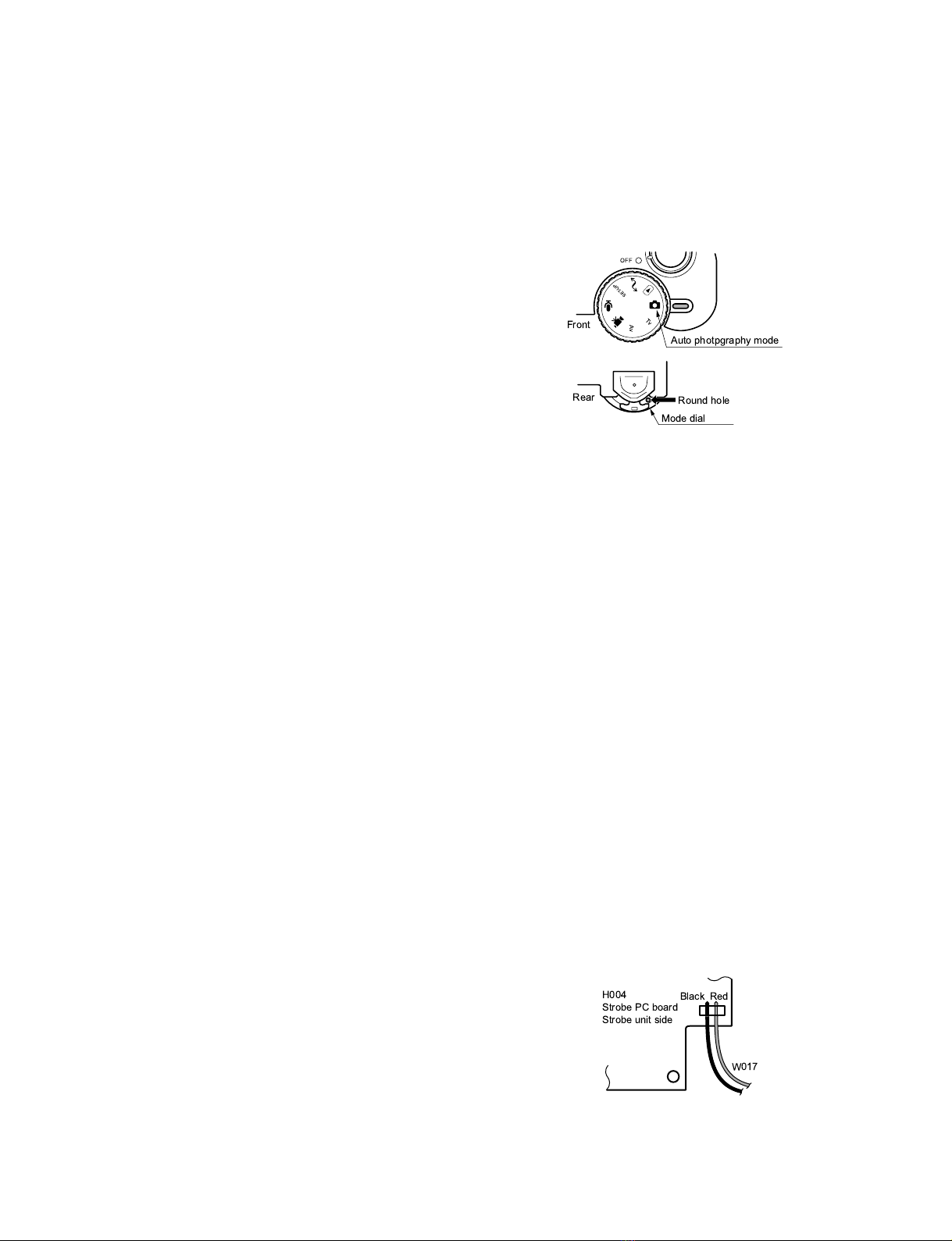
2) Set the mode dial to “Auto photography mode”
asbelow.Pushtheroundholeattherearsideof
the dial with tweezers, etc. (The mode dial plate
is attached with a both-sides adhesive tape.)
Then, remove the mode plate (A340).
3) Remove two screws (A330A) and remove the
mode dial (A330).
4) Remove three screws (US01A) and remove the
switch PC board (US01).
2.NOTES ON ASSEMBLING AND
DISASSEMBLING
·Be sure to discharge the condenser of strobe to
prevent electric shock.
Do not break wires. The wirings using flexible
cables and lead wires are provided inside the
camera.
·When mounting the digital PC board on the rear
cover, be sure to perform it with the cover of the
SmartMedia opened. (Otherwise, the SmartMedia
cover detection switch will be broken. )
·Solder the two lead wires connected between the
PC boards located at front and rear side of the
camera. The blue lead wires are soldered with the
front side and rear side of the camera separated.
·When connecting the speaker and the external
strobe terminal (W017) to each terminal, note the
connectiondirection.Forspeakerterminal,thered
wire is connected to (+) side and the black wire is
to(-)side. For theexternalstrobe terminal, referto
the figure below.
· Mount the speaker without being inclined. Be sure
to make the positioning for the speaker external
groove and the rib of the rear cover.
SET-UP
Tv
Av
OFF
Front
Rear
Auto photpgraphy mode
Round hole
Mode dial
Black
H004
Strobe PC board
Strobe unit side
Red
W017


