manuals.online logo
Brands
  1. Home
  2. •
  3. Brands
  4. •
  5. Toshiba
  6. •
  7. Monitor
  8. •
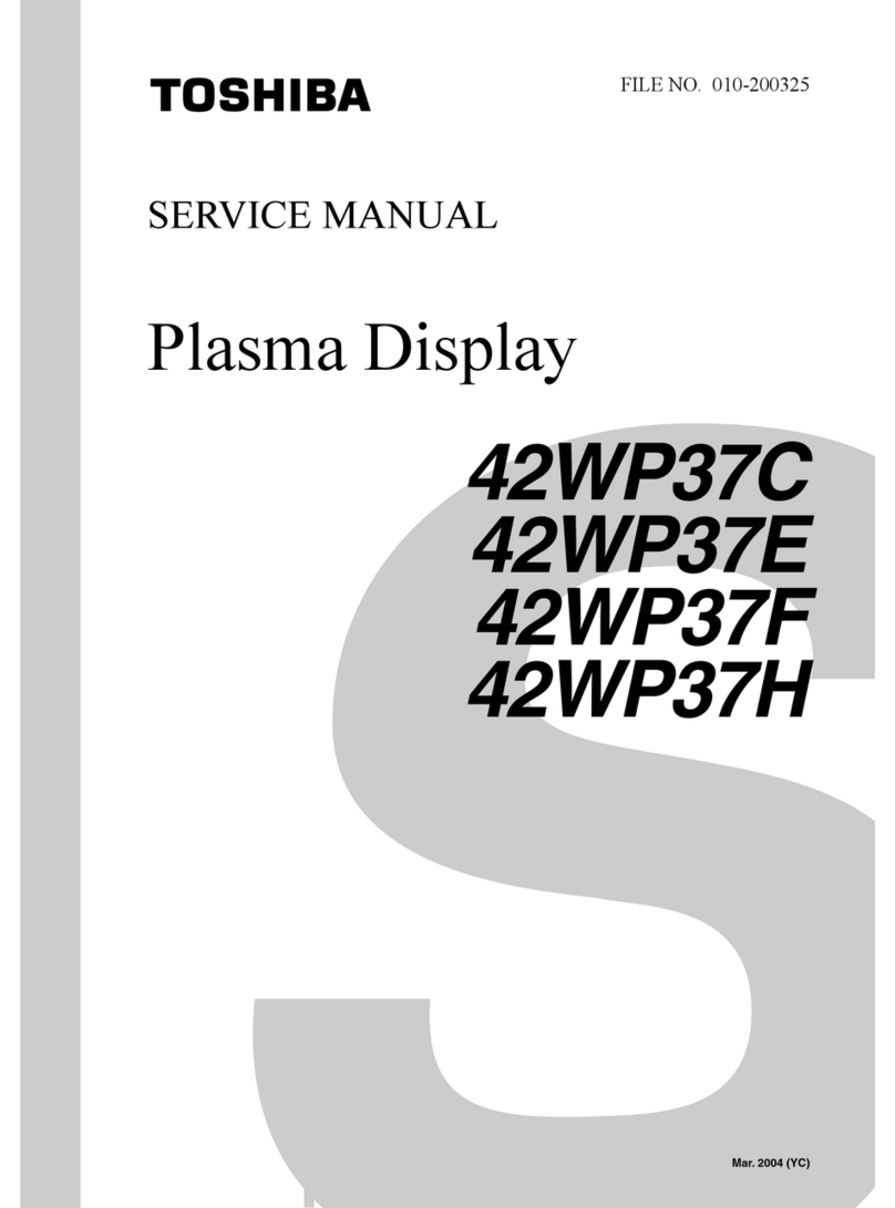
  9. Toshiba 50WP16A User manual

Toshiba 50WP16A User manual

SERVICE MANUAL
PRINTED IN JAPAN Oct.,2001
P
FILE NO. 050-200122
50WP16A, 50WP16C
50WP16H, 50WP16R
50WP16EA, 50HP81
PLASMA DISPLAY MONITOR
Components identified by mark have special characteristics important for safety.
When replacing any of these components, use only manufacture's specified parts.
Important Safety Notice
Notes:
1. Resistor
All resistors are cabon 1/4W resistor, unless marked as follows:
Unit of resistance is OHM [
W
] (K=1,000, M=1,000,000).
: Nonflammable : Metal Oxide
: Solid : Metal Film
: Wire Wound : Fuse:
2. Capacitor
All capacitors are ceramic 50V capacitor, unless marked as follows:
Unit of capacitance is
m
F, unless otherwise noted.
: Temperature Compensation : Electrolytic
: Polyester : Bipolar
: Metalized Polyester : Dipped Tantalum
: Polypropylene : Z-Type
3. Coil
Unit of inductance is
m
F, unless otherwise noted.
4. Test Point : Test Point position
5. Earth Symbol
: Chassis Earth (Cold) : Line Earth (Hot)
6. Voltage Measurement
Voltage is measured by a DC voltmeter.
Conditions of the measurement are the following:
Power Source ................................................... AC 220V-240V, 50/60Hz
Power Source ...................................................
Power
Source
...................................................
(A, B and E Version)
Power Source ...................................................
Power
Source
...................................................
AC 120V, 50/60Hz (U Version)
Receiving Signal ............................................... Colour Bar signal (RF)
All customer's controls ...................................... Maximum positions
7. Number in red circle indicates waveform nember.
(See waveform pattern table.)
8. When arrow mark ( ) is found, connection is easily found from the direction of arrow
9. Indicates the major signal flow. : Video Audio
10. This schematic diagram is the latest at the time of printing and subject to change without
+
-
M
m T
Z
NP
Remarks:
1. The Power Circuit contains a circuit area which uses a separate power supply to isolate the
earth connection.
The circuit is defined by HOT and COLD indications in the schematic diagram. Take the
follwing precautions.
All circuits, except the Power Circuit, are cold.
Precautions
a. Do not touch the hot part or the hot and cold parts at the same time or you may
be shocked.
b. Do not short- circuit the hot and cold circuits or a fuse may blow and parts may
break.
c. Do not connect an instrument, such as an oscilloscope, to the hot and cold
circuits simultaneously or a fuse may blow.
Connect the earth of instruments to the earth connection of the circuit being
measured.
d. Make sure to disconnect the power plug before removing the chassis.
2. Following diodes are interchangeable.
MA150- MA162 (Replacement part)
13 Block and Schematic Diagrams
13.1. Schematic Diagram Notes
71
13.2. Main Block Diagram
P7
P3
P8
P5
P6
To S
C
43
FLOATING
GROUND
from P43
INPUT
-
+
SC
ª¥
¦£«
SC1
SUB-FIELD
PROCESSOR
§£ª¤
§£ª¤ 

¤©¦
§ ¦¥
© §©¦ªª¦©
¦©¤«
¦¥©«©
D33
D
D36 D35
¥«ª
°
«£
° §©¦ªª
¦


¬¦
¤§
DG6
©
ª®
¬¦ ª®
H
P2
SUSTAIN
VOLTAGE
PROTECTOR
SUSTAIN
VOLTAGE
CONTROL
P
OFF
SOS
STB5V
PROCESS
VOLTAGE
PROTECTOR
VSUS
15V
POWER
FACTOR
CONTROL STAND BY

SS8
ª
POWER
SWITCH
§
«¬¥
©
©
¦¤§¦¥¥«
 
ª¦
 © §
¬¦ ¥
©¤¦«
©© §¦®©
£
P1
P5
P7
D5 D7
PROCESS
VOLTAGE
CONTROL
P22
PRIMARY
CIRCUIT
P19
P9
P18
SUSTAIN
VOLTAGE
RECTIFIER
P15
P16
P21
P6
LINE
FILTER
F2

V34
£
SPEAKER
TERMINAL
-
+
©
SPEAKER
TERMINAL
-
+
DG4 DG5
¦¥«©¦£
§¬£ª
½ÉÆÄ 
PROCESS
VOLTAGE
RECTIFIER
ª©
¦¥«©¦£
SC3
SC2
D20
D21
ª¬ª«¥
§¬£ª
¥«£±
§¬£ª
AC100V
- 240V


D32
D34
D31
SS.R. SS.R. SS.R. SS.R.
C1
C13
C11
SS.R. SS.R. SS.R. SS.R.
C3
C33
Vda
SS.R. SS.R. SS.R.
C23
C2
C22
SS.R. SS.R. SS.R. SS.R.

C61
C63


SU




SD














F1
SS.R. SS.R. SS.R. SS.R.

C44
C43
Vda
C41
SS.R. SS.R. SS.R.

C52
C51
SS48
SS1
ADDRESS
VOLTAGE
(VE)
SUSTAIN
PULSE
SS72
SS41
SS16
ªª
Vda
SS15
½ÉÆÄ 
C35
C21
C62
C81
C71
C42
C35
C71
C12
C81
C72
C72
SS27
P27P26
SS12
SS12
+15V
-15V
MUTE
13.5V
5V
3.65V
ª
ª
ª


żÉ
¾Ð
ɼºÆÍ¼É
ª
ª
żÉ
¾Ð
ɼºÆÍ¼É
ª
ª
ª
ª
ª
ª ª
żÉ
¾Ð
ɼºÆÍ¼É
żÉ
¾Ð
©¼ºÆÍ¼É












 

VSUS
VSET
VDA




 

 

 

 

Vda
°
°
©
C53

«
«
À¾À˸à ̽½¼É
T1
P8
VSCN
Vad
F15V
GENERATOR
P41
P43
P4
SC4
§
ª¥
¸»

VSUS
15V
VDA
15V
VDA
72
13.3. Power (F, P1, P3, P4, P5, P6, P7, P8 and P9 Board) Block Diagram
DRIVE VOLTAGE PROTECTOR PROCESS VOLTAGE PROTECTOR
P16
SOS IN
1VCC
P21
10 4367 1
P22
7 4321 6
6FB
8 VSUS VSUS 15V VSET -15Vs 5V
AC IN VBK VDA 15Vs 13.5V
AC INLET IC601 IC602 SOS
P15
P1 To SS1
L4
H6 2 VSUS
3
OSC. 4
IC600
F1 H8
F901 F900 9VDA
L10 10 15V
LINE 13 STOP
P2
To SC1
FILTER 6 15V
1 VSET
2 VSUS
RL401 D402 3
15F9 P9 POWER FACTOR CONTROL 4
3 5 VBK
RL400
P6
To DG6
11 +15V
3 -15V
75V
4 MUTE
P17
To DG17
55V
8 3.65V
9 3.65V
P10-P13 1 13.5V
P19 8 4 5 7 11
P42
31
P41
1To
FAN
3
FAN
P5 To D5
1 13.5V
55V
9 3.65V
8
5 1 P18 11 3.65V
12
P19 9
STB 5V
P7 To D7
7 SOS
P43
6 5 4 2 ON/OFF
4 STB5V
P8 To SS8
1
2MAIN
SWITCH
P26
To C72
2VDA
5 15V
P27
1VDA
5 15V
FULL
WAVE
RECTIFIER
IC400
3
2
1
IC403
AVR
5
1
Q417
Q421
14
11
2
6 4
26
4
D601
Q601 Q635
Q636
D604
D606
IC635
3
8
P3
IC750
COMPARATO
IC751
Q750
Q751
P7
IC775
COMPARATO
Q775
Q776
P8
FULL
WAVE
RECTIFIER
L434
+
Q408
Q409
Q402
T404
Q410
Q414
Q412
Q403
T405
Q411
Q406
Q407
Q413
Q415
2
3
9
10
5
6
12
13
GD
S
D
D
S
GD
L411 D487
IC410
R513 VBK
IC406
R528 VDA75V
IC412
AVR
1 2
15V
D444
IC407
AVR
1 2
5V
Q429
IC411
AVR
1 2
12V
D443
+
13.5V
+15V
-15V
For Audio
D441
D442
+
+
+
IC981
25v 3.65v
P9_1
IC981
25v 3.65v
P9_2
1
2
P29
5
6
P30
1
2
P30
5
6
P29
P5
IC650
OSC.
6
PROTECT
STOP
OCP
Q419
Q400 Q404
GD
Q405
S
L401 D407
D432
Q425
Q401 Q423
GD
Q424
S
L402
Q416
IC735
PFC
7
5
IC737
IC736
Q730
P6
PROTECT
3
4
230V
110V
D439D440
++
D431
Q418
D430
T402
MAIN POWER SWITCH ON/OFF
ON/OFF From MICRO
Q650
Q651
8
STOP
5
3
10
12
11
Q926
Q927
IC934
Vscan
IC932
F15V
Q932
Q933
IC931
Vad
IC921
6
OSC.
T921
DC400V
Start
P4
F
T400
T401
110V_Model
230V_Model
DC400V
4
GDD
G
7
Vcc
73
13.4. P1-Board (1/2) Schematic Diagram
74
13.5. P1-Board (2/2) Schematic Diagram
75
13.6. P3 and P4-Board Schematic Diagram
76
13.7. P5, P6, P7 and P8-Board Schematic Diagram
77
13.8. P9 and F-Board Schematic Diagram
50HP81
50WP16 SERIES
78
VIDEO
IN C
S-VIDEO
IN VIDEO/Y
TO DG BOARD
IC3505 IC3508
COMPONENT/RGB IN RGB - PC SEL. RGB/PC - TUNER SEL.
Pb/B Pb/B Pb/B
Y/G Y/G
Pr/R Pr/R Y/G
B
HD G
VD Pr/R
R
PC IN
B
GDAC2 DAC3 IC3504
RSYNC.SEL.
HD HD
HS
VS
VD
TUNER VD
IN B
GDAC3 SW3 SW2
RIC3507
HD CONTROL
VD
IC3506 DAC2
AUDIO SEL.
AUDIO L0 SCL3
R0 DAC1 SDA3
LDAC0
AV L1 L
R1
RGB/ L2 RR
COMP. R2
L3
PC R3 SCL1
RS232C SDA1
IC3503, IC3511 ~ 14
3
5
6
1
8
16
11
14
9
3
5
6
16
9
1
14
11
8
37
39
Q3517/Q3518
27 12
Q3503
Q3501
2
13
11
12
10
15
1
4
9
5
1
JK3501
11
7
9
3
2
1
14
13
2
1
3
5
4
Q3512
Q3511
Q3510
RGB PC RGB&PC TUNER
Q3513/Q3514
Q3519/Q3514
Q3513/Q3514
Q3521/Q3522
Q3523/Q3524
3
IIC
|
DAC
6
5
49
714
15
10
8
7
Q3527/Q3528
Q3525/Q3526
Q3529/Q3530
12
3
5
2
9
1
15
14
13
4
11
57
56
31
33
REMOTE
INTERFACE
BLOCK 53
52
Q3531/Q3532
DDC
MEMORY
H
2 7 12
10
13.9. H-Board Block Diagram
79
13.10. H-Board (1/4) Schematic Diagram
80
13.11. H-Board (2/4) Schematic Diagram
81
13.12. H-Board (3/4) Schematic Diagram
82
13.13. H-Board (4/4) Schematic Diagram
83
13.14. DG Board Block Diagram
IC8001 IC8014 To
V/Y V/Y IC8018 VPC D-Board
IC8015
Y 7
CSC Y2
1
IC8007 C 0
IC8003 JK8003
PB Y Sub Contrast
C
IC8002 JK8002 7
YTo
D-Board C2
1
IC8004 JK8001 0
PR
IC8008
IC8005 IC8020
RGB SYNC.SEL CLP VS L:3DYC
IC8009 IC8010 L:VPC SCL3
IC8016 & Q8030 IC8033 & Q8033 L:DIGITAL SDA3
IC8011 H:G Sync
HD H:G Sync SYNC.
HD- HP H HD
CLP NCLP CLP
VD VD VP V VD
CLP
AUDIO AMP IC2302 LDG4
LTO SPEAKER
R
IC2301 LDG5
TO SPEAKER
IC2402
MUTE
NTSC
3DYC
COMB
FILTER
83
5
3
16
14
1
84
2 7 12
1
7
6
88
L : 3D YC
SYNC
SEP.
6
4
15
8
13
17
Q8001
31
63
62
COLOUR
DECODER
SYNC.
PROCESS
A/D
COMB
FILTER
38
43
47
46
20
25
29
28
Q8007
/LC8002
1216
37
39
1
5
11
7
9
31
33
Q8006
Q8014
4M DRAM
FIELD MEMORY
13
2
Q8032
Q8031
28
25
43
46
30
33
38
41
31
31
31
Q8005
Q8021
13
SYNC
9
1
8
1
2
10
AV/
RGB/COMP
.
SYNC. SW
6
4
8
IIC
|
SW
5
4
15
7
9
14 13
58
5
DIGITAL
BUFFER
32
1
20
28
6
57
Q2301
11 4
12
12
29
3
21
11 4
12
1
1
Q2302
Q2303
Q2304
DG
11
84
13.15. DG-Board (1/4) Schematic Diagram
85
13.16. DG-Board (2/4) Schematic Diagram
86
13.17. DG-Board (3/4) Schematic Diagram
87
13.18. DG-Board (4/4) Schematic Diagram
88
13.19. T11 Board Schematic Diagram
89

Other manuals for 50WP16A

1

This manual suits for next models

5

Other Toshiba Monitor manuals

Toshiba TheaterWide 23HL84 User manual

Toshiba

Toshiba TheaterWide 23HL84 User manual

Toshiba TD-Z472 User manual

Toshiba

Toshiba TD-Z472 User manual

Toshiba TD-Z422 User manual

Toshiba

Toshiba TD-Z422 User manual

Toshiba TD-P753 User manual

Toshiba

Toshiba TD-P753 User manual

Toshiba P42LHA User manual

Toshiba

Toshiba P42LHA User manual

Toshiba 42WP27B User manual

Toshiba

Toshiba 42WP27B User manual

Toshiba P32LSA User manual

Toshiba

Toshiba P32LSA User manual

Toshiba TechnoRainbow TR 2010E User manual

Toshiba

Toshiba TechnoRainbow TR 2010E User manual

Toshiba 42HP82 User manual

Toshiba

Toshiba 42HP82 User manual

Toshiba 20DL74 User manual

Toshiba

Toshiba 20DL74 User manual

Toshiba TD-P553E User manual

Toshiba

Toshiba TD-P553E User manual

Toshiba 57H84 - 57" Rear Projection TV User manual

Toshiba

Toshiba 57H84 - 57" Rear Projection TV User manual

Toshiba TD-E323 User manual

Toshiba

Toshiba TD-E323 User manual

Toshiba TD-Q553 User manual

Toshiba

Toshiba TD-Q553 User manual

Toshiba CM1320A User manual

Toshiba

Toshiba CM1320A User manual

Toshiba TD-Z551 User manual

Toshiba

Toshiba TD-Z551 User manual

Toshiba PA3923U-1LC3 User manual

Toshiba

Toshiba PA3923U-1LC3 User manual

Toshiba 42HP82 User manual

Toshiba

Toshiba 42HP82 User manual

Toshiba TekBright PA3553 Series User manual

Toshiba

Toshiba TekBright PA3553 Series User manual

Toshiba DIGITAL Series User manual

Toshiba

Toshiba DIGITAL Series User manual

Toshiba TheaterWide 20HL85 User manual

Toshiba

Toshiba TheaterWide 20HL85 User manual

Toshiba 50XP37C User manual

Toshiba

Toshiba 50XP37C User manual

Toshiba TD-Y493M User manual

Toshiba

Toshiba TD-Y493M User manual

Toshiba 26HLC56 User manual

Toshiba

Toshiba 26HLC56 User manual

Popular Monitor manuals by other brands

AG Neovo SX-15 Specifications

AG Neovo

AG Neovo SX-15 Specifications

Lascar EL-WEM quick start guide

Lascar

Lascar EL-WEM quick start guide

Mod-tronic MT300 user manual

Mod-tronic

Mod-tronic MT300 user manual

Samsung ME32C user manual

Samsung

Samsung ME32C user manual

Panasonic TH152UX1 - 152" PLASMA TV Service manual

Panasonic

Panasonic TH152UX1 - 152" PLASMA TV Service manual

Iiyama Pro Lite PLH430 user manual

Iiyama

Iiyama Pro Lite PLH430 user manual

Lenovo D19270QP1 user guide

Lenovo

Lenovo D19270QP1 user guide

Cooler Master GM27-CFX user manual

Cooler Master

Cooler Master GM27-CFX user manual

ViewSonic VA502mb-1 Service manual

ViewSonic

ViewSonic VA502mb-1 Service manual

AOC U2868PQU user manual

AOC

AOC U2868PQU user manual

novotechnik MAP 4000 Series Setup manual

novotechnik

novotechnik MAP 4000 Series Setup manual

Iiyama ProLite X436S user manual

Iiyama

Iiyama ProLite X436S user manual

LG 55MH5K owner's manual

LG

LG 55MH5K owner's manual

Feelworld FW678 HD Operation manual

Feelworld

Feelworld FW678 HD Operation manual

Pioneer PDP-4214HD operating instructions

Pioneer

Pioneer PDP-4214HD operating instructions

Ganz ZM-CR315NP-EU instruction manual

Ganz

Ganz ZM-CR315NP-EU instruction manual

Acer P243W user manual

Acer

Acer P243W user manual

Samsung PL-50P3H Owner's instructions

Samsung

Samsung PL-50P3H Owner's instructions

manuals.online logo
manuals.online logoBrands
  • About & Mission
  • Contact us
  • Privacy Policy
  • Terms and Conditions

Copyright 2025 Manuals.Online. All Rights Reserved.