Toshiba MM20E45 Installation guide
Other Toshiba TV manuals
Toshiba
Toshiba M83 series User manual
Toshiba
Toshiba 43U6763DAT User manual
Toshiba
Toshiba 32D1753DB User manual

Toshiba
Toshiba UA3D63DA User manual
Toshiba
Toshiba CF35E50 User manual

Toshiba
Toshiba 34AS42 User manual

Toshiba
Toshiba 28 Series User manual

Toshiba
Toshiba CN36H90 User manual

Toshiba
Toshiba 46TL868G User manual
Toshiba
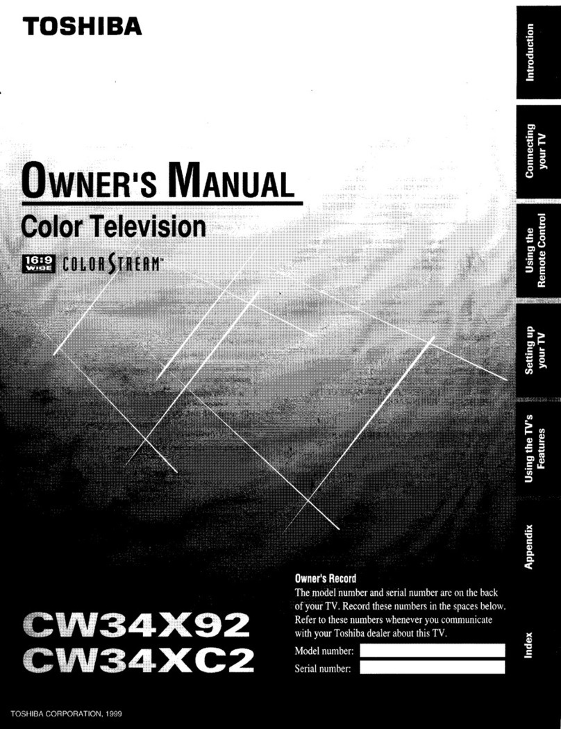
Toshiba CW34X92 User manual
Toshiba
Toshiba TL9 8 Digital Series User manual

Toshiba
Toshiba 32TL515U Assembly instructions

Toshiba
Toshiba 55VL900A User manual
Toshiba
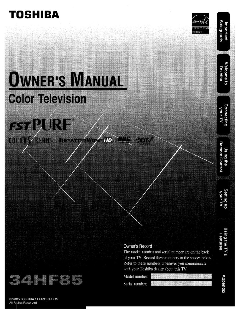
Toshiba 34HF85 - 34" CRT TV User manual

Toshiba
Toshiba 55L7400 User manual
Toshiba
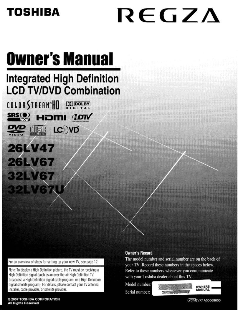
Toshiba REGZA 26LV47 User manual
Toshiba
Toshiba 56MX195 - 56" Rear Projection TV User manual

Toshiba
Toshiba 50L9450 Series User manual
Toshiba
Toshiba CF36G40 User manual
Toshiba
Toshiba 32A15 User manual
