manuals.online logo
Brands
  1. Home
  2. •
  3. Brands
  4. •
  5. Toshiba
  6. •
  7. Water Pump
  8. •
  9. Toshiba TCB-DP32DE User manual

Toshiba TCB-DP32DE User manual

FOR CONCEALED DUCT HIGH STATIC PRESSURETYPE
TYPE DE HAUTE PRESSION STATIQUE À CONDUITS DISSIMULÉS
FÜREINHEITENMITHOHEMSTATISCHENDRUCKIN DER ZWISCHENDECKE
TIPO AD ALTA PRESSIONE STATICA PER UNITA’A CONDOTTO NASCOSTO
MODELO DE ALTA PRESIÓN ESTÁTICA CON CONDUCTOS OCULTOS
TIPO DE CONDUTA EMBUTIDA COM ELEVADA PRESSÃO ESTÁTICA
AFVOERSET VOORHOGE STATISCHEDRUKTYPEMETINGEBOUWDEKANALEN
ΣΥΓΚΑΛΥΜΜΕΝΟΣ ΑΓΩΓΟΣ ΤΥΠΟΥ ΥΨΗΛΗΣ ΣΤΑΤΙΚΗΣ ΠΙΕΣΗΣ
MODEL
TCB-DP32DE
INSTALLATION MANUAL
MANUEL D’INSTALLATION
INSTALLATIONS-HANDBUCH
MANUALE DI INSTALLAZIONE
MANUAL DE INSTALACIÓN
MANUAL DE INSTALAÇÃO
INSTALLA TIEHANDLEIDING
ΕΓΧΕΙΡΙ∆ΙΟ ΕΓΚΑΤΑΣΤΑΣΗΣ
DRAIN PUMP KIT
KIT DE POMPE D’ÉVACUATION
ABSAUGPUMPEN-SET
KIT POMPA DI SCARICO
JUEGO DE BOMBA DE DESAGÜE
KIT DA BOMBA DE DRENAGEM
AFVOERSET
ΚΙΤ ΑΝΤΛΙΑΣ ΑΠΟΣΤΡΑΓΓΙΣΗΣ
+0(H1-H4).p65 2005/02/07, 14:22Page 1 AdobePageMaker6.5J/Win
ブラック
EH99840401
+0(H1-H4).p65 2005/02/07, 14:22Page 2 AdobePageMaker6.5J/Win
ブラック
Thank you very much for purchasing Drain pump kit for TOSHIBA Air Conditioner.
Please read this installation manual carefully before using your Air Conditioner.
· Be sure to obtain the “Installation manual” from constructor (or dealer).
Nous vous remercions d’avoir porté votre choix sur un kit de pompe d’évacuation pour climatiseur
TOSHIBA.
Veuillez lire attentivement ce manuel d’installation avant d’utiliser votre climatiseur.
·Veillez à vous procurer le « Manuel d’installation » chez votre fabriquant (ou revendeur).
Vielen Dank, dass Sie sich für den Kauf des Absaugpumpen-Sets für das TOSHIBA-Klimagerät
entschieden haben.
Lesen Sie diese Anleitung bitte sorgfältig durch, bevor Sie Ihr Klimagerät verwenden.
· Besorgen Sie sich das „Installations-handbuch“ vom Hersteller (oder Händler).
Grazie per avere acquistato il Kit pompa di scarico per Condizionatori d’aria TOSHIBA.
La preghiamo di leggere attentamente questo manuale d’installazione prima di utilizzare il suo
condizionatore d’aria.
· Ricordi di chiedere il “Manuale d’installazione” al costruttore (o rivenditore).
Gracias por adquirir el juego de bomba de desagüe para el aparato de aire acondicionado TOSHIBA.
Lea este manual de instalación atentamente antes de utilizar el aparato de aire acondicionado.
· Asegúrese de obtener el “Manual de instalación” de mano del constructor (o del distribuidor).
Agradecemos a sua compra deste kit da bomba de Drenagem para o Ar Condicionado TOSHIBA.
Leia atentamente este manual de instalação antes de utilizar o seu Ar Condicionado.
· Adquira o “Manual de instalação” através do fabricante (ou representante).
Bedankt om de afvoerset voor de TOSHIBA Airconditioner te kopen.
Lees deze installatiehandleiding eerst helemaal door voordat u de Airconditioner gebruikt.
· De "Installatiehandleiding" kunt u verkrijgen bij uw aannemer (of dealer).
Σας ευχαριστούµε θερµώς για την αγορά του Κιτ αντλίας αποστράγγισης για το κλιµατιστικ
TOSHIBA.
∆ιαβάστε το παρν εγχειρίδιο εγκατάστασης προσεκτικά πριν να χρησιµοποιήσετε το
κλιµατιστικ σας.
·Βεβαιωθείτε τι έχετε το "Εγχειρίδιο εγκατάστασης" απ τον κατασκευαστή (ή τον
προµηθευτή σας).
·
+0(INTRO).p65 2005/02/07, 14:22Page 2 AdobePageMaker6.5J/Win
ブラック
ENGLISHFRANCAISDEUTSCHITALIANOESPAÑOLPORTUGUÊS
NEDERLANDS
ΕΛΛΗΝΙΚΑ
1
Precautions for Safety .............................................................. 1
2
Components............................................................................... 2
3
Installing Drain pump kit .......................................................... 3
4
Installing the Attachment plate............................................... 3
5
Hose Connecting....................................................................... 4
CONTENTS
6
Drain piping ................................................................................ 5
7
Wire Connecting ........................................................................ 5
8
Test Run ...................................................................................... 6
9
Check the Draining.................................................................... 6
1
Précautions de sécurité ............................................................ 7
2
Composants ............................................................................... 8
3
Installation de la pompe d’évacuation................................... 9
4
Installation de la plaque d’attache ......................................... 9
5
Raccordement des tuyaux ..................................................... 10
SOMMAIRE
6
Conduite d’évacuation ........................................................... 11
7
Câblage...................................................................................... 11
8
Essai de fonctionnement ....................................................... 12
9
Vérification de l’évacuation ................................................... 12
1
Sicherheitsvorkehrungen ....................................................... 13
2
Bauteile...................................................................................... 14
3
Installation des Absaugpumpen-Sets ................................. 15
4
Installation der Anschlussplatte ........................................... 15
5
Anschluss des Schlauchs ...................................................... 16
INHALT
6
Absaugrohrleitung .................................................................. 17
7
Kabelanschlüsse ..................................................................... 17
8
Testlauf ...................................................................................... 18
9
Überprüfen des Absaugvorgangs ........................................ 18
1
Precauzioni per la sicurezza .................................................. 19
2
Componenti.............................................................................. 20
3
Installazione del kit pompa di scarico ................................. 21
4
Installazione della piastra di fissaggio ................................ 21
5
Connessione dei tubi flessibili.............................................. 22
INDICE
6
Tubo di scarico......................................................................... 23
7
Connessione dei fili ................................................................ 23
8
Prova di funzionamento ......................................................... 24
9
Controllare lo scarico.............................................................. 24
1
Precauciones de seguridad ................................................... 25
2
Componentes........................................................................... 26
3
Instalación del juego de bomba de desagüe...................... 27
4
Instalación de la placa de sujeción ...................................... 27
5
Conexión de la manguera ...................................................... 28
CONTENIDO
6
Canalización del desagüe ...................................................... 29
7
Cableado ................................................................................... 29
8
Prueba de funcionamiento .................................................... 30
9
Comprobación del desagüe .................................................. 30
1
Precauções de Segurança ...................................................... 31
2
Componentes........................................................................... 32
3
Instalar o kit da bomba de drenagem .................................. 33
4
Instalar o Prato Fixador .......................................................... 33
5
Ligação da Mangueira............................................................. 34
ÍNDICE
6
Tubo rígido de drenagem ....................................................... 35
7
Ligação dos Cabos ................................................................. 35
8
Teste........................................................................................... 36
9
Verificar a Drenagem ............................................................... 36
1
Veiligheidsmaatregelen........................................................... 37
2
Onderdelen ............................................................................... 38
3
Installatie van de afvoerset .................................................... 39
4
Installatie van de bevestigingsplaat..................................... 39
5
Slangenaansluiting ................................................................. 40
INHOUD
6
Afvoerleidingen........................................................................ 41
7
Bekabeling ................................................................................ 41
8
Werkingstest............................................................................. 42
9
De waterafvoer controleren ................................................... 42
1
Προφυλάξεις ασφαλείας........................................................ 43
2
Στοιχεία ..................................................................................... 44
3
Εγκατάσταση του κιτ αντλίας αποστράγγισης ................. 45
4
Εγκατάσταση της πλάκας προσάρτησης ........................... 45
5
Σύνδεση του εύκαµπτου σωλήνα ........................................ 46
ΠΕΡΙΕΧΟΜΕΝΑ
6
Σωλήνωση αποστράγγισης .................................................... 47
7
Σύνδεση του καλωδίου .......................................................... 47
8
∆οκιµή λειτουργίας ................................................................ 48
9
Ελέγξτε την αποστράγγιση ................................................... 48
1
................................................................................... 49
2
........................................................................................... 50
3
................................................................................ 51
4
...................................................................................... 51
5
...................................................................................... 52
6
......................................................................................... 53
7
......................................................................................... 53
8
........................................................................................... 54
9
................................................................................... 54
+0(INTRO).p65 2005/02/07, 14:22Page 3 AdobePageMaker6.5J/Win
ブラック
1
1
Precautions for Safety
• Read this “Precautions for Safety” carefully before Installation.
• The precautions described below include the important items regarding safety.
Observe them without fail.
• After the installation work, perform a trial operation to check for any problem.
• Turn off the main power supply switch (or breaker) before the unit maintenance.
• Ask the customer to keep the Installation Manual together with the Owner’s Manual.
• Ask the dealer or a professional about installation.
• Install the Drain pump kit securely following this Installation Manual.
• When reinstalling the Drain pump kit, ask the dealer or a professional.
Improper installation may result water leakage, electric shock or fire.
• Turn off the main power supply switch or breaker before attempting any electrical work.
Make sure all power switches are off. Failure to do so may cause electric shock.
• Connect the connecting wire correctly.
If the connecting wire is connected in a wrong way, electric parts may be damaged.
• Do not modify this unit by removing any of the safety interlock switches.
• To avoid personal injury (with sharp edges), be careful when handling parts.
• Use the specified wires for wiring connect the terminals securely fix.
To prevent external forces applied to the terminals from affecting the terminals.
WARNING
• Check the level of the air conditioner.
It should be level, or tilted no more than 1 degree (with the drain port side lower).
• Place where a sufficient servicing space can be ensured for safe maintenance and check.
• Place where drained water will not cause any problem.
REQUIREMENTS
+1E(1-6)TCBDP32DE.p65 2005/02/07, 14:22Page 1 AdobePageMaker6.5J/Win
ブラック
2
ENGLISH
2
Components
Installable Model
Concealed Duct High Static Pressure Type indoor unit
MMD-AP0721H, AP0961H
Components
No. Part name Q’ty Shape
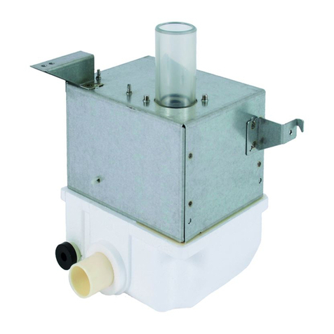
Drain pump unit
Fixture plate for
Drain pump unit
Hexagon bolt with
washer
(M6 × 12 )
Drain hose with
heat insulation
Fixture band
Hoseband
Elbow
Socket
Drainpipe
1
1
3
1
1
2
1
1
1
Outlet drain pipe
Inlet drain pipe
No. Part name Q’ty Shape
Support bracket
Tapping screw
(Ø4 × 10 )
(spare1)
Attachment plate
Heat insulation for
pipe
Heat insulation for
Elbow
Bandingband
Tapping screw
(Ø4.2 × 13 )
(spare1)
Fixture plate
1
4
1
1
1
3
2
1
spare 1
spare 1
()
()
+1E(1-6)TCBDP32DE.p65 2005/02/07, 14:22Page 2 AdobePageMaker6.5J/Win
ブラック
3
3
Installing Drain pump kit
• Unscrew the two screws on the left of the air conditioner, and secure the fixture plate for the Drain
pump unit using the two screws aligning the hole positions.
• Attach the Drain pump unit top plate to the air conditioner using the support bracket .
(Use the attached tapping screws and the air conditioner screws.)
• Secure the Drain pump unit using three hexagon bolts with washer.
4
Installing the Attachment plate
• Attach the attachment plate to the air conditioner at the position shown below.
• Use the attachment plate as a 5-degree ruler for the socket and drain pipe .
• To install the fixture band , unscrew the screw located 358 mm away from the drain port, and then
secure the fixture band with the screw. Drill a hole to the right with the tapping screws , and then
install the fixture.
(Since thread shearing may occur when an electric screwdriver is used, stop using it halfway and then
tighten the screw manually.)
358
24
45
60
48
31
24
Drain port
Drain pump unit
Air conditioner
Secure the attachment
plate with the removed
screws.
Drain port
+1E(1-6)TCBDP32DE.p65 2005/02/07, 14:22Page 3 AdobePageMaker6.5J/Win
ブラック
4
ENGLISH
5
Hose Connecting
Be sure to fix the center of the hose to the air conditioner cabinet with the fixture band to install
a drain trap. (Water leakage may occur without this inclination.)
REQUIREMENT
• Connect the elbow , drain pipe , and the socket to the drain port of the air conditioner. Use
adhesive for vinyl chloride to connect pipes.
• Install the elbow 5 degrees downward by tightening the socket to torque of 60 to 100 Nm to
provide an inclination for the hose for draining.
• Connect the socket to the Drain pump unit inlet pipe with the hose , and tighten both ends of the
hose with the hose bands .Insert the hose into the joint by approx. 25 mm.
• Insulate the vinyl chloride joint and the hose at the Drain pump unit connection portion with the heat
insulation for pipe and heat insulation for elbow .
Ensure heat insulation by taping at the insulator joint areas.
• Secure the fixture plate to the attachment plate with the tapping screw .
(Be sure to install this fixture plate as this is for ensuring an angle of 5 degrees.)
Be careful not to damage the Drain pump kit hose during handling before extending it because it
passes under the unit.
CAUTION
5˚
514
86 59
30
5˚
Outlet drain pipe
Fixture plate for
Drain pump unit
Tapping screw
Fixture plate
Heat insulation for elbow
Air conditioner
Drain pump unit
Heat insulation
for pipe
Taping Drain hose with heat
insulation
Fixture band Install drain hose trap
Taping
<Enlarged view of joint>
Socket
Drain pipe
Elbow
Less than 175
+1E(1-6)TCBDP32DE.p65 2005/02/07, 14:22Page 4 AdobePageMaker6.5J/Win
ブラック
5
31
31 31
31
6
Drain piping
• Be sure to tilt downward the drain pipe from the outlet drain pipe of the Drain pump unit.(Support and
secure the drain pipe so that it will not loose or slack to avoid stress to the outlet drain pipe.)
• Insulate the drain pipe with heat insulator (10 mm or more thick) without clearance to prevent water
leakage.
<Illustration for Connection>
7
Wire Connecting
Do not apply tension to the Drain pump unit and the connectors.
REQUIREMENT
• Detach the cover of electric parts box of the air conditioner.
• Plug the 3P connector (blue) of the Drain pump kit into CN068 (blue) in the box.
• Plug the 3P connector (red) of the Drain pump kit into CN030 (red) in the box.
* Disconnect the short-circuit connector from the P.C. board as it is not used.
(Clamp the cable in the electric parts box.)
Float switch
(FS)
P.C. board
To kit
Cable
CN030 (red)
CN068 (blue)
<Connection Diagram>
CN068 (blue) CN030 (red)
Drain pump
(DP)
+1E(1-6)TCBDP32DE.p65 2005/02/07, 14:22Page 5 AdobePageMaker6.5J/Win
ブラック
6
ENGLISH
8
Test Run
Checking drain status
Run the air conditioner in cooling mode after completion of electrical work and piping construction, and
check smooth draining.
• If long-time cooling is disabled, fill the drain pan of the air conditioner with water, and check for smooth
draining.
• Check that no water is leaking from anywhere.
Checking float switch
• To activate the float switch, detach the front panel of the kit and press up the float of the switch with
a screwdriver or similar instrument.
• Be careful that the air conditioner will stop abnormally if the float switch is operated continuously for
two minutes or more.
REQUIREMENTS
• Activate the float switch during cooling operation.
Check that the air conditioner stops cooling operation with the drain pump running.
• Activate the float switch after cooling operation.
Check that the air conditioner drains by the drain pump.
9
Check the Draining
In order to put the function of the air conditioner and the drain pump kit fully to practical use, the regular
maintenance and check are necessary, together with correct usage.
For the air conditioner body and the drain pump kit especially, check dirt of the drain pan once per year
before cooling season and clean them if dirt is heavy.
35
<Float switch position>
Float switch
+1E(1-6)TCBDP32DE.p65 2005/02/07, 14:22Page 6 AdobePageMaker6.5J/Win
ブラック

Other Toshiba Water Pump manuals

Toshiba TCB-DP31CE User manual

Toshiba

Toshiba TCB-DP31CE User manual

Toshiba TCB-DP31DE User manual

Toshiba

Toshiba TCB-DP31DE User manual

Popular Water Pump manuals by other brands

Greencut BOS12500 instruction manual

Greencut

Greencut BOS12500 instruction manual

EINHELL 41.801.35 operating instructions

EINHELL

EINHELL 41.801.35 operating instructions

Grizzly TRP 350 K Translation of the original instructions for use

Grizzly

Grizzly TRP 350 K Translation of the original instructions for use

Whale Gusher 30 Series Installation & user's instructions

Whale

Whale Gusher 30 Series Installation & user's instructions

Becker T 4.25 DV operating instructions

Becker

Becker T 4.25 DV operating instructions

CAT Pumps 3570 Series Service manual

CAT Pumps

CAT Pumps 3570 Series Service manual

Pentair WGX30 Installation and operation manual

Pentair

Pentair WGX30 Installation and operation manual

Briggs & Stratton AC0101 Series Illustrated parts list

Briggs & Stratton

Briggs & Stratton AC0101 Series Illustrated parts list

Accudyne Industries LMI ROYTRONIC EXCEL AD9 Series instruction manual

Accudyne Industries

Accudyne Industries LMI ROYTRONIC EXCEL AD9 Series instruction manual

GORMAN-RUPP PUMPS 80 Series Installation, operation, and maintenance manual with parts list

GORMAN-RUPP PUMPS

GORMAN-RUPP PUMPS 80 Series Installation, operation, and maintenance manual with parts list

Pfeiffer Vacuum UNO 35 operating instructions

Pfeiffer Vacuum

Pfeiffer Vacuum UNO 35 operating instructions

BWT PEARL HPT 09 instruction manual

BWT

BWT PEARL HPT 09 instruction manual

Samoa 560 230 Technical service guide

Samoa

Samoa 560 230 Technical service guide

Grundfos CM Installation and operating instructions

Grundfos

Grundfos CM Installation and operating instructions

ITT Goulds Pump 2AUW Installation, operation and troubleshooting instructions

ITT

ITT Goulds Pump 2AUW Installation, operation and troubleshooting instructions

WIKA CPP120-X operating instructions

WIKA

WIKA CPP120-X operating instructions

salmson ALTI-VE 18 Installation and starting instructions

salmson

salmson ALTI-VE 18 Installation and starting instructions

Triton T22i Installation and operating instructions

Triton

Triton T22i Installation and operating instructions

manuals.online logo
manuals.online logoBrands
  • About & Mission
  • Contact us
  • Privacy Policy
  • Terms and Conditions

Copyright 2025 Manuals.Online. All Rights Reserved.