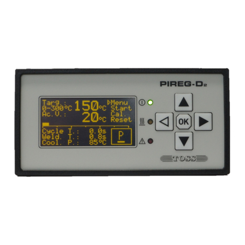
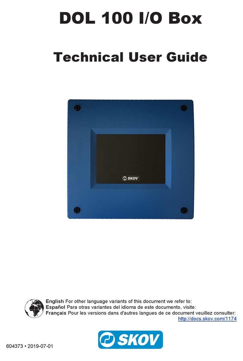
Toss PIREG-C2 Operating and installation instructions

16502 PIREG-C2 Gerätebeschreibung mit EtherNet_IP Bussystem191017 - EN.docx/ Page 1 of 66
1
PIREG-C2Device Description:
Resistance temperature controller
with EtherNet/IP interface
Applications:
Packaging machines for
sealing plastic foils
PIREG-C2 controller with EtherNet/IP
PIREG-CT-50 current transformer
EMV-Filter
Contents:
1. General, safety and warning instructions 2
1.1. Note on the device description 2
1.2. Icons and symbols 3
1.3. General safety instructions 3
1.4. Application 3
1.5. Note on the heating conductor 3
1.6. Note on the sealing transformer 4
1.7. Note on the current transformer 4
1.8. General assembly instructions 4
1.9. Maintenance 4
1.10. Validity 4
2. Short description 5
3. Operating states 5
3.1. Calibration 5
3.1.1. Initialisation 6
3.1.2. Calibrating the input amplifier 6
3.1.3. Determining the phase shift 6
3.1.4. Determining the reference resistance 6
3.1.5. Temperature comparison time 6
3.1.6. Checking the reference resistance 6
3.1.7. Determining the P-factor 6
3.1.8. 8-point Tc correction 6
3.1.9. Single-point Tc correction 8
3.1.10. P-factor correction 9
3.2. OFF state 9
3.2.1. Measurement pulse-pause 9
3.2.2. Calibration switching 9
3.3. ON state 9
3.4. Error state 9
3.4.1. Temperature monitoring 9
3.4.2. Heating monitoring 10
3.4.3. Communication monitoring 10
3.4.4. P-factor monitoring 10
3.4.5. Heating time limit 10
3.4.6. Error causes 10
3.4.7. Error memory 11
4. Operation 11
4.1. LEDs 11
4.1.1. Power 11
4.1.2. Heat 11
4.1.3. Calibration 11
4.1.4. Alarm 11
4.1.5. Bus system: 11
4.1.6. Network: 11
4.2. Inputs 11
4.2.1. Start input 11
4.2.2. Calibration start input 11
4.2.3. Reset input 12
4.2.4. Target value input 12
4.3. Outputs 12
4.3.1. Vref output 12
4.3.2. Actual value output 12
4.3.3. Alarm output 12
4.3.4. OK output 12
4.3.5. ELR output 12
4.4. Interfaces 13
4.4.1. RS232 and USB communication 13
4.4.2. Addressed RS232 communication 13
4.4.3. RS485 communication 13
4.4.4. RS232 com. with the TM6 thermom. 14
4.5. RS232 a. USB interface acknowledg. 15
4.5.1. OK acknowledgement 15
4.5.2. Error 1 acknowledgement 15
4.5.3. Error 2 acknowledgement 15
4.5.4. Error 3 acknowledgement 15
4.5.5. Error 4 acknowledgement 15
4.6. RS485 interface acknowledgements 16
4.6.1. OK acknowledgement 16
4.6.2. Command lock 16
4.6.3. Command error 16
4.6.4. Transfer error 16
4.6.5. Syntax or parameter error 16
4.7. Interface commands 17
4.7.1. AHUE command 17
4.7.2. BRAT command 18
4.7.3. BSTZ command 18
4.7.4. EINS command 18
4.7.5. EIPA command 19
4.7.6. FEKO command 21
4.7.7. FESL command 21

16502 PIREG-C2 Gerätebeschreibung mit EtherNet_IP Bussystem191017 - EN.docx/ Page 2 of 66
2
4.7.8. FESP command 22
4.7.9. FEZU command 23
4.7.10. GADR command 24
4.7.11. GTYP command 24
4.7.12. GWPA command 24
4.7.13. HZBG command 25
4.7.14. ISTW command 25
4.7.15. KANR command 26
4.7.16. KAPA command 26
4.7.17. KAPK command 27
4.7.18. KASR command 28
4.7.19. KOKO command 28
4.7.20. KONF command 29
4.7.21. KOUE command 30
4.7.22. KPFK command 30
4.7.23. KTKZ command 31
4.7.24. MEPA command 31
4.7.25. PFUE command 32
4.7.26. SOLW command 32
4.7.27. STEU command 33
4.7.28. STKA command 33
4.7.29. STRS command 34
4.7.30. STST command 34
4.7.31. TKEI command 34
4.7.32. TKEK command 35
4.7.33. TOKG command 35
4.7.34. TUEE command 36
4.7.35. UIMW command 36
4.7.36. VERS command 37
4.7.37. WESE command 37
4.7.38. ZUST command 38
4.7.39. ZYKL command 39
4.8. EtherNet/IP communication 41
4.9. Device data 41
4.10. Process data 42
4.10.1. Read process data, T O 42
4.10.2. Write process data, O T 42
4.10.3. Configuration parameters 43
4.11. Parameter data 43
4.11.1. AHUE parameter data 43
4.11.2. BSTZ parameter data 44
4.11.3. EINS parameter data 44
4.11.4. EIPA parameter data 45
4.11.5. FEKO Parameterdaten 46
4.11.6. GWPA parameter data 46
4.11.7. HZBG parameter data 46
4.11.8. KAPK parameter data 47
4.11.9. KASR parameter data 48
4.11.10. KONF parameter data 48
4.11.11. KPFK parameter data 49
4.11.12. KTKZ parameter data 50
4.11.13. PFUE parameter data 50
4.11.14. TKEK parameter data 50
4.11.15. TOKG parameter data 52
4.11.16. TUEE parameter data 53
4.11.17. VERS parameter data 53
4.11.18. WESE parameter data 53
4.11.19. ZYKL parameter data 54
4.12. EtherNet/IP reset 56
4.12.1 Power-on reset 56
4.12.2 Factory settings 56
4.13. Manual IP address 56
5. Installation and commissioning 57
5.1. Installation 57
5.2. 120/240V mains voltage changeover 57
5.3. Configuring the settings 57
5.4. Connecting the PIREG-C2 58
5.5. Control inputs 58
5.6. Connecting to the mains voltage 58
5.7. Burning in the heating conductor 58
5.8. When the contr. does not work corr. 58
6. The heating conductor 58
7. Technical data 60
7.1. Controller 60
7.2. Current transformer 62
7.3. Potentiometer 63
7.4. Analogue display 63
7.5. Sealing transformer 63
7.6. TM6 thermometer 63
7.7. Ordering codes 63
7.8 Housing 64
7.8.1. PIREG-C2 housing 64
7.8.2. Current transformer housing 64
7.8.3. Potentiometer housing 64
7.8.4. Analogue display housing 64
7.9. Spare parts 64
8. Connection diagrams 65
8.1. PIREG-C2 with ext. solid-state relay 65
8.2. PIREG-C2 with internal thyristors 65
8.3. RS232 / RS485 connection - interface 65
9. Application note 66
9.1. Application instructions 66
10. Disposal 66
1. General, safety and warning instructions
1.1. Note on the device description
The purpose of this device description is to ensure optimum installation, commissioning, operation and
maintenance of the PIREG-C2 and must be read prior to carrying out any of the actions described. Keep
the device description handy and accessible to all users for possible referencing. Pass this manual on to
future users of the PIREG-C2.
All necessary settings are described in this device description. Should difficulties nevertheless arise dur-
ing commissioning or operation, please do not carry out any unauthorised manipulations. You could put
yourself and others at risk as well as jeopardize your warranty claim. In such cases, please contact us
immediately:
GmbH & Co. KG Phone: +49 (0) 64 08 - 90 91 - 0
-Verpackungssysteme- Fax: +49 (0) 64 08 - 43 55
Danziger Straße 15 E-mail: info@toss-gmbh.de
D-35418 Alten-Buseck Internet: www.toss-gmbh.de

16502 PIREG-C2 Gerätebeschreibung mit EtherNet_IP Bussystem191017 - EN.docx/ Page 3 of 66
3
1.2. Icons and symbols
Danger (EN):Indicates a hazard that could result in personal injury. Whenever this symbol is
used, the device description must be consulted and the accompanying instructions must be
observed and followed in order to avoid hazards.
Danger (FR):Indique un danger pouvant entrainer des atteintes à la santé des personnes.
Lorsque ce symbole est utilisé, la description de l’appareil doit être consultée et les indications
doivent être observées et respectées afin d’éviter toute mise en danger.
Danger (EN):Indicates a hazard due to electrical current. Failure to observe the safety instruc-
tions may result in serious or fatal injuries.
Danger (FR):Indique un danger d’électrocution. Un non-respect de ces indications de sécurité
entraine un danger de blessures graves, voire mortelles.
Danger (EN):Indicates a hazard due to hot surfaces or burn up that could result in personal
injury.
Danger (FR):Indique un danger dû aux surfaces brûlantes, voire rougeoyantes pouvant en-
trainer des atteintes à la santé des personnes.
Note (EN):Indicates particularly important information which, if ignored, can lead to material
damage, for example.
Indications (FR):Indique une information particulièrement importante pouvant entrainer des
dégâts matériels en cas de non-respect.
1.3. General safety instructions
EN: The safety instructions and warnings given in this description must be followed to guaran-
tee safe operation of the equipment. The equipment can be operated without impairing the op-
erational reliability if the conditions stated in the technical specifications are observed.
The equipment may only be installed and started-up by suitably trained personnel.
Maintenance and repair of the equipment may only be carried out by trained personnel, who are
familiar with the dangers and guarantee conditions.
FR: Les indications et mises en garde contenues dans cette description doivent être respectées
afin de garantir un fonctionnement sûr. Si les consignes de sécurité de fonctionnement sont
respectées, l’appareil peut être exploité aux conditions mentionnées dans les données tech-
niques.
Cet appareil ne peut être installé et mis en service que par un personnel qualifié en technique
électronique !
Les travaux d’entretien et de réparation ne peuvent être effectués que par des personnes
formées et spécialistes familiarisées avec les dangers liés à l’appareil et les conditions de gar-
antie.
1.4. Application
EN: The PIREG-C2 resistance temperature controller may only be used for the heating and
temperature control of heating conductors as specified via isolating transformers in accordance
with the regulations, notes and warnings contained in this description.
Non-observance of the instructions or incorrect use of the equipment can result in impairment of
the safety or overheating of the heating conductor, the electrical wiring or the transformer.
FR: Le régulateur de température à résistance PIREG-C2 ne doit être utilisé que pour le chauf-
fage et la régulation de température de conducteurs de chaleur expressément conçus à cet
effet par l'intermédiaire de transformateurs de séparation conformément aux prescriptions, indi-
cations et mises en garde mentionnés dans cette description.
Le non-respect ou l'utilisation non conforme peut compromettre la sécurité ou entrainer le sur-
chauffe des conducteurs de chaleur, des câbles électriques, du transformateur, etc.
1.5. Note on the heating conductor
A basic precondition for the function and safe operation of the complete heating system is the application
of suitable heating conductors.
The positive temperature coefficient of the heating conductor used must be equal or greater than the
positive temperature coefficient set at the PIREG-C2. The appropriate temperature coefficient of the heat-
ing conductor must be set at the PIREG-C2 via the interfaces. The temperature coefficient of the heating
conductor must be positive over the entire temperature range.
Caution (EN):Using heating conductors with too low a temperature coefficient, or adjusting the
controller to a temperature coefficient that is too high, can result in uncontrolled overheating or
melting of the heating conductor.
Attention (FR):Si un conducteur de chaleur est utilisé avec un petit coefficient de température
ou qu’un coefficient de température trop grand est réglé sur le régulateur, les conducteurs de
chaleur vont chauffer de manière incontrôlée et peuvent aller jusqu’à fondre.
Heating conductors with a lower temperature coefficient can also be used when correcting the setpoint
voltage (4.1.3.).
Temperature regulation of heating conductors connected in parallel must be more precise than of heating
conductors connected in series. However, the wiring must be strictly symmetrical and performed in such a
way that no overcurrent arises when two heating conductors on opposite sides contact each other.

16502 PIREG-C2 Gerätebeschreibung mit EtherNet_IP Bussystem191017 - EN.docx/ Page 4 of 66
4
If series-connected heating conductors have to be used, the effect on the overcurrent reaction should be
taken into consideration if two opposite sealing bands touch each other.
1.6. Note on the sealing transformer
The sealing transformer must be configured according to EN 61558 (VDE 0570) resp. UL 5085 (isolating
transformer with reinforced isolation) and in a single-chamber design. All types and designs that comply
with the standards can be used as sealing transformers. The induction in the transformer's iron core must
not be reduced as is normally the case with primary side thyristor operation. A transformer with low losses
are disrupted less on the secondary side than with transformers that have low energizing currents. Thus
in applications with short heating and sealing times, stiff and generally larger transformers should be
used. Where a great deal of sealing is to be performed, a transformer with a primary voltage of 400 V is
advantageous, because this way, the switching capacity of the PIREG-C2's internal actuator is more likely
to be sufficient and an external actuator with solid-state relay will not have to be used.
Caution (EN):There must be sufficient protection against accidental contact if the transformer
is installed in a machine frame. Furthermore, ensure that water, cleaning liquids or conducting
liquids do not come into contact with the transformer. The conductor wiring cross sections
should be designed to match the actual currents. Non-observance of these notes may result in
impairment of the electrical safety.
Attention (FR):Si le transformateur est placé dans le corps de la machine, une protection
suffisante contre les contacts accidentels doit être prévue. De plus, il convient d’empêcher l'eau,
les solutions de nettoyage ou les liquides conducteurs d’entrer en contact avec le transfor-
mateur. Les sections des câbles doivent être conçues en fonction des courants réels. Le non-
respect de ces instructions compromet la sécurité électrique.
For best results, the transformer's performance and the secondary voltage must be suited to the heating
conductor. A short heat-up period is reached with of a high transformer output voltage. However, the volt-
age selected should not be too large so that not less than 12 controller measurements are needed for a
target temperature increase of 300°C when heating up (heat-up period 240 ms). For smaller heat-up
curves, correspondingly fewer measurements are necessary. (The PIREG-C2 takes a measurement eve-
ry 20 ms while heating).
The larger the transformer's secondary voltage for a given heating conductor, the more energy is fed into
the heating conductor, even in the OFF state. This is done by means of temperature measuring impulses,
which the controller regularly sends to the heating conductor. Therefore, the higher the secondary voltage
of the transformer the greater is the difference between the resting temperature and the ambient tempera-
ture in the OFF state.
1.7. Note on the current transformer
EN: The current transformer is an essential part of the control system. Only Toss current trans-
formers may be used. The current transformer may only be operated with ballast resistance.
The ballast resistance is integrated into the PIREG-C2. The current transformer must be mount-
ed in such a way that magnetic leakage fields from the sealing transformer or other leakage
fields do not affect the measurement.
FR: Le transformateur de courant fait partie du système de régulation. Seuls les transfor-
mateurs de courant Toss peuvent être utilisés. Le transformateur de courant ne doit être utilisé
qu'avec une résistance ohmique apparente. La résistance ohmique apparente est intégrée dans
le PIREG-C2. Le transformateur de courant doit être monté de telle sorte que les champs mag-
nétiques de dispersion du transformateur de soudage ou d'autres champs de dispersion n'influ-
encent pas la mesure.
Caution (EN):The used cable to the heating conductor can heat up the current transformer.
Attention (FR):Le conduit utilisé allant vers le conducteur de chaleur peut chauffer le transfor-
mateur de courant.
1.8. General assembly instructions
The PIREG-C2 resistance temperature controller is only suited for use in a switch cabinet. Open opera-
tion is not permitted.
The controller as well as the current transformer are mounted on 35mm mounting rails as per EN 60715
(EN 50022). When assembling the controller on the mounting rail, there must be a distance of at least 20
mm to the next device.
Heat dissipation from neighbouring devices must be taken into account (note the ambient temperature
specifications).
1.9. Maintenance
The PIREG-C2 resistance temperature controller does not require any special maintenance. However, an
occasional check or tightening of the connection terminals is recommended. Dust deposits on the control-
ler can be removed with dry compressed air once the power has been switched off.
1.10. Validity
The first device type (vw) delivered was the series 1.00 with the program version 1.01 for the electrically
separate side (ggg) and 1.01 for the instrumentation side (mmm). Supplements in this description which
are only valid from a later version and include the version, the notation Vvvv/ggg/mmm, e.g.

16502 PIREG-C2 Gerätebeschreibung mit EtherNet_IP Bussystem191017 - EN.docx/ Page 5 of 66
5
V1.00/1.01/1.01 from which they are valid. The device and program versions are read by command
(VERS) via the interfaces.
2. Short description
The PIREG-C2 resistance temperature controller with an EtherNet/IP interface as bus system is used to
control the temperature of heating conductors for the heat-impulse sealing of foils. The sealing transform-
er is used by the PIREG-C2 on the primary side. The internal actuator or an external solid-state relay
which is controlled by the PIREG-C2 can be used. The heating conductor is fed from the secondary side
of the transformer. The measuring signals are received directly at the heating conductor and are made
available to the controller.
The temperature coefficient Tc of the heating conductor must be positive. This increases the resistance of
the heating conductor when heated. This effect is used for temperature control. The temperature control-
ler measures and regulates the resistance of the heating conductor. The temperature coefficient Tc is a
material constant that depends on the alloy used for the heating conductor. The actual temperature is
determined by measuring the voltage and current.
The PIREG-C2 operates as a proportional control unit that independently determines the P-factor (the
control amplification) for the controlled system of a process during calibration itself. The controlled system
consists of a sealing transformer and a heating conductor. The P-factor determined during calibration can
afterwards still be corrected by command or via the target value input (4.7. and 4.11.). An additional
compensation function allows to minimise the permanent control deviation typical of a proportional con-
troller.
The PIREG-C2 is operated either conventionally with a setpoint potentiometer or setpoint voltage, actual
value instrument, LEDs and switches or digital signals (4.1. - 4.3.), or via the EtherNet/IP interface, the
RS232, RS485 or USB interface (4.4. –4.13.) with which the PIREG-C2 is equipped. The PIREG-C2
can only be set via the EtherNet/IP interface or the RS232, RS485 or USB interface. Combinations of
both types of operation are possible.
The PIREG-C2 is set to the temperature coefficients (4.7. and 4.11.). If the temperature coefficient
values differ, the setpoint voltage must be corrected. The PIREG-C2 can also determine the actual tem-
perature coefficient of a heating conductor itself by means of a temperature coefficient correction (Tc
correction) (4.7. and 4.11.). Connect the PIREG-C2 via the RS232 interface to an external TM6 ther-
mometer which measures the actual temperature of the heating conductor to simplify the Tc correction.
Depending on the setting, the PIREG-C2 can operate up to a temperature range of 500 °C.
During calibration, the controller sets itself to the secondary voltage of the transformer and the current
through the heating conductor. The secondary voltage of the transformer may be within a range of 1...120
V. The current measured with a current transformer can range from 20 to 500 A. The calibration values
can be stored in the controller, so that there is no need for renewed calibration and start-up time after
switching on the power when conditions have not changed.
The PIREG-C2 can conduct the calibration at room temperature (always taken to be 20°C) as well as at
any other ambient temperature between 0 - 50 °C. The controlled is informed of the actual reference tem-
perature from outside. This is advantageous in the case of constant sealing temperatures with different
environmental conditions(4.7.8 and 4.11.).
High quality sealing transformers, such as toroidal core transformers, are switched by the PIREG-C2 on
the primary side. A smooth switching procedure is employed that compensates for the remanence of the
sealing transformer. An initialising remanence setting is made automatically after switching on the power
and following calibration. Only a short remanence setting lasting 40 ms for El core transformers and 80
ms for toroidal core transformers is needed before each sealing process. If, with toroidal core transform-
ers, the pause between two sealing processes is longer than 10 minutes, the remanence setting takes
160 ms. The remanence is the residual magnetization in the transformer's iron core. During the initial
remanence setting procedure, the heating conductor has to be heated for a short time to approx. 40 to 70
C. The PIREG-C2 itself uses a phase angle controller to regulate the temperature.
3. Operating states
3.1. Calibration
During calibration, the PIREG-C2 automatically adapts to the sealing transformer/heating conductor com-
bination. At the same time, the voltage "Vr" at the heating conductor and the current "Ir" through the heat-
ing conductor are measured every second. In this condition, the blue "calibration" LED is lit up and the
calibration OK signal is reset. The calibration OK signal is sent by the OK output if the appropriate func-
tion has been set by command (KONF). The OK output is factory set to the Calibration-OK message fea-
ture. The actual value output is used to display the individual steps. The actual value output is updated
every second.
The calibration procedure with the individual states is available as data at the EtherNet/IP interface and
the other interfaces. The controlling PLC can additionally track the calibration process by observing the
actual value output at terminal 17 and can recognise the end of the calibration from the calibration OK
signal. The sealing controls are then released. During calibration steps 1 to 7, no "Start" signal may be
given as otherwise the PIREG-C2 will interrupt the calibration with error 2.

16502 PIREG-C2 Gerätebeschreibung mit EtherNet_IP Bussystem191017 - EN.docx/ Page 6 of 66
6
The calibration process will undergo the following steps:
3.1.1. Initialisation: During initialisation, the PIREG-C2 determines the data necessary for calibration. In
addition, it checks the selected temperature coefficient for dynamics and continuity in the selected tem-
perature range. Should the dynamics and continuity exceed the permitted limits, the PIREG-C2 will stop
the calibration procedure with Error 13 (parameter error). The reference temperature still set is checked in
the permitted range of 0…50 °C. If the reference temperature is outside this range, the PIREG-C2 will
also stop the calibration procedure with Error 13 (reference temperature selected too large).
3.1.2. Calibrating the input amplifier: The input amplifiers for Vr and Ir are adjusted in steps to the volt-
age and current at the heating conductor. In the first step, the required modulation reserve for the sealing
transformer/heating conductor combination is determined automatically if not set manually by command
(KASR).
During this step, different voltage values are applied to the actual value output every second. The meas-
ured current or voltage value is connected alternately. The measured value of the current is displayed in
the 0 - 5 V range, the voltage in the 5 - 10 V range. The zero point of the measured values is 5 V. At the
beginning of the calibration, the amplifiers (for Vr and Ir) are initialised with minimum amplification. At the
end of the calibration procedure, if the adjustment has been made successfully, the range for the dis-
played current value is from 1.66 - 3.33 V and the range for the displayed voltage value is from 6.66 -
8.33 V.
3.1.3. Determining the phase shift: During this step, the transformer-dependent phase shift between Vr
and Ir is measured and corrected. The controller automatically sets the optimum scan times for Vr and Ir.
The actual value output displays the phase shift. A signal of approx. 5 V corresponds to the ideal value.
3.1.4. Determining the reference resistance: (4.7. and 4.11.) The reference resistance of the heating
conductor (Rref) is determined in this step. The controller assumes a constant reference temperature of
20 °C for calibration. Alternatively, a variable reference temperature of 0...50 °C can be entered as nomi-
nal value (50 °C = 1.66 V at 300 °C and 1.00 V at 500 °C). While the calibration is being initialised, the
PIREG-C2 reads the variable reference temperature, depending on the settings. During calibration, the
heating conductor must be at the reference temperature to ensure that regulation is exact. By standardiz-
ing the voltage signal (Vr) and the current signal (Ir), the reference resistance for the different temperature
coefficients is always within the same resistance range. If 20 °C has been selected as the reference tem-
perature, then heating conductor's R20 is directly determined as the reference resistance. If a heating
conductor temperature other than 20 °C has been selected for calibration, then the determined reference
resistance corresponds to the temperature coefficient above or below the value for the R20. The refer-
ence resistance is displayed for one second at calibration stage 4 at the actual value output. At a refer-
ence temperature of 20 °C, the voltage at the actual value output is 7…8 V. At a variable reference tem-
perature the voltage will be between 6 and 10V.
3.1.5. Temperature comparison time: (4.7. and 4.11.) The aim of the temperature comparison time is
to ensure that the comparator resistance can only be determined when the heating conductor has com-
pletely cooled down. During this comparison time, the signal at the actual value output declines from 10 V
to 0 V. Times of 15 or 30 s can be chosen for the temperature comparison time.
3.1.6. Checking the reference resistance: The comparator resistance is checked after the temperature
reference time is finished. If calibration takes place on a heating conductor that has cooled down still fur-
ther during the temperature comparison time, the entire calibration will be discarded and the procedure
automatically restarted. Once the reference resistance has been successfully checked, the PIREG-C2
calculates the R20 (resistance at 20 C) of the heating conductor from the type of reference temperature
set, the temperature coefficients selected and the reference resistance (Rref) determined.
The comparator resistance measured is displayed for one second at the actual value output. The same
voltage must be set at the actual value output as when the reference resistance was determined (
3.1.4).
3.1.7. Determining the P-factor: The P-factor of the sealing transformer/heating conductor combination
is determined by heating with a constant correction variable. The heating conductor is either warmed by a
maximum of approx. 60 K or charged for a maximum of 120 network periods with a defined control value.
The total amplification of the control system is calculated from the measurement of the power fed into the
heating conductor and the measurement of the temperature increase of the heating conductor. The P-
factor for the PIREG-C2 is calculated from this.
In the case of adverse conditions of the sealing transformer/heating conductor combinations or the public
supply the P-factor of the PIREG-C2 can be corrected manually within a range of 30…110 % (4.7. and
4.8.).
The P-factor monitoring which is set by command (PFUE) is used to monitor the P-factor determined by
PIREG-C2 on a valid range (3.4.4., 4.7. and 4.11.).
3.1.8. 8-point Tc correction: The 8-point temperature coefficient correction function can be used to cor-
rect tolerances of the temperature coefficients. These result from the dispersion of the metallurgical com-
position of the heating conductors.

16502 PIREG-C2 Gerätebeschreibung mit EtherNet_IP Bussystem191017 - EN.docx/ Page 7 of 66
7
In calibration stage 8, the PIREG-C2 gradually heats up the heating conductor in eight temperature in-
crements or stages. The PIREG-C2 compares its actual value temperature with the actual temperature of
the heating conductor, which it receives as a target value or directly as a measured temperature value.
The size of each increment is a result of the selected temperature range. The first temperature increment
is always 50 °C. The temperature of the eighth temperature increment falls 20% below the final value of
the temperature range. The six other temperature increments are equidistant between these points. For
the300 °C temperature range, this results in the following temperatures: 50, 77, 104, 131, 159, 186, 213
and 240 °C. For the 500 °C temperature range, this results in the following temperatures: 50, 100, 150,
200, 250, 300, 350 and 400 °C.
The actual temperature of the heating conductor must be sent back externally to the PIREG-C2 as a tar-
get value or directly as a measured value of the TM6 thermometer. Deviations of up to ±20 % between
the calculated actual value temperature and the actual temperature of the heating conductor can be cor-
rected (4.1.9., 4.7. and 4.11.). The correction process is controlled with the “Start” signal or by com-
mand (STST).
The 8-point Tc correction can be saved by command (STKA) so that it doesn't need to be repeated after
a new calibration but only when the heating conductor is replaced.
Performing the 8-point Tc correction:
- manual operation: The actual temperature of the heating conductor is reported back to the PIREG-C2
via the set value input. The next temperature step is switched to with the rising edge of the “Start” signal.
After the heating conductor has reached a uniform temperature the temperature set as the target value is
taken over as the actual temperature of the heating conductor with the falling edge of the “Start” signal.
After heating to the next temperature stage, only accept the temperature once the heating conductor itself
has reached the specified temperature. The actual value output indicates the corresponding, not yet cor-
rected actual value temperature of the PIREG-C2.
At the beginning of the 8-point Tc correction, the "Calibration" LED flashes for 5 seconds at a cycle rate of
1 Hz, while the PIREG-C2 tries to establish the connection to the TM6 thermometer.
- manual operation with the TM6 thermometer: The 8-point Tc correction is controlled with the “Start”
signal as described above. The actual temperature of the heating conductor is measured with the TM6
thermometer which is connected to the RS232 interface of the PIREG-C2. The PIREG-C2 automatically
tries to establish a connection with the TM6 thermometer for 5 seconds at the beginning of the 8-point Tc
correction. The "Calibration" LED flashes at a cycle rate of 1 Hz during connection establishment and
when the connection to the TM6 thermometer has been established.
- automatic 8-point Tc correction: The PIREG-C2 must be connected to the TM6 thermometer and the
set value for the heating time must be greater than zero for the automatic 8-point Tc correction. The heat-
ing time is the period until the heating conductor has reached a uniform temperature at a temperature
stage. The heating time is set either in the Reset state or by command (KTKZ) (4.7. and 4.8.). The
PIREG-C2 undergoes the automatic 8-point Tc correction independently and remains at each tempera-
ture stage for the preset heating time.
Figure 1: Calibration process
The controller must undergo calibration steps one to seven for each calibration. Step eight is a selectable
calibration function (3.1.8.). If an error occurs during the individual calibration steps, the PIREG-C2
stops the calibration process and then restarts the calibration. Calibration is stopped with an error mes-
sage after attempt five was not successful (3.4.).
Calibration must be carried out when the heating conductor has reached a temperature of approx. 20 °C
or the externally determined calibration temperature to ensure that the R20 reference resistance of the

16502 PIREG-C2 Gerätebeschreibung mit EtherNet_IP Bussystem191017 - EN.docx/ Page 8 of 66
8
heating conductor is calculated correctly. The time required for a calibration process depends on various
factors. The calibration duration is determined by the voltage at the heating conductor, the current flowing
through the conductor, the phase shift from Vr and Ir and the P-factor of the sealing transformer/heating
conductor combination. The controller needs maximum 48 or 63 seconds for one calibration process.
If the calibration process is not successful, e.g. because the P-factor has been determined incorrectly, the
controller makes another four attempts before reporting an error. In this case, the maximum calibration
time can amount to 240 or 315 s, depending on the temperature comparison time.
If the calibration mode “new calibration” is chosen, the controller always switches to calibration immedi-
ately after a power-on or after a reset and carries out a new calibration. Calibration can also be started in
the OFF or error state with the signal “Calibration Start”.
If the calibration mode “Save” is chosen, the controller switches to calibration when in an OFF or error
state or before power-on only when the “Calibration Start” signal is applied. In this type of calibration, the
calibration values are saved in a non-volatile memory and are loaded immediately after a power-on or the
“Reset" signal.
The operator or the controlling PLC can recognize the end of a successful calibration process as follows:
- without 8-point Tc correction: By observing the actual value on the characteristic voltage curves (see
Fig.1, steps 5, 6 and 7 with subsequent remanence and subsequent cooling of the heating conductor
from approx. 50 °C to approx. ambient temperature).
- with 8-point Tc correction: As before, but with subsequent 8-point Tc correction (see step 8). After the
last correction step, the controller is ready for operation. The PLC must then wait until the temperature of
the heating conductor has cooled down.
- with calibration OK message: The calibration OK message is reset when calibration is started and
reset at the end of successful calibration. The calibration OK message is the factory setting of the OK
output, which can be changed by command (KONF).
3.1.9. Single-point Tc correction: With the single-point temperature coefficient correction the tolerances
of the temperature coefficient of the heating conductor can be corrected for just one operating point. For
this operating point the actual temperature of the heating conductor is reported back to the PIREG-C2 as
actual value or directly as measured value of the TM6 thermometer from outside. The single-point Tc
correction is carried out outside the standard calibration and is started from the OFF state. Single-point Tc
correction has an OFF and an ON state. After the single-point Tc correction was started, the PIREG-C2 is
in the OFF state. When the PIREG-D is in the ON state, the heating conductor is heated to the tempera-
ture which was set as target value in the OFF state. After heating, only accept the temperature once the
heating conductor itself has reached the specified temperature. The actual value output indicates the not
yet corrected actual value temperature of the PIREG-C2. The single-point Tc correction finishes upon
exiting the ON state. The correction process is controlled with the “Start” signal or by command (STST).
Deviations of up to ±20 % between the calculated actual value temperature and the actual temperature of
the heating conductor can be corrected. The single-point Tc correction can only be performed if an 8-
point Tc correction was not carried out during calibration. The single-point Tc correction is reset at each
calibration.
The single-point Tc correction can be saved by command (STKA) so that it doesn't need to be repeated
after a new calibration but only when the heating conductor is replaced.
Performing the single-point Tc correction:
- manual operation: The single-point Tc correction is started by command (STKA). If the pulse-control
was configured by command (KONF) for the calibration start input (5), the single-point Tc correction can
also be started by applying a high signal for less than one second (4.7. and 4.11.). The PIREG-C2
retains the temperature set as set value as the temperature of the operating point as long as a low-signal
is applied as “Start” signal. When a high signal is applied as “Start” signal the PIREG-C2 heats the heat-
ing conductor to the temperature of the operating point. Now the actual temperature of the heating con-
ductor is set as target value. When a low-signal is applied again as "Start” signal, the PIREG-C2 calcu-
lates the correction factors for the single-point Tc correction and saves these values if "Save" was select-
ed as the calibration type.
- manual operation with the TM6 thermometer: The single-point Tc correction is started and controlled
as described above. The actual temperature of the heating conductor is measured with the TM6 ther-
mometer which is connected to the RS232 interface of the PIREG-C2. The PIREG-C2 automatically tries
to establish a connection with the TM6 thermometer at the beginning of the single-point Tc correction The
Calibration LED flashes at a cycle rate of 1 Hz when connection to the TM6 thermometer has been estab-
lished.
- automatic single-point Tc correction: The PIREG-C2 must be connected to the TM6 thermometer
and the set value for the heating time must be greater than zero for the automatic single-point Tc correc-
tion. The heating time is the period until the heating conductor has reached a uniform temperature in the
ON state of the single-point Tc correction. The heating time is set either in the Reset state or by com-
mand (KTKZ) (4.7. and 4.11.). Automatic single-point Tc correction is started as described above for
manual operation. The PIREG-C2 undergoes the automatic single-point Tc correction independently and
remains in the ON state for the preset heating time.

16502 PIREG-C2 Gerätebeschreibung mit EtherNet_IP Bussystem191017 - EN.docx/ Page 9 of 66
9
3.1.10. P-factor correction: The P-factor correction is used for subsequent manual correction of the
calibrated P-factor (3.1.7.) in the case of very unfavourable conditions of the sealing transform-
er/heating conductor combinations or the public supply. The correction range is 30…110 %.
The P-factor correction can be set by command (KPFK). The P-factor correction value will not be reset
during a calibration as it is system dependent.
3.2. OFF state
In the OFF state, the PIREG-C2 regularly measures the resistance of the heating conductor and from this
value determines the temperature and forwards this to the actual value output.
For each resistance measurement a positive and negative power line half-wave of the same fixed angle
of current flow (1.8 ms at 50 Hz mains frequency) is applied to the transformer. The time intervals of the
measurements depend on the temperature of the heating conductor. When the heating conductor has
reached a temperature of 20 °C, the measuring interval is 1.5 s. At a temperature of 300 °C, the measur-
ing interval is only 100 ms.
The heating conductor is heated in the OFF state and dependent on the voltage by the energy introduced
when measuring the resistance.
The controller switches from the OFF state to the ON state as soon as the “Start” signal is applied. When
the "Calibration Start" signal is applied the PIREG-C2 returns to calibration and to the OFF state after the
end of a successful calibration. The PIREG-C2 then stays in the OFF state even when the "Calibration
Start" signal is still applied (evaluation of the rising edge).
If the pulse control was configured by command (KONF) for the calibration start input (5), the PIREG-C2
switches in the single-point Tc correction when a high-signal is applied for less than one second.
3.2.1. Measurement pulse-pause: In the off state, the measurement pulse-pause can be switched on
and off per command (MEPA). When measurement pulse-pause is activated, the PIREG-C2 stops send-
ing measurement pulses to the sealing transformer in order to determine the temperature of the heating
conductor.
The actual value output indicates the value determined last. Only the monitoring of the mains voltage and
the device function is still active. All other monitoring functions that relate to the measurement pulses are
disabled.
The measurement pulse-pause is for applications in which the primary or secondary circuit of the sealing
transformer has to be interrupted during operation without the PIREG-C2 switching to the error state.
With the start of a sealing process, a calibration or a reset, the measurement pulse-pause is automatically
terminated.
3.2.2. Calibration switching: The PIREG-C2 offers the possibility to save eight calibrations and to switch
between them by command (KANR). In the off state, a changeover between the eight calibrations is
made by command (KANR). Calibration 1 is always active after power on or reset.
The heating conductors of the eight calibrations must be the equal for the temperature coefficient, tem-
perature range and the other calibration settings. A possible temperature coefficient correction is per-
formed separately for each calibration. The PIREG-C2 performs its own calibration for each heat conduc-
tor, which is also stored separately.
3.3. ON state
In the ON state, the PIREG-C2 controls the temperature of the heating conductor in accordance with the
target value. A phase angle controller is used. The controller returns to the OFF state when the “Start”
signal is removed.
3.4. Error state
The error state is indicated on the PIREG-C2 only when an error occurs. The controller monitors the line
voltage, the temperature of the heating conductor, the values of the voltage and current measurements at
the heating conductor and the calibration parameters.
The alarm output is set in the error state. In the event of a power line error (error 3), actuation takes place
with a delay of 2 seconds. In the error state, the alarm and calibration LED’s are triggered with different
cycle rates of 1 or 4 Hz depending on the error that has occurred (see Table 1). The actual value output is
also cycled in some error cases. The voltage at the actual value output then changes every second be-
tween the voltages applicable to the different errors (see table 1). The error state can only be cancelled
by switching off the power supply, the „Reset“ signal and „Calibration Start“. With errors 1 and 3 the error
state cannot be cancelled with the "Calibration Start" signal.
In the OFF state, after switching on the power or following a reset, errors 4 - 13 are only reported by the
LEDs and actual value output; however, the alarm output is not set in the factory default. This way, a cali-
bration error does not lead to a machine malfunction when switching on. The factory setting can be
changed with a command (KONF).
3.4.1. Temperature monitoring: The monitoring of the temperature is an additional monitoring function
which is activated and adjusted with a command (TUEE). The actual temperature value is monitored dur-
ing the sealing process in the ON state to ensure that it is within a temperature OK range. If the actual
value leaves the temperature OK range during the sealing process after the stabilisation time has ended
the PIREG-C2 will go to error state with error 8. In the event of a change of the target value by more than
2 °C, the stabilisation period is restarted.

16502 PIREG-C2 Gerätebeschreibung mit EtherNet_IP Bussystem191017 - EN.docx/ Page 10 of 66
10
3.4.2. Heating monitoring: The monitoring of the heating is an additional monitoring function which is
activated and adjusted with the command (AHUE). With this function the temperature rise is monitored
after the “Start" signal was applied.
- Variant 1: Under variant 1, the PIREG-C2 monitors the heating time to a maximum value. If the actual
value of the temperature does not reach the temperature OK range within the set heating time, the
PIREG-C2 switches to the error state with error 8.
- Variant 2: Under variant 2, the PIREG-C2 monitors the heating time to a minimum and maximum value.
If the actual value of the temperature does not reach the temperature OK range within the set time win-
dow, the PIREG-C2 switches to the error state with error 8.
3.4.3. Communication monitoring: The monitoring of the communication is an additional monitoring
function for the three interfaces of the PIREG-C2 and is activated and set with a command (KOUE) for
each interface individually. This function monitors communication via the interfaces for interruptions. If the
communication via the interface is interrupted for a longer time than the set downtime, then the PIREG-
C2 switches to the error state with error 9.
3.4.4. P-factor monitoring: The P-factor monitoring is an additional monitoring function for the calibrated
P-factor (3.1.7.), which is set with a command (PFUE). This function is used to monitor the calibrated
P-factor for a minimum and maximum value of an OK range. If the calibrated P-factor is outside the OK
range, the PIREG-C2 will go to the error state with error 10.
A calibration with the intended sealing transformer/heating conductor combination should first be carried
out to determine the OK range of the P-factor monitoring. The calibrated P-factor of PIREG-C2 can be
read back by command (PFUE). The upper and lower limits should be set according to this value. In addi-
tion to the sealing transformer/heating conductor combination, the level of the mains voltage during cali-
bration has an impact on the calibrated P-factor of PIREG-C2. In the P-factor monitoring, the P-factor
correction (4.7. and 4.11.) is taken into account since the corrected P-factor is evaluated.
3.4.5. Heating time limit: The heating time limit is a monitoring function to prevent unintentional continu-
ous heating of the PIREG-C2 due to an operating error. A command (HZBG) activates the monitoring
function and sets the maximum heating time. If the set maximum heating time is exceeded in the ON
state, the PIREG-C2 goes to error state with error 2 and stops heating.
3.4.6. Error causes: Table 1
No.
Error
Actual
value
output
Alarm
LED
(red)
Calibr.
LED
(blue)
Alarm output
after
reset
after
“start”
signal
1
Device error or bus system supply voltage
too low or too high
4.66 / 0 V
on
off
set
2
- internal error or
- read-write error in the non-volatile memory
- or “start” signal during calibration
- or heating time limit
4.00 V
on
off
set
3
power line error (under-/overvoltage or line
frequency error)
3.33 V
on
4 Hz
set
4
current signal Ir and voltage signal Vr too
low
2.00 V
on
1 Hz
not set
set
5
voltage signal Vr too low
1.33 V
on
1 Hz
not set
set
6
current signal Ir too low
0.66 V
on
1 Hz
not set
set
7
current and/or voltage signal too high
5.33<>10 V
4 Hz
1 Hz
not set
set
8
temperature too low or too high (heating
conductor error), temperature monitoring or
heating monitoring,
temperature jump downwards or upwards
2.66 V
on
on
not set
set
9
data error, stored calibration values do not
match setting or communication monitoring
6.00<>10 V
4 Hz
4 Hz
not set
set
calibration not possible because
10
- current signal Ir and voltage signal Vr are
too low or too high or
- R20 cannot be determined or
- the phase shift or
- the P-factor cannot be determined;
- the P-factor monitoring has triggered
8.00<>10 V
1 Hz
4 Hz
not set
set
11
- voltage signal Vr too low or too high or
unstable
7.33<>10 V
1 Hz
1 Hz
not set
set

16502 PIREG-C2 Gerätebeschreibung mit EtherNet_IP Bussystem191017 - EN.docx/ Page 11 of 66
11
12
- current signal Ir too low or too high or un-
stable
6.66<>10 V
1 Hz
1 Hz
not set
set
13
- the selected reference temperature is too
high or
- the temperature coefficient correction
range exceeded or
- parameter error: continuity and dynamics
of the selected temperature coefficients in
relation to the temperature range.
8.66<>10 V
1 Hz
4 Hz
not set
set
3.4.7. Error memory: The PIREG-C2 has an error memory in which the last 100 error events are stored.
The error memory can be read out by command (FESP) and cleared by command (FESL). The respec-
tive error event is stored together with the value of the operating hours counter at the time of the error, so
it can be linked to a time.
4. Operation
The PIREG-C2 offers two means of operation. One is conventional operation with setpoint potentiometer
or setpoint voltage, actual value instrument or actual voltage value, switches or digital signals and LEDs.
The other is extended operation via EtherNet/IP interface or the RS232 (1), RS485 (2) and USB interfac-
es (3), with which the PIREG-C2 is equipped. The PIREG-C2 can only be set via the EtherNet/IP inter-
face or the RS232, RS485 or USB interface. Combinations of both types of operation are possible.
4.1. LEDs
4.1.1. Power:
The green Power LED indicates that the PIREG-C2 is connected to the line
voltage.
After switching on or resetting, the mains LED flashes at 1Hz for 5s if inter-
face control is selected for the temperature setpoint or setting control, see
command KONF.
4.1.2. Heat:
The yellow Heat LED is directly connected in parallel to the controller's actu-
ator. The brightness of this LED is directly proportional to the energy in the
heating conductor.
4.1.3. Calibration:
The blue calibration LED lights continuously during calibration and is used
for indicating errors. If there is a connection to the TM6 thermometer during
calibration or the single-point Tc correction, the LED will flash with 1 Hz.
4.1.4. Alarm:
The red Alarm LED, together with the yellow calibration LED, indicates re-
sistance temperature controller errors.
4.1.5. Bus system:
The two-colour, green and red LED bus system indicates the following
states of the EtherNet/IP interface used as bus system in the PIREG-C2:
Off: No bus system supply voltage
Green: Control by a scanner in RUN state
Green, flashing:Not configured or the scanner is in IDLE state
Red: Grave error (EXCEPTION state, serious error, etc.)
Red, flashing: Resettable error. Bus system is configured, but the stored
parameters differ from the parameters currently in use.
4.1.6. Network:
The two-colour green and red LED network indicates the following states of
the bus system network:
Off: No bus system supply voltage or no IP address
Green: Online, one or more connections are established (CIP class
1 or 3)
Green, flashing:Online, no connection is established
Red: Duplicate IP address, serious error
Red, flashing: One or more connections have a timeout (CIP class 1 or 3)
4.2. Inputs
4.2.1. Start input: The sealing process is initiated by applying a high signal to the start input (6). The
controller begins to set the temperature of the heating conductor to the set value temperature and main-
tains this temperature constantly as long as a high signal is applied to the start input.
If 8-point Tc correction is selected for calibration, the correction process is also controlled by the start
input for manual operation. The single-point Tc correction is also controlled by the start input.
4.2.2. Calibration start input: When a high signal is applied to the calibration start input (5) in the OFF or
error state of the controller, it switches to the calibration state. Normally the controller is adapted to the
sealing transformer/heating conductor combination. During calibration of the controller the signal can be
switched back to Low.
The calibration start input can also be configured for pulse control by command (KONF). The single-point
Tc correction can be started in this way in the OFF state when a high signal is applied to the calibration
start input for less than one second. If the high signal is applied for more than one second, the PIREG-C2
switches in the calibration state.

16502 PIREG-C2 Gerätebeschreibung mit EtherNet_IP Bussystem191017 - EN.docx/ Page 12 of 66
12
4.2.3. Reset input: When a high signal is applied to the reset input (7), the PIREG-C2 is reset to the state
after power-on. This allows you to leave the error state without switching off the mains voltage. It can also
be used to cancel a calibration in progress.
4.2.4. Target value input: The temperature setpoint of the controller is applied to the target value input
(16) with an analogue voltage. For a calibration with variable reference temperature, the reference tem-
perature is applied to the target value input and for the 8-point and single-point Tc correction, the actual
temperature of the heating conductor is applied. The voltage range of the target value input is 0 - 10 V.
The selected temperature range applies to the maximum target voltage i.e. 10 V at the target value input
correspond to 300 °C or 500 °C in the temperature range 300 °C or 500 °C.
A potentiometer can also be used for the setpoint, whose sliding contact is connected to the target value
input, the CW connection to the Vref output (15) and the CCW connection to the corresponding GND con-
nection (13). When connecting the setpoint potentiometer, pay attention to the direction of rotation of the
potentiometer. The voltage at the target value input should increase when turning the setpoint potentiom-
eter clockwise (CW).
4.3. Outputs
4.3.1. Vref output: The Vref output (15) provides a reference voltage of +10 V needed to obtain the set
value using a potentiometer. Should the PIREG-C2 be operated without an additional power supply, the
switches for the control inputs can also be connected to the Vref output. The Vref output can supply a
maximum current of 20 mA.
4.3.2. Actual value output: The actual value output (17) supplies a voltage in the range 0 - 10 V, propor-
tional to the temperature of the heating conductor. The voltage range relates to the selected temperature
range. In other words, 10 V at the target value input corresponds to 300 °C or 500 °C. The actual value
output can supply a current of max. 5 mA.
- Hold mode: When the Hold mode is activated by command (KONF), the temperature measured at the
end of the sealing process is also displayed at the actual value output in the OFF state. You can select
whether the measured temperature is only displayed for 2 seconds or until the following sealing process
is started.
4.3.3. Alarm output: The alarm output (12/18) is a relay switching contact. A command (KONF) can be
used to set whether the alarm output is opened or closed in the case of a fault. The factory setting of the
relay contact is “closed” when a fault occurs. In the event of a power line error (error 3), it is set with a
delay of 2 s, for all other errors immediately.
In addition, the SKONF command can be used to specify whether the alarm output should be set imme-
diately in the event of an error or only after the sealing process has been performed. This way, a calibra-
tion error does not lead to a machine malfunction when switching on.
4.3.4. OK output: The OK output (21/22) is a relay switching contact. A command (KONF) can be used
to set whether the OK output is opened or closed if the situation is OK. When supplied from the factory,
the relay contact is closed in the OK case. The OK output has the following actuation functions, which can
be specified by command (KONF):
- Calibration OK message: This is the factory setting. The OK output is reset during calibration. It is set
again after a successful calibration. End of calibration is indicated with the calibration OK message. If the
stored calibration values do not match the setting, the OK output is also reset.
- Temperature OK message: The OK output is activated if the actual value is within the temperature OK
range. The temperature OK range and corresponding stabilising time are set by a specific command
(TOKG).
- Combination of calibration and temperature OK message: This is the combination of the two func-
tions above. This means that the calibration OK message is sent following a reset or a calibration pro-
cess, and the temperature OK message is sent after the first "Start" signal.
- Temperature reached message: If the actual value reaches 95% of the setpoint temperature in the ON
state, the OK output is activated. When leaving the ON state, the OK output is reset.
4.3.5. ELR output: The ELR output (19/20) controls an external solid-state relay which is used as actua-
tor instead of the internal actuator of the controller. Combinations of heating conductor and sealing trans-
former which have a greater capacity than the maximum permissible capacity of the internal actuator can
be switched with the external solid-state relay.

16502 PIREG-C2 Gerätebeschreibung mit EtherNet_IP Bussystem191017 - EN.docx/ Page 13 of 66
13
4.4. Interfaces
The PIREG-C2 possesses three serial interfaces. These are an RS232 (1), an RS485 (2) and a USB
interface (3). The RS232 and RS485 interfaces use a common connector. The USB interface is used as a
virtual RS232 interface.
The RS232 and the USB interface are used for direct communication with the controller. The RS485 inter-
face is used as the interface to superordinate controls, e.g. a PLC.
4.4.1. RS232 and USB communication: The RS232 and the USB interfaces use the same command
set, which consists of alphanumeric characters. This makes it easily understandable by the user. Every
interface has a 64-byte data memory. The Baud rate can be set separately for each interface by com-
mand (BRAT). As a factory default setting, both interfaces have the following data format:
9600 Baud
1 start bit
8 data bits
1 stop bit
no parity
Protocol: ASCII characters are used for the communication telegrams. Both large and small letters
may be used. The PIREG-C2 does not initiate any communication by itself to its commu-
nication partner, it behaves passively. The PIREG-C2 acknowledges every communica-
tion from its partner either with the response required or with the OK acknowledgement.
There is an error acknowledgement in the event of defective communication. For its
acknowledgements and responses, the PIREG-C2 only uses large letters.
A telegram always ends with the ASCII character number 13. The names of the com-
mands or acknowledgements are separated from the following data by a blank space.
The data to be transferred are transmitted with a constant width and, if necessary, with
leading zeros. If several data are transmitted, they are separated by blank spaces.
4.4.2. Addressed RS232 communication: Communication via the RS232 interface can also be ad-
dressed. This allows the RS232 interfaces of up to three PIREG-C2 to be connected in parallel. In this
way, a communication partner can communicate with up to three PIREG-C2 via an RS232 interface. The
addressing of the RS232 communication is switched on and off by command (KOKO). The address of the
RS232 communication is set by command (GADR) and is also used for RS485 communication. The
space for addresses covers the 0 - 250 range. The factory setting is 0.
Protocol: The form described above is used for the telegrams of addressed RS232 communication.
The address is placed before the command, the acknowledgement and the response and
separated by a blank space. Three digits are always used for the address.
4.4.3. RS485 communication: The RS485 interface uses a binary command set to increase the rate of
communication. The interface has a 64-byte data memory. The PIREG-C2 has an address for RS485
communication that can be set by a command (GADR). This address is also used for addressed RS232
communication. This addressing means that up to 31 PIREG-C2 can be operated on the same RS485
bus. The space for addresses covers the 0 - 250 range. The Baud rate can be set by command (BRAT).
The address 0 is the factory setting and the interface has the following data format:
9600 Baud
1 start bit
8 data bits
1 stop bit
even parity
Protocol: The protocol used is based on DIN 19244. The PIREG-C2 does not initiate any commu-
nication by itself to the master in the bus system, it behaves passively. The PIREG-C2
responds with a minimum delay of 3 ms for a secure change of direction of the RS485
communication. The following telegram formats are used:
Short set: Short sets are sent from the master (on the calling side) to the PIREG-C2:
to transmit short commands to the PIREG-C2 (e.g. reset).
to quickly call up important data from the PIREG-C2.
Short sets are used (on the response side) by the PIREG-C2:
to acknowledge call ups that do not require any response data.
SZ
GA
FF
PS
EZ
Control set: Control sets are only used by the master on the call-up side. They are used to call up all
the commands that cannot be called up by means of short sets because a more detailed
specification is required for them. The control set has a fixed length (LG) of three.
SZ
LG
LG
SZ
GA
FF
BI
PS
EZ
Long set: Long sets are used:
to transfer commands with parameters to the PIREG-C2
to permit the master to take over data from the PIREG-C2.
The length (LG) of the long set is the length of the data block plus three.
SZ
LG
LG
SZ
GA
FF
BI
DB0…n
PS
EZ
Start charac-
ter SZ: The start character indicates the telegram (1 byte,)
Start character for short set: 10h
Start character for control set and long set: 68h

16502 PIREG-C2 Gerätebeschreibung mit EtherNet_IP Bussystem191017 - EN.docx/ Page 14 of 66
14
Device ad-
dress GA: 0- 250 range for the individual device addresses of the PIREG-C2. The address 0 is
the factory setting.
255, at this address, all the PIREG-C2s connected to a bus can be addressed at the
same time. The data and commands transferred by this address are taken over by all the
devices. There is no acknowledgement to the master, however.
The device address GA 255 is also acknowledged for the short set with the function field
AAh in the call-up direction.
Function
field FF: The function field includes
with short sets, the actual information, predefined bit by bit and differing in the call up
or response direction.
with control and long sets, the directional and control information for the data block
being transferred.
Function coding of the function field (FF) in the call-up direction:
Call-up control:
Code:
Type of set:
Remark:
Reset device
09h
Short set
Only the codes specified are
evaluated by the PIREG-C2, inva-
lid codes are answered by an
error acknowledgement.
Recognise device.
The PIREG-C2 transmits an
acknowledgement also in the
case of the device address
255.
AAh
Transmit data to PIREG-C2.
69h
Control and
long set
Querying data from PIREG-
C2.
89h
Function coding of the function field (FF) in the response direction:
Bit no.
Function:
Val-
ue:
Assignment:
0…2
Reserved
000
Fixed assignment
3
Command lock
0
Command carried out, PIREG-C2 ready
1
PIREG-C2 is not ready for this command
4
Command error
0
Command carried out
1
The function key FF or the command index BI is
unknown.
5
Transfer error
0
Call-up telegram is correct
1
A parity defect has occurred or the checksum
PS is defective.
6
Unused
0
0
7
Syntax or parameter
error
0
No syntax or parameter error
1
Syntax or parameter error
Command
index BI: The command to be carried out is specified by the command index. The PIREG-C2
acknowledges as errors all those command indices that are not assigned to a command.
Length LG: The length of the data block DB is variable and depends on the command index BI and
the function field FF. The control set has a fixed length of three. With the long set, the
length LG consists of the length of the data block plus three.
Data block
DB: Data block DB may contain parameters and data from and to the PIREG-C2. Negative
numbers are displayed as two's complements.
Checksum
PS:
With a short set, the checksum is the sum of the device address GA and function field FF
without any overrun summation. With a control set, the checksum is the sum of the device
address GA, function field FF and command index BI without any overrun summation.
With a long set, the checksum is the sum of all the characters of the device address GA
until the last character of the data block DB without any overrun summation.
Terminator
EZ: The terminator is 16h, for all types of set.
4.4.4. RS232 communication with the TM6 thermometer:: The TM6 thermometer can be connected to
the RS232 interface of the PIREG-C2 with a special connection cable. The PIREG-C2 tries to establish a
connection with the thermometer when the 8-point Tc correction is started during calibration and when the
single-point Tc correction is started. While the communication is being triggered, the PIREG-C2 sends the
telegram “FCh” up to four times to the thermometer if it doesn’t receive a valid reply before. The transmit-
ting interval is 1.5 seconds. The establishment of communication will take therefore maximum 5 seconds.
If communication cannot be established, the PIREG-C2 will reset the previous interface configuration.
The data format for the communication to the TM6 thermometer is as follows:

16502 PIREG-C2 Gerätebeschreibung mit EtherNet_IP Bussystem191017 - EN.docx/ Page 15 of 66
15
2400 Baud
1 start bit
8 data bits
1 stop bit
no parity
After the communication was established the PIREG-C2 continues to send the “FCh” telegram to the
thermometer with a transmitting interval of 1.5 seconds. The communication to the thermometer is moni-
tored. If three successive “FCh” telegrams are not answered or three successive answers are faulty, the
PIREG-C2 switches in the error state with error 9.
The PIREG-C2 will terminate the communication with the thermometer and reset the previous interface
configuration after the 8-point and the single point Tc correction correction are ended.
4.5. RS232 and USB interface acknowledgements
4.5.1. OK acknowledgement
Syntax: Acknowledgement: QOK00
Description: With this acknowledgement, PIREG-C2 acknowledges error-free communication during
which no response is transmitted.
Example Message: QOK00
Reference: Error acknowledgements
4.5.2. Error 1 acknowledgement
Syntax: Acknowledgement: QFE01
Description: The PIREG-C2 sends this acknowledgement if the received command name is unknown
to the controller.
Example Message: QFE01
Reference: OK acknowledgement
4.5.3. Error 2 acknowledgement
Syntax: Acknowledgement: QFE02
Description: The PIREG-C2 transmits this acknowledgement if there is a syntax or parameter error in
the telegram of the command received or if the telegram is incomplete.
Example Message: QFE02
Reference: OK acknowledgement
4.5.4. Error 3 acknowledgement
Syntax: Acknowledgement: QFE03
Description: The PIREG-C2 transmits this acknowledgement if the telegram's activities have not yet
been approved or if the code number entered is incorrect.
Example Message: QFE03
Reference: OK acknowledgement
4.5.5. Error 4 acknowledgement
Syntax: Acknowledgement: QFE04
Description: The PIREG-C2 transmits this acknowledgement if an error occurs when saving data to
the EEPROM memory.
Example Message: QFE04
Reference: OK acknowledgement

16502 PIREG-C2 Gerätebeschreibung mit EtherNet_IP Bussystem191017 - EN.docx/ Page 16 of 66
16
4.6. RS485 interface acknowledgements
During communication via the RS485 interface, acknowledgement is identified through the function field
FF in the response telegram.
4.6.1. OK acknowledgement
Syntax: Acknowledgement: Function field FF = 00h in the response telegram
Description: The OK acknowledgement is given by setting the function field FF to 00h. This is done
directly in the response telegram, either as a long or short set.
Example Message: 10 21 00 21 16 (short set, GA = 21h)
Reference: Error acknowledgements
4.6.2. Command lock
Syntax: Acknowledgement: Short set, function field FF, bit 3 = 1
Description: The PIREG-C2 transmits this acknowledgement if the telegram's activities have not yet
been approved or if the code number entered is incorrect.
In addition, the PIREG-C2 transmits this acknowledgement if an error occurs when sav-
ing data to the EEPROM memory.
Example Message: 10 21 08 29 16 (short set, GA = 21h)
Reference: OK acknowledgements
4.6.3. Command error
Syntax: Acknowledgement: Short set, function field FF, bit 4 = 1
Description: The PIREG-C2 transmits this acknowledgement if the code of the function field FF or the
command index BI is unknown to the controller.
Example Message: 10 21 10 31 16 (short set, GA = 21h)
Reference: OK acknowledgements
4.6.4. Transfer error
Syntax: Acknowledgement: Short set, function field FF, bit 5 = 1
Description: The PIREG-C2 transmits this acknowledgement if a parity error occurs or if the checksum
PS is defective.
Example Message: 10 21 20 41 16 (short set, GA = 21h)
Reference: OK acknowledgements
4.6.5. Syntax or parameter error
Syntax: Acknowledgement: Short set, function field FF, bit 7 = 1
Description: The PIREG-C2 transmits this acknowledgement if there is a syntax or parameter error in
the telegram of the command received or if the telegram is incomplete.
Example Message: 10 21 80 A1 16 (short set, GA = 21h)
Reference: OK acknowledgements

16502 PIREG-C2 Gerätebeschreibung mit EtherNet_IP Bussystem191017 - EN.docx/ Page 17 of 66
17
4.7. Interface commands
Reading (S...) and writing (L...) commands are available for setting the parameters and for operating and
controlling the PIREG-C2. The controller parameters can be set and sealing processes controlled with
these commands. The factory settings can be reset with a command (WESE).
At the RS232 and USB interfaces, each telegram of a command begins with the character "S" or "L",
depending on the type of command. The response telegrams to read commands begin with the character
"A", followed by the name of the command. The response times for read commands are between typically
0.5 ms and a maximum of 1 ms, if nothing else is indicated. The data in the response telegrams are sepa-
rated by blank spaces.
In addressed RS232 communication, each telegram starts with the address, which consists of three dig-
its, and is separated by a space from the telegram structure of a command, an acknowledgement or an
answer described above.
For the RS485 interface, the command for writing is identified with 69h and for reading with 89h in the
functional field FF. In the following examples, 21h is used for the controller's device address (GA). The
terminator of each telegram at the RS485 interface is 16h.
The limits of the input values are monitored.
4.7.1. AHUE command
Syntax Read: LAHUE
RS232/USB: Response: - Variant 1: AAHUE a uuu ooo ttt
- Variant 2: AAHUE a uuu ooo sss eee
Write: - Variant 1: SAHUE a uuu ooo ttt
- Variant 2: SAHUE a uuu ooo sss eee
Response: OK or error acknowledgement; response time max. 6 ms
Release: not in the On or calibration state
Syntax: Read: Control set, BI = 0Bh
RS485: Response: - Variant 1: Long set with DB0…DB4
DB4
DB3
DB2
DB1
DB0
H byte
L byte
ttt
ooo
uuu
a
- Variant 2: Long set with DB0…DB6
DB6
DB5
DB4
DB3
DB2
DB1
DB0
H byte
L byte
H byte
L byte
eee
sss
ooo
uuu
a
Write: - Variant 1: Long set with DB0…DB4, BI = 0Bh
DB4
DB3
DB2
DB1
DB0
H byte
L byte
ttt
ooo
uuu
a
- Variant 2: Long set with DB0…DB6, BI = 0Bh
DB6
DB5
DB4
DB3
DB2
DB1
DB0
H byte
L byte
H byte
L byte
eee
sss
ooo
uuu
a
Response: short set, OK or error acknowledgement; response time max. 6 ms
Release: not in the On or calibration state
Description: Setting and querying the settings of the heating monitoring. The heating monitoring is a
monitoring function with two variants. In variant 1, a maximum time is monitored in which
the heating must be carried out. In variant 2, a time range is monitored within which the
heating must take place.
With “a” the monitoring function is activated (a=1) and deactivated (a=0). A temperature
OK range around the nominal value is set with lower limit "uuu" (5…99K) and upper limit
"ooo" (5…99 K) in K. In variant 1, the actual value of the PIREG-C2 must have reached
the temperature OK range before the heating time "ttt" has expired in 0.1 s (0 ... 99.9s). In
variant 2, the actual value must have reached the temperature OK range within the time
window "sss" in 0.1 s (0...99.8s) until "eee" in 0.1 s (0.1...99.9s). Otherwise the PIREG-
C2 switches to the error state (error 8).
Monitoring of the heating time is restarted if the set value increases by more than 5°C.
Example Read: LAHUE
RS232/USB: Response: - Variant 1: AAHUE 1 010 010 010
- Variant 2: AAHUE 1 010 010 008 012
Write: - Variant 1: SAHUE 1 010 010 010
- Variant 2: SAHUE 1 010 010 008 012
Response: QOK00

16502 PIREG-C2 Gerätebeschreibung mit EtherNet_IP Bussystem191017 - EN.docx/ Page 18 of 66
18
Example Read: 68 03 03 68 21 89 0B B5 16 (GA=21h)
RS485: Response: - Variant 1: 68 08 08 68 21 00 0B 01 0A 0A 0A 00 4B 16
- Variant 2: 68 0A 0A 68 21 00 0B 01 0A 0A 08 00 0C 00 55 16)
Write: - Variant 1: 68 08 08 68 21 69 0B 01 0A 0A 0A 00 B4 16 (GA=21h)
- Variant 2: 68 0A 0A 68 21 69 0B 01 0A 0A 08 00 0C 00 BE 16
Response: 10 21 00 21 16
Reference: FEZU
4.7.2. BRAT command
Syntax Read: LBRAT
RS232/USB: Response: ABRAT n bbbb
Write: SBRAT n bbbb
Response: OK or error acknowledgement; response time max. 6 ms
Release: not in the On or calibration state
Syntax: Read:
RS485:
Response:
Write:
Response: short set, OK or error acknowledgement; response time max. 6 ms
Release: not in the On or calibration state
Description: Setting and querying the baud rate "bbbb", in 0.1 kBaud, and the interface with number
"n" (1=RS232, 2=RS485 and 3=USB). The following baud rate values are valid: 9.6
kBaud, 19.2 kBaud, 38.4 kBaud, 57.6 kBaud and 115.2 kBaud.
The acknowledgement is already transmitted with the new baud rate.
Example Read: LBRAT 1
RS232/USB: Response: ABRAT 1 0096 (RS232 interface, 9600 Baud)
Write: SBRAT 1 0096 (RS232 interface, 9600 Baud)
Response: QOK00
Example Read: 68 04 04 68 21 89 0A 01 B5 16 (GA=21h)
RS485: Response: 68 06 06 68 21 00 0A 01 60 00 8C 16
Write: 68 06 06 68 21 69 0A 01 60 00 F5 16 (GA=21h)
Response: 10 21 00 21 16 (GA=21h)
Reference: --
4.7.3. BSTZ command
Syntax Read: LBSTZ
RS232/USB: Response: ABSTZ hhhhhh:mm:ss
Syntax: Read: Control set, BI = 6Fh
RS485: Response:
Description: Querying the status of the operating hours counter in hours "hhhhhhhh" (0...999999),
minutes "mm" (0...59) and seconds "ss" (0...59). The time units are separated by a colon
":".
Example Read: LBSTZ
RS232/USB: Response: ABSTZ 000176:34:15
Example Read: 68 03 03 68 21 89 6F 19 16 (GA=21h)
RS485: Response: 68 08 08 68 21 00 6F 2B 18 49 00 00 1C 16
Reference: ZYKL
4.7.4. EINS command
Syntax Read: LEINS
RS232/USB: Response: AEINS abcd efgh
Write: SEINS abcd efgh
Response: OK or error acknowledgement; response time max. 6 ms
Release: not in the On or calibration state
Long set with DB0, BI = 0Ah
DB0
n
Long set with DB0…DB2
DB2
DB1
DB0
H byte
L byte
bbbb
n
Long set with DB0…DB2, BI = 0Ah
DB2
DB1
DB0
H byte
L byte
bbbb
n
Long set with DB0…DB4
DB4
DB3
DB2
DB1
DB0
H byte
M byte
L byte
hhhhhh
mm
ss

16502 PIREG-C2 Gerätebeschreibung mit EtherNet_IP Bussystem191017 - EN.docx/ Page 19 of 66
19
Syntax: Read: Control set, BI = 02h
RS485: Response: Long set with DB0 and DB1
DB1
DB0
7
6
5
4
3
2
1
0
7
6
5
4
3
2
1
0
-
-
-
h
g1
g0
f
e
d1
d0
c
b2
b1
b0
a1
a0
Write: Long set with DB0 and DB1, BI = 02h
DB1
DB0
7
6
5
4
3
2
1
0
7
6
5
4
3
2
1
0
-
-
-
h
g1
g0
f
e
d1
d0
c
b2
b1
b0
a1
a0
Response: short set, OK or error acknowledgement; response time max. 6 ms
Release: not in the On or calibration state
Description: Setting and querying the setting switches of the PIREG-C2. The setting switches have
the same function as the ten DIP switches on the PIREG-C2 without bus system. The
KONF command is used to select whether the DIP switches or the setting switches are to
be used.
Assignment
a Heating ramp of the heating conductor:
0= without 1= 2 s 2= 3 s 3= 5 s
b Temperature coefficient of the heating conductor:
0= Tc1= 7.46x10⁻⁴ 1/K, Tc2= 0, Tc3=0 (Alloy L)
1= Tc1= 10.8x10⁻⁴ 1/K, Tc2= 0, Tc3=0 (Alloy A20)
2= Tc1= 48.3x10⁻⁴ 1/K, Tc2= -6.12x10⁻⁶ 1/K², Tc3=2.80x10⁻⁹ 1/K³ (NOREX)
3= Tc1= 8.62x10⁻⁴ 1/K, Tc2= 0, Tc3=0 (Alloy M)
4= Setting with SEIPA TK command
5= Tc1= 12.35x10⁻⁴ 1/K, Tc2= -0.50 x10⁻⁶ 1/K², Tc3= 0.12 x10⁻⁹ 1/K³ (Alloy A20C)
c Calibration comparison time: 0= 15 s 1= 30 s
d Temperature range: 0= 0...300 °C 1= 0...500 °C
2= Setting with SEIPA TB command
e Calibration type: 0= new calibration after a power on or reset
1= calibration storage
f Transformer type: 0= sealing transformer with EI or UI-iron core
1= sealing transformer with toroidal iron core
g Reference: 0= reference temp. 20 °C for calibration
temperature 1 = variable reference temperature 0 - 50 °C for calibration
2= setting with SEIPA BT command
h 8-point Tc correction: 0= without 8-point Tc correction
1= with 8-point Tc correction
Example Read: LEINS
RS232/USB: Response: AEINS 0100 1000
Write: SEINS 0100 1000
Response: QOK00
Example Read: 68 03 03 68 21 89 02 AC 16 (GA=21h)
RS485: Response: 68 05 05 68 21 00 02 20 01 44 16
Write: 68 05 05 68 21 69 02 04 01 91 16 (GA=21h)
Response: 10 21 00 21 16
Reference: KONF, EIPA
4.7.5. EIPA command
Syntax Read: LEIPA BT Read reference temperature
RS232/USB: Response: AEIPA BT ttt
Write: SEIPA BT ttt Set reference temperature
Response: OK or error acknowledgement; response time max. 6 ms
Release: not in the On or calibration state
Read: LEIPA TB Read temperature range
Response: AEIPA TB ttt
Write: SEIPA TB ttt Set temperature range
Response: OK or error acknowledgement; response time max. 6 ms
Release: not in the On or calibration state
Read: LEIPA TK Read temperature coefficients
Response: AEIPA TK ±aaaa ±bbbb ±cccc sss ddd ; response time max. 6 ms
Write: SEIPA TK ±aaaa ±bbbb ±cccc Set temperature coefficients
Response: AEIPA TK sss ddd ; response time max. 26 ms
Release: not in the On or calibration state

16502 PIREG-C2 Gerätebeschreibung mit EtherNet_IP Bussystem191017 - EN.docx/ Page 20 of 66
20
Syntax: Read:
RS485:
Response: Read reference temperature and temperature range
Long set with DB0…DB2
DB2
DB1
DB0
Index:
Function:
H byte
L byte
index
01h
Read reference temperature
ttt
xx
02h
Read temperature range
Read temperature coefficients, index: 03h
Long set with DB0…DB10
DB6
DB5
DB4
DB3
DB2
DB1
DB0
H byte
L byte
H byte
L byte
H byte
L byte
index
±cccc
±bbbb
±aaaa
xx
DB10
DB9
DB8
DB7
H byte
L byte
H byte
L byte
ddd
sss
Write: Read reference temperature and temperature range
Long set with DB0…DB2, BI = 03h
Index:
Function:
DB2
DB1
DB0
01h
Set reference temperature
H byte
L byte
index
02h
Set temperature range
ttt
xx
Response: short set, OK or error acknowledgement; response time max. 6 ms
Release: not in the On or calibration state
Write: Set temperature coefficients, index: 03h
Long set with DB0…DB6, BI = 03h
DB6
DB5
DB4
DB3
DB2
DB1
DB0
H byte
L byte
H byte
L byte
H byte
L byte
index
±cccc
±bbbb
±aaaa
xx
Response:
Release: not in the On or calibration state
Description: The command has the function of setting and querying the following setting parameters,
which are stored and released by the EINS command:
Reference temperature BT:
Setting and querying the reference temperature "ttt" (0...50) in 1 °C for performing the cal-
ibration.
Temperature range TB:
Setting and querying the parameter only the upper limit "ttt" (100...500) in 1 °C of the
temperature range. Each temperature range always starts at 0 °C. The value for the over-
temperature limit is always 20 % higher than the upper limit of the temperature range.
The value for the under-temperature limit is set at -10 °C.
Temperature coefficient TK:
Setting and querying the three coefficients of the heating conductor:
- Tc1= „±aaaa“ in 0.01x10⁻⁴ 1/K (+300…+9999)
- Tc2= „±bbbb“ in 0.01x10⁻⁶ 1/K2(-9999…+9999)
- Tc3= „±cccc“ in 0.01x10⁻⁹ 1/K3(-9999…+9999)
At the same time, the PIREG-C2 also checks the progress of the resistance, given by the
stored temperature coefficients, for continuity and dynamics in the -20 …+600 °C tem-
perature range. As a response, the PIREG-C2 provides the temperature range "sss" for
continuity and "ddd" for dynamics in °C. The temperature range of the PIREG-C2 must be
smaller or, at most, only be equal to the limit temperatures for continuity and dynamics.
Example Read: LEIPA BT Read / write reference temperature
RS232/USB: Response: AEIPA BT 030
Write: SEIPA BT 030
Response: QOK00
Read: LEIPA TK Read / write temperature coefficients
Response: AEIPA TK +5260 -0646 +0318 500 358
Long set with DB0, BI = 03h
Index:
Function:
DB0
01h
Read reference temperature
index
02h
Read temperature range
xx
03h
Read temperature coefficients
Long set with DB0…DB4
DB4
DB3
DB2
DB1
DB0
H byte
L byte
H byte
L byte
index
Response time max. 26 ms
ddd
sss
xx
Table of contents
Other Toss Temperature Controllers manuals

