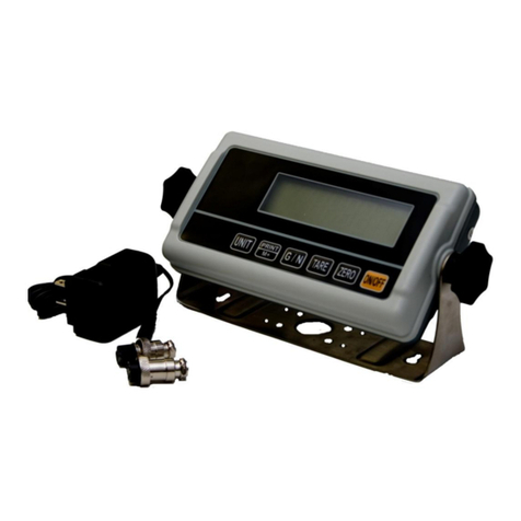
Totalcomp T500E Parts list manual


i
DigitalWeightIndicator
Setup/OperationManual
Revision
1.0
J
uly
8
, 2009

ii
TABLE OF CONTENTS
Page
INTRODUCTION
...........................................................................................................................................................
1
FCC NOTE
....................................................................................................................................................................
1
INSTALLATION
.............................................................................................................................................................
1
PREPARATION
.........................................................................................................................................................
1
CONNECTIONS
........................................................................................................................................................
2
CONNECTING THE WEIGH PLATFORM
.................................................................................................................
2
CONNECTING THE SERIAL I/O DEVICE
................................................................................................................
2
CONNECTING THE POWER SUPPLY
.....................................................................................................................
3
CONFIGURATION
........................................................................................................................................................
3
OVERVIEW
...............................................................................................................................................................
3
ACCESSING THE MENUS
.......................................................................................................................................
3
MENU STRUCTURE
.................................................................................................................................................
3
SETUP MENU DESCRIPTIONS
...............................................................................................................................
5
SETUP MENU PROCEDURES
................................................................................................................................
.7
USER
MENU DESCRIPTIONS
................................................................................................................................
.8
USER MENU PROCEDURES
...................................................................................................................................
9
EXITING THE MENUS
..............................................................................................................................................
9
CALIBRATION
............................................................................................................................................................
10
CALIBRATION OVERVIEW
....................................................................................................................................
10
ZERO CALIBRATION (F16)
....................................................................................................................................
10
SPAN CALIBRATION (F17)
....................................................................................................................................
10
VIEW CALIBRATION VALUES (F18)
......................................................................................................................
11
KEY
-
IN ZERO CALIBRATION VALUE (F19)
..........................................................................................................
12
KEY
-
IN SPAN CALIBRATION VALUE (F20)
...........................................................................................................
12
OPERAT
ION
...............................................................................................................................................................
13
DISPLAY
................................................................................................................................................................
.
13
KEYBOARD
.............................................................................................................................................................
13
FUNCTION KEYS
...............................................................................................................................................
14
GENERAL SCALE OPERATION
.............................................................................................................................
14
WEIGHING AN ITEM
..........................................................................................................................................
14
PIECE COUNTING MODE
..................................................................................................................................
14
PEAK HOLD MODE
............................................................................................................................................
15
REMOTE DISPLAY MODE
................................................................................................................................
.
15
LEGAL FOR TRADE SEALING
...................................................................................................................................
16
APPENDIX A: SPECIFICATIONS
...............................................................................................................................
17
APPENDIX B:
SERIAL PORT INFORMAT
ION
...........................................................................................................
18
SE
RIAL PORT MODES
...........................................................................................................................................
18
DEMAND DUPLEX MODE
..................................................................................................................................
18
CONTINUOUS DUPLEX MODE
.........................................................................................................................
18
AUTO PRINT MODE
...........................................................................................................................................
18
OUTPUT STRINGS
.................................................................................................................................................
19
TEXT PRINT TICKET
..........................................................................................................................................
19
STR
ING FORMAT 1 (Condec Demand String)
...................................................................................................
19
STRING FORMAT 2 (Condec Continuous String)
...............................................................................................
19
APPENDIX C: DISPLAYED ERROR CODES
.............................................................................................................
20
©
Totalcomp
, Inc.
2009
. All rights reserved.
The information contained herein is the property of
Totalcomp
and is supplied without liability for errors or omissions. No part may be
reproduced or used except as authorized by contr
act or other written permission. The cop
y
right and the foregoing restriction on
reproduction and use extend to all media in which the information may be embo
d
ied.
Contents subject to change without notice.
13
-
01 Pollitt Drive Fair Lawn, NJ 07410
Tel (8
00) 631
-
0347 Fax (888) 797
-
2288
http://www.totalcomp.com/

1
INTRODUCTION
The
T500ESS
Digital Indicator is a general purpose, industrial grade weight indicator. One model
is
currently available, distinguishable by display type, enclosure type and power supply. Table 1 shows the
T500ESS
product m
a
trix.
This model can readout up to 50,000 display divisions and can supply enough current for up to 4-
350
load cells. All setup parameters may be entered via the front panel keys, includin
g calibr
a
tion.
If your Model
T500ESS
Digital Indicator is part of a complete floor scale or has
already
been installed for
you, you may skip to
the
operating instructions. Prior to using the indicator, please read this chapter
carefully and completely. Store the manual in a safe and convenient place so it will be available if you
have questions concerning the oper
a
tion of the scale.
MODEL
DISPLAY
TYPE
ENCLOSURE
TYPE
POWER SOURCE
T500ESS
LED
Stainless Steel
100
-
240 VAC, 50/60 Hz 30W
TABLE 1:
T500ESS
S
eries Product Matrix
FCC
NOTE
This equipment has been tested and found to comply with the limits for a Class A digital device, pursuant
to Subpart J of Part 15 of the FCC Rules. These limits are designed to provide reasonable protection
against harmful interference when the equipment is operated in a commercial environment. This
equi
pment generates, uses and can radiate radio frequency energy and, if not installed and used in
accordance with the instructions manual, may cause harmful interference to radio com
munications.
Operation of this equipment in a residential area is likely to cause harmful interference in which case the
user will be required to correct the interference at his/her own e
x
pense.
INSTALLATION
PREPARATION
Any precision instrument re
quires a suitable environment in which to operate as intended. Please review
each of
the following
prior to installation:
Electrical Power
The
T500ESS
indicator has been designed to operate from 100 to 240 VAC at 50/60 Hz. All units ship
with the appropr
iate power plug for its area of intended use.
To avoid electrical noise interference
and/or stray AC electrical transients
, try to operate the indicator
from a circuit
separate
from any equipment containing
inductive devices such as a contactor coil,
so
lenoid, relay coil, or motor
.
Be sure to
use shielded cables for the load cell connections (ground shield
wire at indicator) and run these cables away from
your
AC/DC power cables
if possible
.
In extreme cases, it may be necessary to
install
surge suppre
ssors, line conditioners or even UPS
(
Uninterruptible Power Supplies
)
systems
(not included)
.
Table of contents
Other Totalcomp Measuring Instrument manuals
Popular Measuring Instrument manuals by other brands

Murphy
Murphy PowerView Analog Gages PVA20 installation instructions

Hedue
Hedue HEDU Q2 manual

E+E Elektronik
E+E Elektronik OMNIPORT 30 operating manual

Johnson Matthey
Johnson Matthey Tracerco PED Series user manual
daviteq
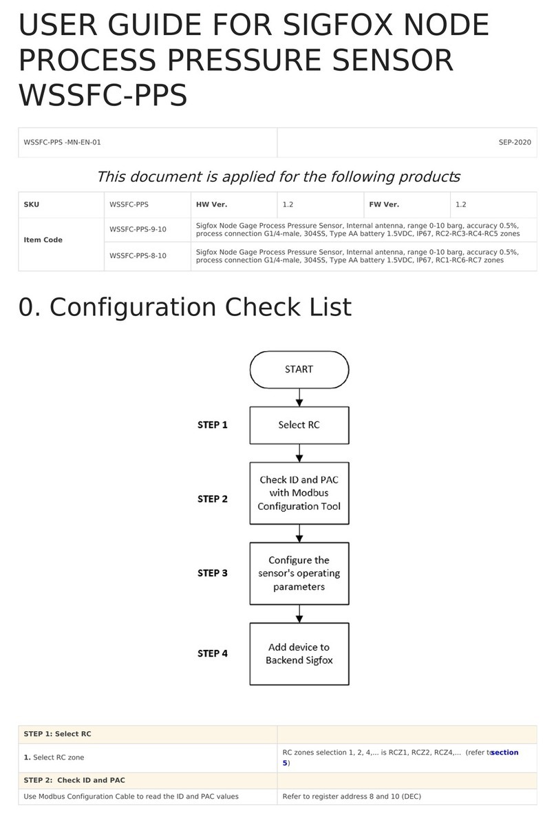
daviteq Sigfox WSSFC-PPS user guide
Delmhorst Instrument Co
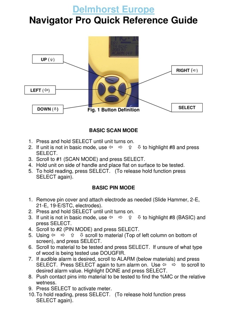
Delmhorst Instrument Co Navigator Pro Quick reference guide
