8
Wiring The Unit
Sultan Acoustic Wave Series
Sultan SMART Units
The Sultan SMART unit has wiring information printed inside the lid of the unit.
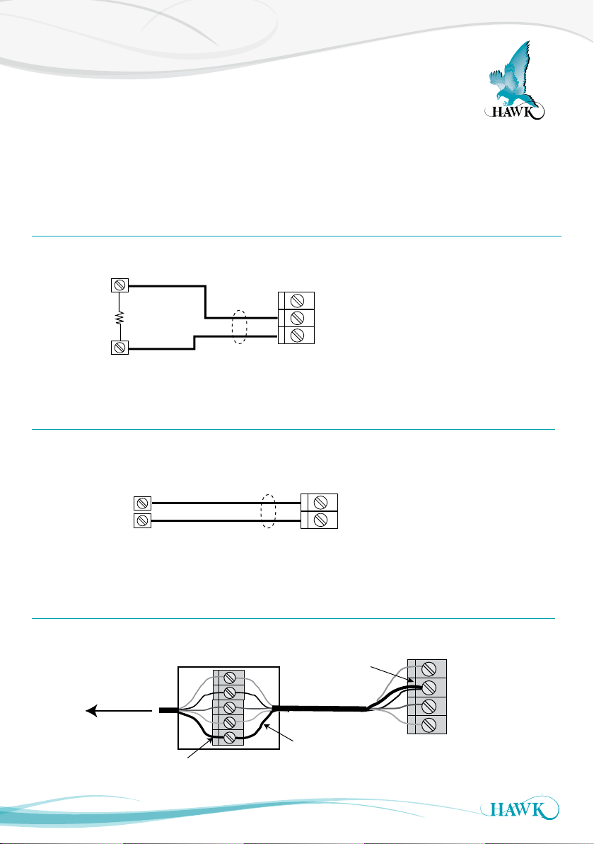
Screw Cap Version
Unscrew the lid to expose the terminals. It is
recommended you remove the terminal block from
the unit before wiring - to do this, insert a screw driver
into one of the middle terminals to lever the block out.
Pass the cables through the cable entry gland before
wiring in to the terminal block.
Ensure the terminal is open by screwing counter
clockwise with a flat head screwdriver. Place the
exposed wires into the open terminals and tighten
until firm. Insert the block back into the unit when
wiring is complete. Press firmly on the plug in terminal
block to ensure it is fully home.
If you are connecting HawkLink communications,
connect the blue wire to B and the white wire to A.
The black wire can be connected to the DC- terminal
next to B.
Tighten cable entry gland(s) and cover to ensure
sealing is effective.
IP68 Sealed Cable Version
Connect the free ends of the cable following the wire
colours as shown in the terminal diagrams.
AWSTD AWSTC
AWSTA
COM
NO
Test in
A
B
-
+
-
+
BWN
ORG
PPL
WT
BLU
BLK
RD
GRN
YEL
RELAY COMMS DC-in 4-20mA
COM
NO
Test in
A
B
-
+
-
+
BWN
ORG
PPL
WT
BLU
BLK
RD
GRN
YEL
RELAY COMMS DC-in 4-20mA
Outputs
- 4-20mA
- Relay
- Modbus Multidrop
Outputs
- Relay
- Modbus Multidrop
Outputs
- 4-20mA
(2) Modbus
RELAY RS - 485
24 Vdc
4-20mA
current sinking
RELAY RS - 485
24 Vdc
(1) (1)
Sinking 4-20mA
from user device
(loop powered)
Notes:
(1) - No internal connection
(2) - Single Modbus connection PC to unit only
Multidrop connection not recommended
For cable only models (without
integrated junction box option),
please use colors shown to
denote wire functions.
For models with integrated
junction box option, remove
plug-in terminal blocks for easier
wiring.
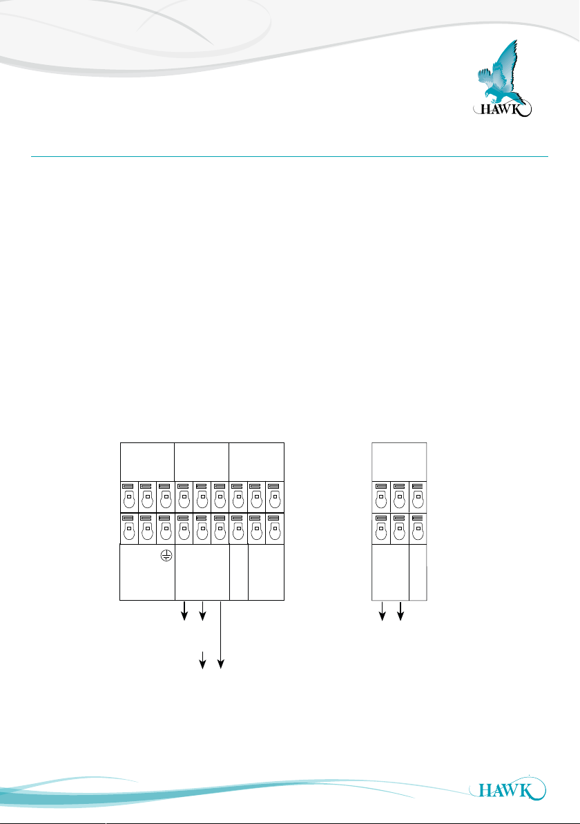
COMMS DC-IN
A
B
12-30VDC
+
RS 485
AC-IN
N
L1
80-265VAC
RELAY 1
NC
COM
NO
RELAY 2
NC
COM
NO
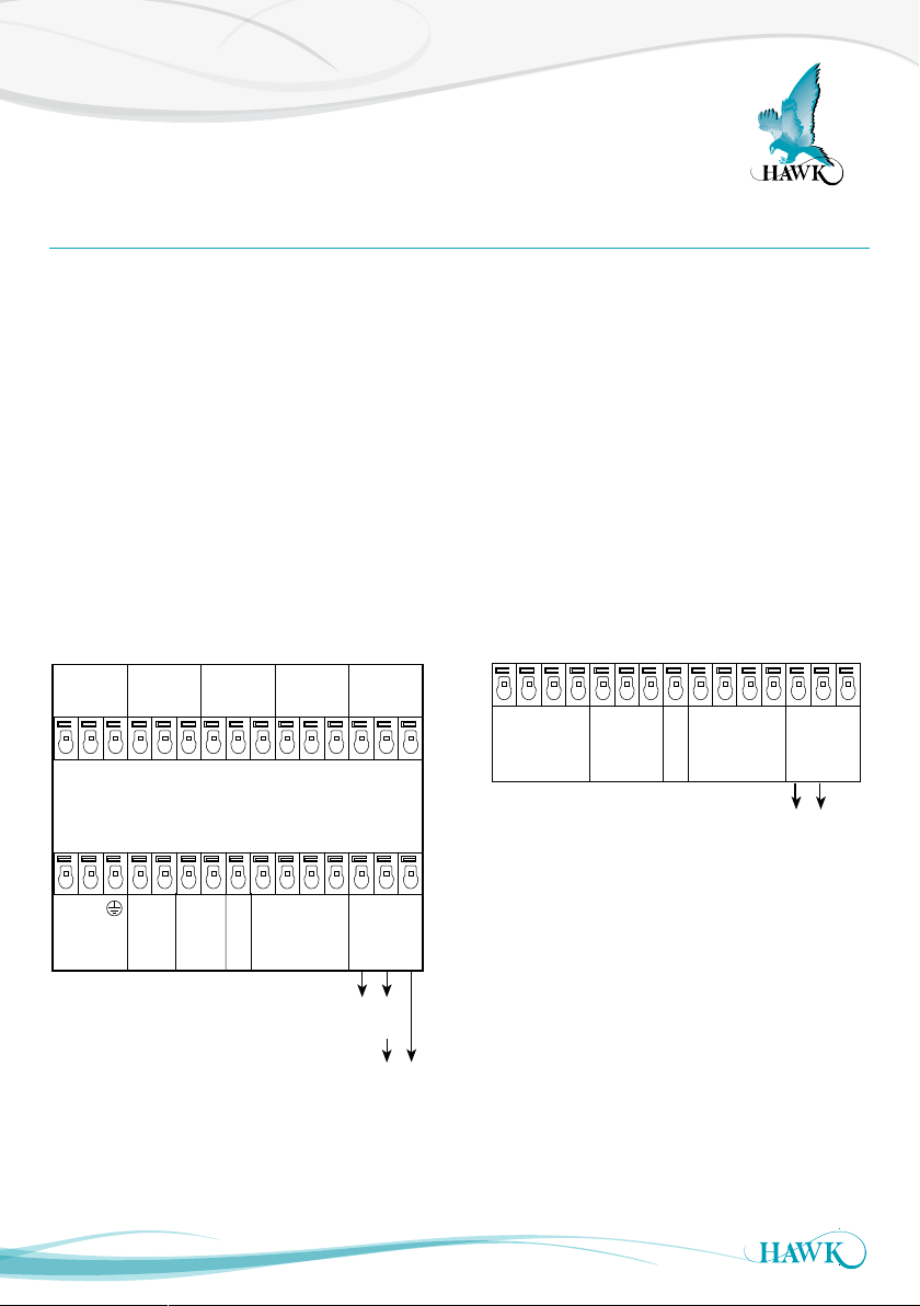
COMMS
A
B
+
–
4-20mA
Is
1L
N
+
–
AC-In
Driving 4-20mA from
Sultan to user PLC
Modulating
4-20mA from
PLC input
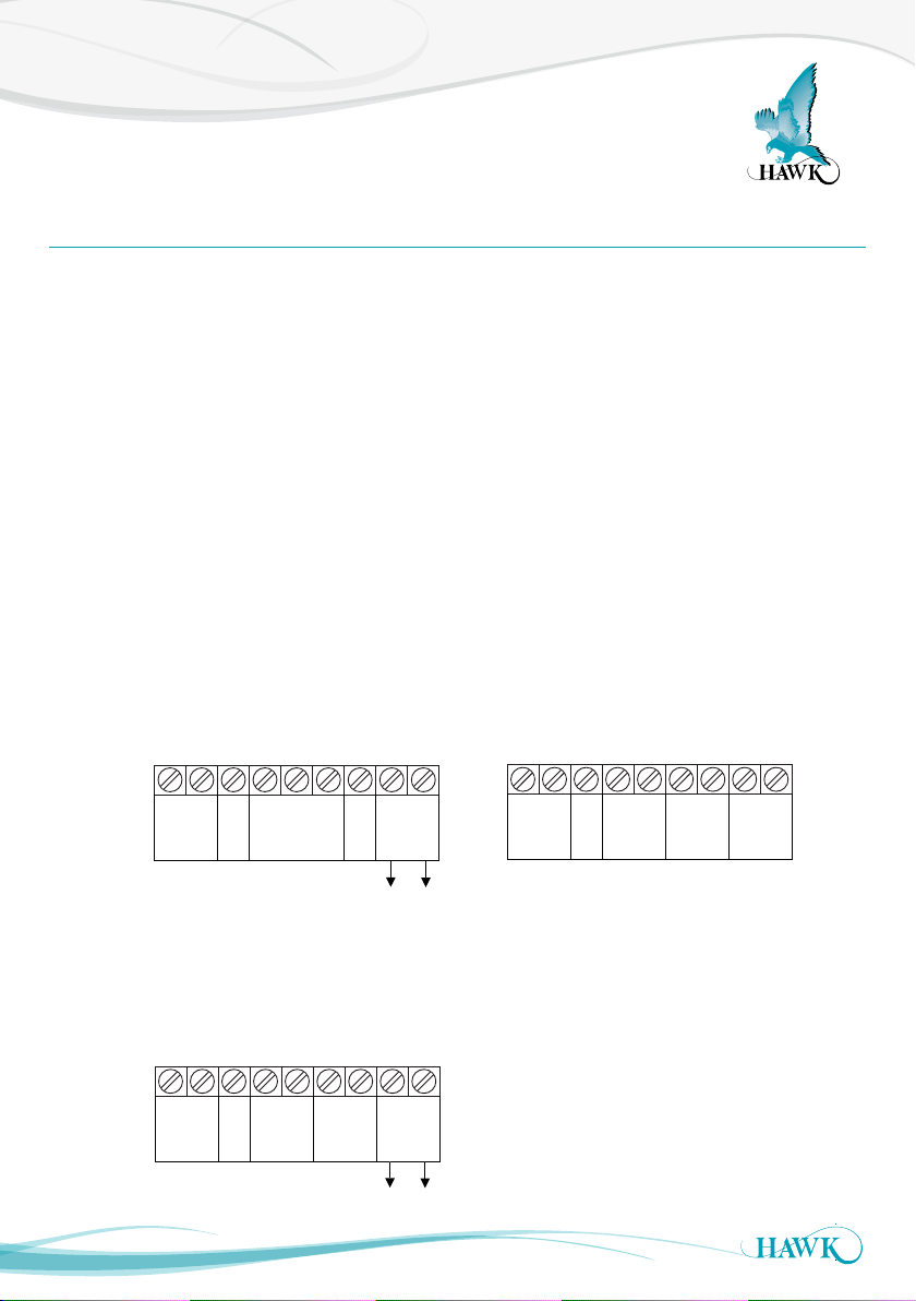
–
Test In
COMMS
A
B
–
Test In
+
COM
N / O
COMMS
A
B
–
Test In
+
COM
N / O
RELAY
Sinking 4-20mA
from user device
+
–
4-20mA
DC in
DC in
PURPLE
WHITE
BLUE
BLACK
GREEN
YELLOW
BROWN
ORANGE
PURPLE
WHITE
BLUE
BLACK
RED
BROWN
ORANGE
PURPLE
WHITE
BLUE
BLACK
RED
GREEN
YELLOW
RELAY
AWSTA version AWSTC version
AWSTD version