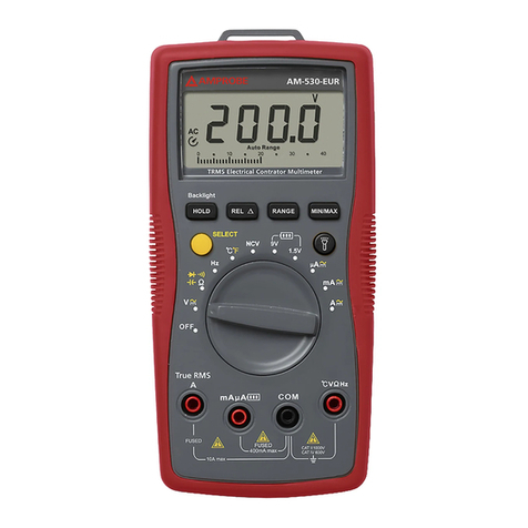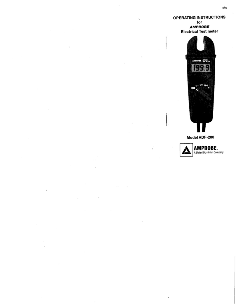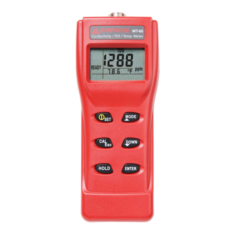
AM-33
3 3/4 DIGITS INTELLIGENT ONESWITCH AUTO DMM
OPERATION MANUAL
SAFETY RULES
λ This meter is designed and tested in accordance with IEC publication 1010, pollution
degree II and installation category (overvoltage category) III 600 .
λ This meter has been tested according to the following EC Directives
♦ 89/336/EEC (EMC of Nov., 1992, Electromagnetic Compatibility)
♦ 73/23/EEC (Product safety law of June 11, 1979, Low oltage Directive of
February 19, 1973)
λ This meter is designed to be indoor use at temperature 41°F to 104°F (5°C to 40°C)
and altitude up to 2,000m.
λ To ensure that the meter is used safely, follow all safety and operating instructions in
this operation manual. If the meter is not used as described in this operation manual,
the safety features of this meter might be impaired.
λ Do not use the meter if the meter or test leads look damaged, or if you suspect that the
meter is not operating properly.
λ When using the probes, keep your fingers behind the finger guards on the probes.
λ Disconnect the live test lead before disconnecting the common test lead.
λ Make sure power is off before cutting, unsoldering, or breaking the circuit. Small
amount of current can be dangerous.
λ Do not apply more than 600 dc or 600 ac rms between a terminal and earth ground.
λ To avoid electrical shock, use CAUTION when working above 60 dc or 25 ac rms.
Such voltages pose a shock hazard.
λ Never make measurements with the battery cover or bottom case off.
λ To avoid electrical shock or damage to the meter, do not exceed the input limits.
INTERNATIONAL SYMBOLS
Important information
see manual Continuity
AC Ground
DC Double insulation
FEATURES
λ One switch operation.
λ Auto polarity with engineering units annunciator.
λ DC volt, AC volt, Resistance
(4 threshold voltage to determine or R function)
λ Continuity test
λ Auto power off with power resume
λ Data hold
λ Full range 600 overload protection
λ Conform to IEC1010-1 CAT III 600
3.1 General Specifications
Display : 3 3/4 digit LCD, 3999 counts with decimal point and
engineering units annunciator display
Polarity : Automatic, (-) negative polarity indication.
Zero adjustment : Automatic.
Measuring Method : Dual slop integration A to D converter system.
Over range indication : Only the “OL” is displayed.
Power : Single, standard 9 volt battery NEDA 1604, JIS 006P,
IEC6F22.
Dimension : 70 (H) x 144 (W) x 40 (D) mm.
Weight : Approx. 270gm. (including batteries and packaging)
3.2 Electrical Specifications
Accuracies are ± (% of reading + number of least significant digits) at 23°C ± 5°C, <75% RH.
DC oltage Range Resolution Accuracy Input
Impedance
4 1m
40 10m ±(0.8%+1) 10MΩResponse time:
400 100m 2 sec. max.
600 1
AC oltage Range Resolution Accuracy Frequency
(Hz) Input Impedance:
4 1m 10MΩ
40 10m 40-400 Response time:
400 100m 2 sec. max.
600 1
±(1.2%+3)
40-100
Resistance Range Resolution Accuracy Open circuit
oltage
400Ω100mΩ±(1.0%+2) _3
Continuity Range Resolution
Test 400Ω100mΩBuzzer sound generation resistance
_47Ω
Overload protection on all range: 600 DC/AC rms <30sec.
PANEL DESCRIPTIONS
1) 3 3/4 digit LCD display
2) Power resume button
3) ON/OFF switch
4) Data hold button
5) Case
6) Input and common terminals
WARNING
OPERATION
1) When measuring voltage ensure that the instrument is not connected. Always ensure that
the correct terminals are used for the type of measurement to be made.
2) Use extreme care when measuring voltage above 50 , especially from sources where
high energy exists.
3) Avoid making connections to “live” circuits whenever possible.
4) When making current measurements ensure that the circuit is not “live” before opening it
in order to connect the test leads.
5) Before making resistance measurements or continuity test, ensure that the circuit under
test is de-energised.
6) Extreme care should be taken when using the instrument to conjunction with a current
transformer connected to the terminals. High voltage may be produced at the terminals if
an open circuit occurs.
7) Ensure that the test leads and prods are in good condition with no damage to the
insulation.
8) Take care not to exceed the over-load limits as given in the specifications.
9) Fuse for replacement must be of the correct type and rating.
5.1 DC and AC oltage measurement
1) Connect the black test lead to the “COM” socket and red test lead to the “ ” socket.
2) Connect the test prods across the source or load under measurement.
5.2 Resistance measurement
1) Connect the black test lead to the “COM” socket and red test lead to the “ ” socket.
2) Connect the prods across the circuit to be tested.
CAUTION: Ensure that the circuit to be tested is “dead”.
Max. input over-load : 600 rms < 30sec.
5.3 Continuity test
1) Connect the black test lead to the “COM” socket and red test lead to the “ ” socket.
2) Connect the prods across the circuit to be tested, if the resistance less than approx. 47Ω,
buzzer will be activated.
5.4 Data hold
A push switch is used to hold data during measurement. Pressing the key, reading is held
and “H” appears on display. Pressing the switch again to release the hold data.
Note : In auto AC/DC voltage selection, if the source under test is AC, hold function will
operative only when source under test is in continuous contact with the test probes.
5.5 Auto power off
The meter will turn off automatically to extend the battery life after approx. 30 minutes without
operation. Resume power by pressing “P. Resume” button.
6. MAINTENANCE
CAUTION
BEFORE ATTEMPTING BATTERY AND FUSE REMO AL OR REPLACEMENT,
DISCONNECT TEST LEADS FROM ANY ENERGISED CIRCUITS TO A OID SHOCK
HAZARD.
6.1 Fitting and replacing the battery
1) Ensure that the instrument is not connected to any external circuit, switch off the meter
and remove the test leads from the terminals.
2) Remove the screw of the back case.
3) Replace the spent battery with the same type.
4) Reinstate the back case, tighten and securing screw.
6.2 Cleaning
Periodically wipe the case with a soft damp cloth and mild household cleanser. Do not use
abrasives or solvents. Ensure that no water gets inside the equipment to prevent possible
shorts and damage.
FOR TECHNICAL ASSISTANCE,
PLEASE CONTACT:
AMPROBE
Tel : 305-423-7500
Fax : 305-423-7554
Technical Support : 800-327-5060
!
!
!


