Totem TM-586 VA User manual

TM-586 VA User’s Manual
1
Introduction
A. Specifications
System Chipset
VIA VT82C580 Apollo VPX chipset.
CPU
One 321-pin socket 7 for Intel
Pentium(P54C/CQS/ CS, P55C), AMD
5k86,K5,K6, Cyrix 6x86 (L,MX), IDT C6
processors, support 75/90/100/110
120/133/150/166/180/200/225/233/266/300MHz
Memory
Expandable to 512MB (2 banks) with two 72-pin
SIMM sockets onboard (Support Fast Page Mode
and EDO DRAM 5-2-2-2) and two 168-pin DIMM
socket (support Syncchronous DRAM module
6-1-1-1).
Cache
64-bit 256/ 512KB L2 Pipeline Burst SRAM
onboard.
I/O
SMC 37C669, two high speed 16550 compatible
serial ports, one Multi-Mode.
Parallel Port support SPP/EPP/ECP standard
mode.
Two onboard PCI IDE Ports (32 bit data transfer).
Support two 360/720KB/1.2/1.44/2.88MB floppy
disk devices.
One PS/2 Mouse port.
BIOS
Award System BIOS installed in socket (Flash
and PnP).
Expansion slots
Three PCI Master Slots and three 16-bit ISA
Slots.
Dimension
4-layer PCB, size (220mm x 190mm).
Others
Support Ultra DMA/33, USB Bus, Keyboard
Power On/Off, ATX Power supply.
TM-586 VA User’s Manual
2
Setup Guide
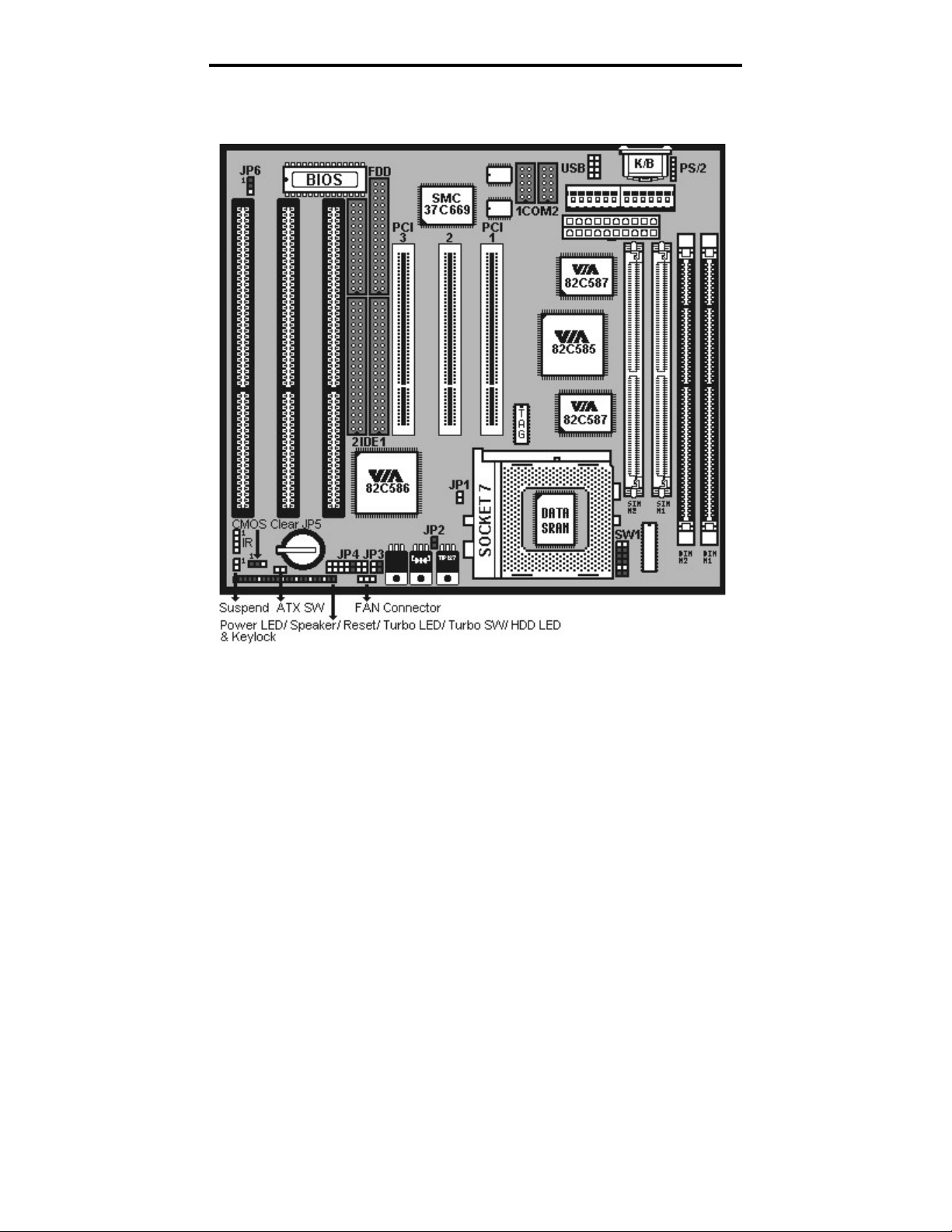
A. Layout Diagram

TM-586 VA User’s Manual
3
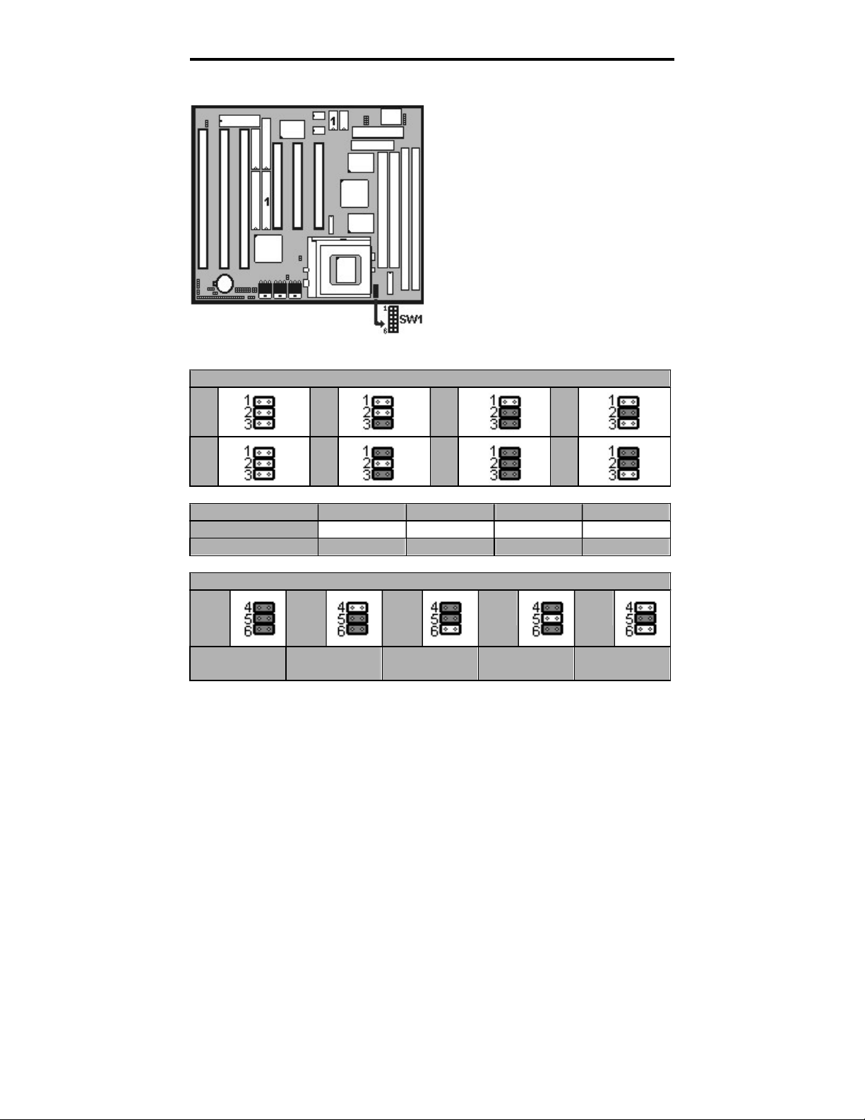
B. Switch Settings for CPUs
On = Short, Off = Open
Intel, AMD, Cyrix
SW1
SW1
1
2
3
RATE
4
5
6
CLK
Pentium 75 MHz
Off
Off
Off
1.5
On
On
On
50
Pentium 90 MHz
Off
Off
Off
1.5
Off
On
On
60
Pentium 100
MHz
Off
Off
Off
1.5
On
Off
On
66
Pentium 120 MHz
Off
Off
On
2
Off
On
On
60
Pentium 133 MHz
Off
Off
On
2
On
Off
On
66
Pentium 150 MHz
Off
On
On
2.5
Off
On
On
60
Pentium (MMX) 166 MHz
Off
On
On
2.5
On
Off
On
66
Pentium (MMX) 200 MHz
Off
On
Off
3
On
Off
On
66
Pentium (MMX) 233 MHz
Off
Off
Off
3.5
On
Off
On
66
Pentium (MMX) 266 MHz
On
Off
On
4
On
Off
On
66
AMD
-
5k86
-
P75
-
75MHz
Off
Off
Off
1.5
On
On
On
50
AMD
-
5k86
-
P90
-
90MHz
Off
Off
Off
1.5
Off
On
On
60
AMD
-
K5
-
75MHz
-
PR75
Off
Off
Off
1.5
On
On
On
50
AMD
-
K5
-
90MHz
-
PR90
Off
Off
Off
1.5
Off
On
On
60
AMD
-
K5
-
100MHz
-
PR100
Off
Off
Off
1.5
On
Off
On
66
AMD
-
K5
-
90MHz
-
PR120
Off
Off
Off
1.5
Off
On
On
60
AMD
-
K5
-
100MHz
-
PR133
Off
Off
Off
1.5
On
Off
On
66
AMD
-
K5
-
133MHz
-
PR166
Off
On
On
1.75
On
Off
On
66
AMD
-
K6(MMX)
-
1
66MHz
Off
On
On
2.5
On
Off
On
66
AMD
-
K6(MMX)
-
200MHz
Off
On
Off
3
On
Off
On
66
AMD
-
K6(MMX)
-
233MHz
Off
Off
Off
3.5
On
Off
On
66
AMD
-
K6(MMX)
-
266MHz
On
Off
On
4
On
Off
On
66
AMD
-
K6(MMX)
-
300MHz
On
On
On
4.5
On
Off
On
66
Cyrix 6x86
-
100MHz
-
P120+
Off
Off
On
2
On
On
On
50
Cyrix 6x86
-
110MHz
-
P133+
Off
Off
On
2
Off
On
On
55
Cyrix 6x86
-
120MHz
-
P150+
Off
Off
On
2
Off
On
On
60
Cyrix 6x86
-
133MHz
-
P166+
Off
Off
On
2
On
Off
On
66
Cyrix 6x86
-
150MHz
-
P200+
Off
Off
On
2
Off
On
Off
75
Cyrix MII
-
PR166
Off
On
On
2.5
Off
O
n
On
60
Cyrix MII
-
PR200
Off
On
On
2.5
On
Off
On
66
Cyrix MII
-
PR233
Off
On
On
2.5
Off
On
Off
75
Cyrix MII
-
PR266
Off
On
Off
3
On
Off
On
66
Cyrix MII
-
PR300
Off
Off
Off
3.5
On
Off
On
66

TM-586 VA User’s Manual
4
C. CPU Voltage Settings
JP4 = Single voltage CPU (Intel P54C, Cyri
x 6x86, AMD 5k86/K5)
JP1
JP2
3.52V
3.38V
On
Off
In Dual voltage CPU, you only need to set up Vcore. Just “Open” JP1
and “Short” JP2, VI/O will supply 3.3V automatically.
Remember to make sure CPU voltage set up is 100% correct by
referring to Page 11 and Page 12. Any voltage error setup happened in
Dual Voltage CPU will cause system unstable or doesn’t work, or even
worse is that it will burn out your CPU.
JP4 = Dual voltage CPU(Intel P55C, Cryrix 6x86L, MX
-
6x86, AMD
-
K6)
JP1
JP2
Vcore
3.20V
Vcore
2.90V
Vcore
2.80V
Off
On
Vcore
2.20V
VI/O default setting : 3.30V
Vcore default setting : 2.80V
JP1=Open, JP2=Short.
Switch voltage is applied,
making the temperature lower
and voltage steadier.
All the voltage specifications
adopted here are the averages
of the working voltage
suggested by t
he CPU makers,
to make any CPU applied work
with the best performance.
In Single voltage CPU
VI/O=Vcore.
TM-586 VA User’s Manual
5
D. CPU Frequencies
SW1(1/2/3)
= Multipliper Factor for
Intel / AMD / Cyrix CPU
1.5
2 2.5
3
3.5
4
4.5
5
Intel P54C/P55C
X1.5/X3.5
X2
X2.5
X3
Cyrix 6x86(L)/MX
None/
X3.5
X2
X2.5
X3
A
MD
-
5k86/K5/K6
X1.5/X3.5
None
X1.75/X2.5
X3
SW1(4/5/6)
= CPU
Ex. Clock
Select
50
MHz
55
MHz
60
MHz
66
MHz
75
MHz
PCI Bus Clk
25MHz
PCI Bus Clk
27MHz
PCI Bus Clk
30 MHz
PCI Bus Clk
33 MHz
PCI Bus Clk
37 MHz
The CPU type default setting is
Intel Pentium 166MHz=66 MHz
*2.5.
When a CPU with 75MHz is
applied, the PCI Bus CLK output
becomes 37MHz. Under this
circumstance, some VGA cards
may not fit well. Then the
system becomes unsteady,
tends to hang up easily or even
results in boot failure. Use
another VGA card instead when
any of the above-mentioned
conditions happens.
TM-586 VA User’s Manual
6
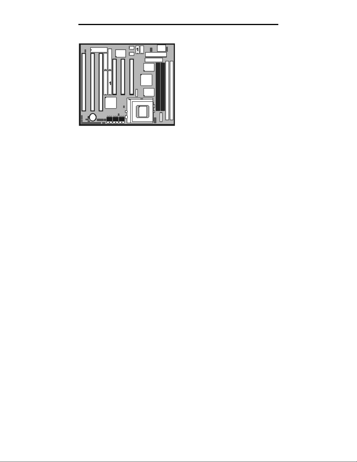
E. DRAM, EDO RAM Installation Procedures:
Change nothing if EDO RAM is used. BIOS automatically detects the
RAM type.
With 586 CPUs, two FPM/EDO RAM Modules are required on SIMM
sockets to compose a bank for the system to start.
In VIA VPX chipset, SIMM and DIMM RAM are able to co-work.
MEMO for Installing Syatem:
⊕ Concerning memory setup, you can find how to from “Chipset
Frature Setup” under BIOS setup. However, to avoid system unstable
or system hang, user without engineering background is not suggested
to change BIOS set up.
⊕ If system boot failure, please clean SIMM socket (with clean oil) or
polish Gold-Finger of DRAM with soft eraser, and try again.
SIMM Socket output voltage is
5V, expandable to 512MB.
Support 5V Fast Page Mode/
Extended Data Out RAM.
The BIOS DRAM default setting
is 70 ns. Change the BIOS
“Chipset Feature Setup” default
setting to 60ns for better
performance, if the chipset is
marked 60ns.
TM-586 VA User’s Manual
7
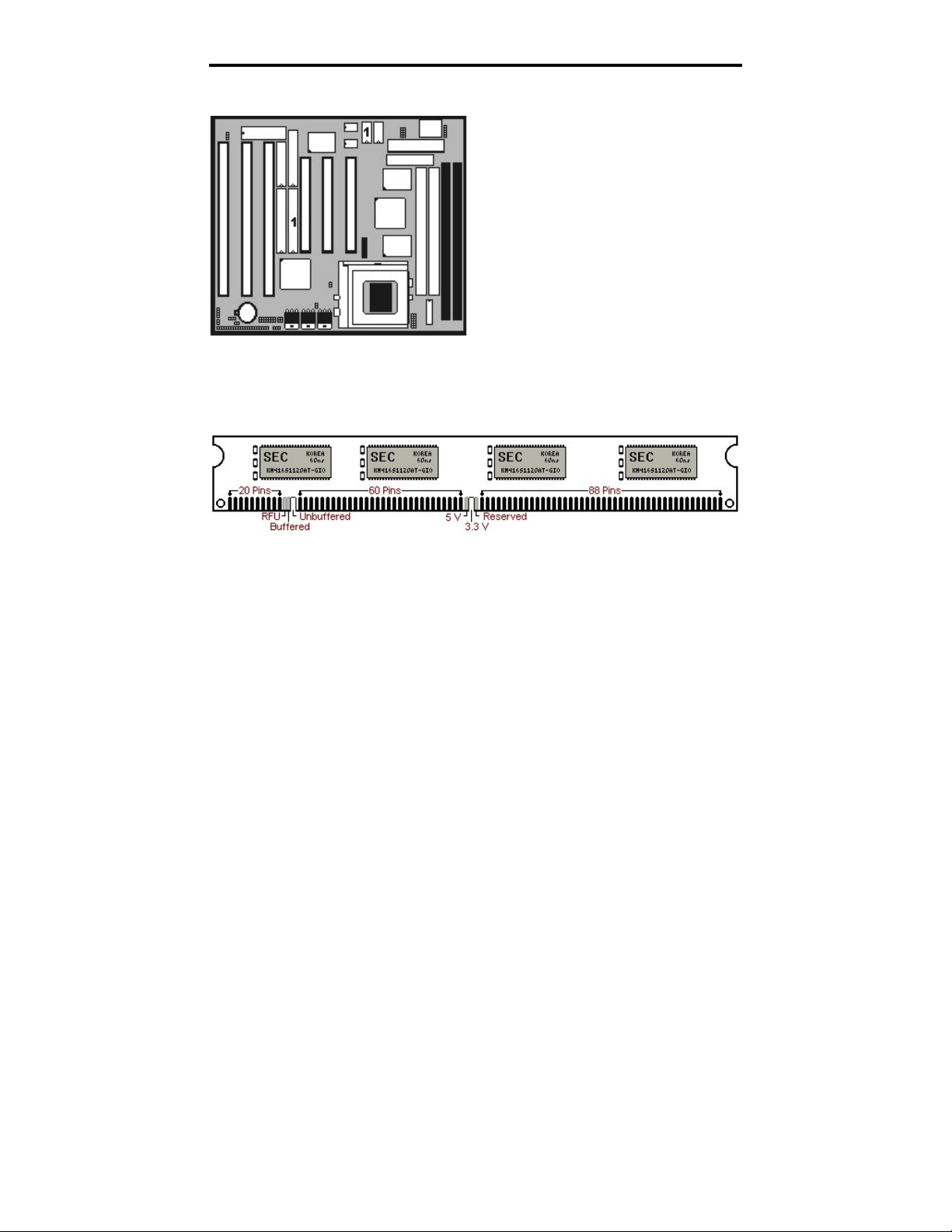
F. SDRAM, Cache Memory Installation Procedures:
The Dual Inline Memory Module (DIMM) must be 3.3 Volt and
Unbuffered Synchronus DRAM (SDRAM) 8MB, 16MB, 32MB or 64MB.
The following illustration shows the type of DIMM Module.
168-PIN SDRAM DIMM Notch Key Definitions
Default setting: 3.3V.(Only)
First, verify the working voltage of
the EDO/SDRAM module in either
DIMM socket (DIMM1 or
DIMM2-table free).
You can set up the BIOS “Chipset
Feature Setup” to the best working
condition basing on the type of
EDO/SDRAM you are using.

TM-586 VA User’s Manual
8
G. Other Jumper Settings
POWER SW (FOR ATX POWER SUPPLY):
The button should be a momentary switch that is normally open.
Pushing the ATX Power Switch will immediately change the system
status. Before or during “POST”, you need to hold the button for four
seconds in order to turn off the system.
JP5: Clear CMOS
Turn off the system and short pins 2-3 (J3) to clear CMOS. Then short
pins 1-2 before turning it on. You may damage the chipset if you power
on the system by shorting pins 2-3.
JP5
1-2 Normal operation(Default).
2-3
for clearing CMOS Data.
CPU Cooler Fan connector
This is the connector for CPU cooler. Never use the jumper to short the
connector. Serious damages caused this way will not be warrantied.
Power LED & Keylock:
Keyboard lock switch and
Power LED connector.
Speaker:
Connect to the system’s
speaker for beeping.
Reset:
Short to restart system.
HDD LED:
LED ON when on board PCI
IDE hard disk activates.
SMI SW:
Short to enter sleep mode. A
keystroke or mouse movement
(mouse driver exits) will instantly
“wake up” the system.
Table of contents
Other Totem Motherboard manuals


