ST EVALSP1340CPU User manual

September 2012 Doc ID 022878 Rev 3 1/35
UM1522
User manual
EVALSP1340CPU evaluation board, revision 2.2
1 Introduction
This document applies to revision 2.2 evaluation boards.
This evaluation board is intended to be used to:
●enable quick evaluate and debugging of software for the SPEAr1340 embedded MPU
●act as a learning tool for rapid familiarity with the features of the SPEAr1340
●provide a reference design to use as a starting point for the development of a final
application board
The EVALSP1340CPU board is equipped with interfaces to the high-speed peripherals
embedded in SPEAr1340 device.
Figure 1. EVALSP1340CPU board rev. 2.2
www.st.com

Contents UM1522
2/35 Doc ID 022878 Rev 3
Contents
1 Introduction . . . . . . . . . . . . . . . . . . . . . . . . . . . . . . . . . . . . . . . . . . . . . . . . 1
2 Kit contents . . . . . . . . . . . . . . . . . . . . . . . . . . . . . . . . . . . . . . . . . . . . . . . . 6
3 Features and block diagram . . . . . . . . . . . . . . . . . . . . . . . . . . . . . . . . . . . 7
3.1 Board features . . . . . . . . . . . . . . . . . . . . . . . . . . . . . . . . . . . . . . . . . . . . . . 7
3.2 Implemented SPEAr1340 device features . . . . . . . . . . . . . . . . . . . . . . . . . 9
3.3 Plugboards . . . . . . . . . . . . . . . . . . . . . . . . . . . . . . . . . . . . . . . . . . . . . . . . 10
3.4 Connectors, jumpers and pushbuttons . . . . . . . . . . . . . . . . . . . . . . . . . . . 11
4 Getting started . . . . . . . . . . . . . . . . . . . . . . . . . . . . . . . . . . . . . . . . . . . . . 12
4.1 Connecting . . . . . . . . . . . . . . . . . . . . . . . . . . . . . . . . . . . . . . . . . . . . . . . . 12
4.2 Booting . . . . . . . . . . . . . . . . . . . . . . . . . . . . . . . . . . . . . . . . . . . . . . . . . . . 12
4.3 Serial interface . . . . . . . . . . . . . . . . . . . . . . . . . . . . . . . . . . . . . . . . . . . . . 13
4.4 Reset switch . . . . . . . . . . . . . . . . . . . . . . . . . . . . . . . . . . . . . . . . . . . . . . . 13
5 Block descriptions . . . . . . . . . . . . . . . . . . . . . . . . . . . . . . . . . . . . . . . . . 14
5.1 General power supply . . . . . . . . . . . . . . . . . . . . . . . . . . . . . . . . . . . . . . . 14
5.1.1 Power LEDs . . . . . . . . . . . . . . . . . . . . . . . . . . . . . . . . . . . . . . . . . . . . . . 15
5.2 Dynamic memory subsystem . . . . . . . . . . . . . . . . . . . . . . . . . . . . . . . . . . 15
5.2.1 Up to 2 GByte of DDR3 @533 MHz . . . . . . . . . . . . . . . . . . . . . . . . . . . 15
5.3 Static memory subsystem . . . . . . . . . . . . . . . . . . . . . . . . . . . . . . . . . . . . 16
5.3.1 Serial Flash . . . . . . . . . . . . . . . . . . . . . . . . . . . . . . . . . . . . . . . . . . . . . . 16
5.3.2 NAND Flash . . . . . . . . . . . . . . . . . . . . . . . . . . . . . . . . . . . . . . . . . . . . . . 16
5.3.3 NAND Flash expansion . . . . . . . . . . . . . . . . . . . . . . . . . . . . . . . . . . . . . 16
5.4 PCIe/SATA . . . . . . . . . . . . . . . . . . . . . . . . . . . . . . . . . . . . . . . . . . . . . . . . 17
5.4.1 PCIe clock . . . . . . . . . . . . . . . . . . . . . . . . . . . . . . . . . . . . . . . . . . . . . . . 17
5.5 Ethernet subsystem . . . . . . . . . . . . . . . . . . . . . . . . . . . . . . . . . . . . . . . . . 18
5.5.1 Ethernet LEDs . . . . . . . . . . . . . . . . . . . . . . . . . . . . . . . . . . . . . . . . . . . . 18
6 USB 2.0 subsystem . . . . . . . . . . . . . . . . . . . . . . . . . . . . . . . . . . . . . . . . . 19
6.1 Host ports . . . . . . . . . . . . . . . . . . . . . . . . . . . . . . . . . . . . . . . . . . . . . . . . . 19
6.2 Host LEDs . . . . . . . . . . . . . . . . . . . . . . . . . . . . . . . . . . . . . . . . . . . . . . . . 19

UM1522 Contents
Doc ID 022878 Rev 3 3/35
6.3 OTG USB . . . . . . . . . . . . . . . . . . . . . . . . . . . . . . . . . . . . . . . . . . . . . . . . . 19
7 A/D Interface . . . . . . . . . . . . . . . . . . . . . . . . . . . . . . . . . . . . . . . . . . . . . . 20
8 RTC (battery connector) . . . . . . . . . . . . . . . . . . . . . . . . . . . . . . . . . . . . . 20
9 I²S audio bus . . . . . . . . . . . . . . . . . . . . . . . . . . . . . . . . . . . . . . . . . . . . . . 20
10 Memory SD card interface . . . . . . . . . . . . . . . . . . . . . . . . . . . . . . . . . . . 21
11 MEMS . . . . . . . . . . . . . . . . . . . . . . . . . . . . . . . . . . . . . . . . . . . . . . . . . . . . 21
12 LCD panel and touch screen function . . . . . . . . . . . . . . . . . . . . . . . . . . 21
13 Debug interface . . . . . . . . . . . . . . . . . . . . . . . . . . . . . . . . . . . . . . . . . . . . 22
14 Strapping options . . . . . . . . . . . . . . . . . . . . . . . . . . . . . . . . . . . . . . . . . . 23
15 Test modes . . . . . . . . . . . . . . . . . . . . . . . . . . . . . . . . . . . . . . . . . . . . . . . . 24
16 LEDs . . . . . . . . . . . . . . . . . . . . . . . . . . . . . . . . . . . . . . . . . . . . . . . . . . . . . 25
17 Jumper descriptions . . . . . . . . . . . . . . . . . . . . . . . . . . . . . . . . . . . . . . . . 26
18 Connectors . . . . . . . . . . . . . . . . . . . . . . . . . . . . . . . . . . . . . . . . . . . . . . . 27
19 Pushbuttons . . . . . . . . . . . . . . . . . . . . . . . . . . . . . . . . . . . . . . . . . . . . . . 28
Appendix A Licence agreements . . . . . . . . . . . . . . . . . . . . . . . . . . . . . . . . . . . . . 29
Revision history . . . . . . . . . . . . . . . . . . . . . . . . . . . . . . . . . . . . . . . . . . . . . . . . . . . . 34

List of tables UM1522
4/35 Doc ID 022878 Rev 3
List of tables
Table 1. Summary of SPEAr1340 device features on the main board and plugboards . . . . . . . . . . . 9
Table 2. Common power rails. . . . . . . . . . . . . . . . . . . . . . . . . . . . . . . . . . . . . . . . . . . . . . . . . . . . . . 14
Table 3. Power LEDs . . . . . . . . . . . . . . . . . . . . . . . . . . . . . . . . . . . . . . . . . . . . . . . . . . . . . . . . . . . . 15
Table 4. PCIe clock settings (default settings) . . . . . . . . . . . . . . . . . . . . . . . . . . . . . . . . . . . . . . . . . 17
Table 5. Ethernet LEDs . . . . . . . . . . . . . . . . . . . . . . . . . . . . . . . . . . . . . . . . . . . . . . . . . . . . . . . . . . 18
Table 6. USB host LEDs. . . . . . . . . . . . . . . . . . . . . . . . . . . . . . . . . . . . . . . . . . . . . . . . . . . . . . . . . . 19
Table 7. OTG micro USB-AB LEDs . . . . . . . . . . . . . . . . . . . . . . . . . . . . . . . . . . . . . . . . . . . . . . . . . 19
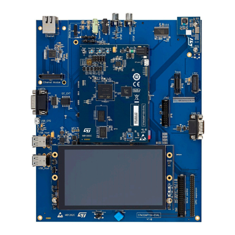
Table 8. J4 ADC connector ADC (optional) . . . . . . . . . . . . . . . . . . . . . . . . . . . . . . . . . . . . . . . . . . . 20
Table 9. J29 JTAG connector pin-out . . . . . . . . . . . . . . . . . . . . . . . . . . . . . . . . . . . . . . . . . . . . . . . . 22
Table 10. SW1 SPI Slave selection . . . . . . . . . . . . . . . . . . . . . . . . . . . . . . . . . . . . . . . . . . . . . . . . . . 23
Table 11. SW2 Voltage interface setting . . . . . . . . . . . . . . . . . . . . . . . . . . . . . . . . . . . . . . . . . . . . . . 23
Table 12. SW3 software boot options (default settings) . . . . . . . . . . . . . . . . . . . . . . . . . . . . . . . . . . . 23
Table 13. Test modes (default settings) . . . . . . . . . . . . . . . . . . . . . . . . . . . . . . . . . . . . . . . . . . . . . . . 24
Table 14. Status LEDs . . . . . . . . . . . . . . . . . . . . . . . . . . . . . . . . . . . . . . . . . . . . . . . . . . . . . . . . . . . . 25
Table 15. List of board jumpers . . . . . . . . . . . . . . . . . . . . . . . . . . . . . . . . . . . . . . . . . . . . . . . . . . . . . 26
Table 16. List of board connectors . . . . . . . . . . . . . . . . . . . . . . . . . . . . . . . . . . . . . . . . . . . . . . . . . . . 27
Table 17. Document revision history . . . . . . . . . . . . . . . . . . . . . . . . . . . . . . . . . . . . . . . . . . . . . . . . . 34

UM1522 List of figures
Doc ID 022878 Rev 3 5/35
List of figures
Figure 1. EVALSP1340CPU board rev. 2.2 . . . . . . . . . . . . . . . . . . . . . . . . . . . . . . . . . . . . . . . . . . . . . 1
Figure 2. Block diagram . . . . . . . . . . . . . . . . . . . . . . . . . . . . . . . . . . . . . . . . . . . . . . . . . . . . . . . . . . . . 8
Figure 3. Connector locations (top) . . . . . . . . . . . . . . . . . . . . . . . . . . . . . . . . . . . . . . . . . . . . . . . . . . 11
Figure 4. Primary serial cable setting (J34) . . . . . . . . . . . . . . . . . . . . . . . . . . . . . . . . . . . . . . . . . . . . 13
Figure 5. Secondary serial cable setting (optional connector J35) . . . . . . . . . . . . . . . . . . . . . . . . . . 13
Figure 6. Serial Flash M25P64 (U11) and M25P40 (U12) enable . . . . . . . . . . . . . . . . . . . . . . . . . . . 16
Figure 7. NAND Flash selection. . . . . . . . . . . . . . . . . . . . . . . . . . . . . . . . . . . . . . . . . . . . . . . . . . . . . 16
Figure 8. NAND Flash device voltage selector . . . . . . . . . . . . . . . . . . . . . . . . . . . . . . . . . . . . . . . . . 16
Figure 9. SPEAr NAND8/16 Flash I/O voltage selector . . . . . . . . . . . . . . . . . . . . . . . . . . . . . . . . . . . 17
Figure 10. SPEAr MIPHY PLL power selectors . . . . . . . . . . . . . . . . . . . . . . . . . . . . . . . . . . . . . . . . . . 17
Figure 11. SPEAr GMII I/F voltage selector. . . . . . . . . . . . . . . . . . . . . . . . . . . . . . . . . . . . . . . . . . . . . 18

Kit contents UM1522
6/35 Doc ID 022878 Rev 3
2 Kit contents
●EVALSP1340CPU main board
●CLCD VGA plugboard
●AC power adapter (output voltage 12V 2A)

UM1522 Features and block diagram
Doc ID 022878 Rev 3 7/35
3 Features and block diagram
3.1 Board features
●SPEAr1340 embedded MPU
●4 DDR3 chips (32-bit) 1 GB
●Serial NOR Flash, 8 MB
●8-bit NAND Flash, 2 Gb
●16-bit NAND Flash expansion connector
●Audio stereo jack and microphone
●Two USB 2.0 high speed host ports
●One OTG 2.0 high speed port (Micro USB-AB)
●One 10/100/1000 Ethernet port
●One PCIe X1 Root Complex connector
●One SATA connector
●One SDIO connector
●One UART serial port (up to 115 Kbaud)
●LCD connectors (LVDS bus - TFT panel)
●MEMS (accelerometer & magnetometer)
●Debug port (CPU JTAG connector)
●Camera module (1600x1200)
Optional
●10" LCD kit - order code EVALSP1340LCD
●CLCD Video HDMI transmitter plugboard - order code EVALSP1340HDM

Features and block diagram UM1522
8/35 Doc ID 022878 Rev 3
Figure 2. Block diagram
Bank 1
Bank 2
Bank 3
Bank 0
DDR bus
LVDS
transmitter
24 bit FPD
PHY RGMII
SD card
connector
Memory
card
plugboard
connector
LCD
plugboard
connector
VS6624
camera
module
connector
SATA
PCIe
NAND
2Gb
FSMC bus
SD bus
USB_UHC1
USB_UHC0
USB_UOC
UART 1
UART 2
MIPHY
MEMS
gyroscope
MEMS
accelerometer
magnetometer
STM25P64
STM25P40
cs_0
INT Mag
INT Acc
INT Gyro
Audio
interface
Stereo jack
Microphone
jack
I2S
I2C
CLCD
VIP/CAM
RJ45
SMI bus
SPI bus
Up to 2 Gbytes
SPEAr1340

UM1522 Features and block diagram
Doc ID 022878 Rev 3 9/35
3.2 Implemented SPEAr1340 device features
The following table shows the device features, the primary and alternate functions as well as
the specific plugboard used.
All IPs except Timer and MHY_debug are testable.
The XGPIO pins listed in the table can be set through software registers.
Legend:
X = available
= not available
Table 1. Summary of SPEAr1340 device features on the main board and plugboards
Feature Mainboard Dedicated
pin/XGPIO
Shared
function
Availableon
plugboard
DDR3 SDRAM X X
2 x USB Host
(USB_UHC0+USB_UHC1) XX
USB OTG controller (USB_UOC) X X
PCIe/SATA
(PCIe+SATA+MiPHY) XX
SMI X XGPIO
SPI (SSP) X XGPIO No
SPI (SSP_SS3n) X XGPIO No (1)
2 x I2C
(I2C0+I2C1) X XGPIO No
2 x UART(TX /RX only) (UART0+UART1) X XGPIO No
UART0 X XGPIO Timer (2)
GMAC
(GMAC+GMII) XGPIO No
2 x CEC
(CEC0+CEC1) XGPIO No(1) CLCD
CLCD X(3) XGPIO ARM ETM CLCD
MCIF (SD/MMC) X XGPIO No
FSMC (NAND Flash) X XGPIO No
FSMC (NAND x16) X (4) XGPIO Keyboard
FSMC (NOR) X (4) XGPIO MCIF
PWM1 XGPIO SSP_SS1n
PWM2 Wake_up XGPIO Keyboard
PWM3 DDR_SHUT_OFF XGPIO Timer (2)
PWM4 DDR _SHUT_OFF XGPIO Timer (2)

Features and block diagram UM1522
10/35 Doc ID 022878 Rev 3
3.3 Plugboards
Plugboards allow you to adapt the evaluation board to interface with different hardware
interfaces. They are connected to the main board through small high speed shielded
connectors to avoid quality degradation of the signals. Each plugboard has the interface
connectors in different positions to prevent insertion errors. Two video output plugboards are
available: CLCD_VGA (included in the EVALSP1340CPU box) and CLCD_HDMI
(EVALSP1340HDM can be ordered separately).
The CLCD plugboards support all the standards supported by the SPEAr1340 CLCD IP.
Each plugboard contains a physical video chip interface, video connector, local power
supply, and it implements all routing rules for standard requests.
●CLCD Video HDMI transmitter plugboard
– A/V transmitter: Analog Device AD9889B
– Supports HDMIv1.3 up to 1080p and UXGA@60Hz
– Bandwidth: 165 MHz
– HDCP v1.2 protocol
– Supports both S/PDIF and I2S audio
– Order code EVALSP1340HDM
●CLCD VGA plugboard
– Analog Devices AD7125
– 303 msps throughput rate
– Triple 8-bit DAC
The VGA plugboard or the HDMI plugboard must be plugged into connectors J7 and J8.
1. Shared with MPHY_debug
2. Timer not testable. Pins used for DDR_SHUT_OFF
3. Some CLCD pins are shared with MPHY_debug
4. Only strip connector on board

UM1522 Features and block diagram
Doc ID 022878 Rev 3 11/35
3.4 Connectors, jumpers and pushbuttons
Figure 3. Connector locations (top)
DB
!
"
!
#
#!
!
!
!
$%
!
#
!
#
#
!
!
!
!
&
'
&
&
!
!
#
&
(!
(
"
!#
&
)
!
&
&
&
&
&
$%
$%!
#
(
&
!
*+
(#
&
&
#
,
,!
,
,
!
(
#
#
!
#
!
#
#
#
#
#
#
&
"!
(
#!
#
,
#
&
#
(
,
&
&
&
&#
#
&
#
#
#!
!
$%#
#
#
#
# &
!
!
#
!
!#
&
"
'
#
#
#
&
&
&
&!
!
#
!
#
!
"
&
'
#!
!
)#
!
!
!
#
&
!
#
##
&
&
!
!
#
,
,#
, ,#
!
,
,
,
,
&
&
)
&
)
!
#
&
&#
#
#
#
##
&
!
#
(
(!
(
-
(
(#
!
!
#
$%
,
! !
!
!
!
!
!
#
&
#
!
$%
&
&
'
#
&#
!
-!
!!
-
!#
&# & & (
#
& &
! &
-
& !
,
&
! (
!
!
'!
,
!#
#
-
&!
!
!
&!
&
!
&#
! ,
!! &
&
&
,
&
&

Getting started UM1522
12/35 Doc ID 022878 Rev 3
4 Getting started
Caution: This board contains electrostatic-sensitive devices
The EVALSP1340CPU board is shipped in protective anti-static packaging. Do not submit
the board to high electrostatic potentials, and follow good practices for working with static
sensitive devices.
●Wear an anti-static wristband. Wearing a simple anti-static wristband can help to
prevent ESD from damaging the board.
●Zero potential. Always touch a grounded conducting material before handling the
board, and periodically while handling it.
●Use an anti-static mat. When configuring the board, place it on an anti-static mat to
reduce the possibility of ESD damage.
●Handle only the edges. Handle the board by its edges only, and avoid touching board
components.
4.1 Connecting
1. Connect a serial cable adapter (RS232 on J34) to a host PC (see Primary Serial cable
setting).
2. On a host PC running Windows or Linux, start the Terminal program.
3. Connect the AC adapter to a power outlet.
4. Power on the board (plug the AC adapter jack into SW6). A sequence of boot
messages displays, followed by the Linux console prompt.
4.2 Booting
The EVALSP1340CPU board can boot a Linux kernel pre-installed in the serial NOR Flash.
At power on, the serial port outputs a brief header message with some uBoot information
(uBoot version, SDK version, and some internal hardware information). At this point, you
can choose to:
●Stop the system directly in uBoot
To do this, press the spacebar on the host computer keyboard before the boot delay
time expires (default is 3 seconds).
●Boot Linux
The system logs you in automatically as super user, and the Linux shell prompt
displays on the screen.

UM1522 Getting started
Doc ID 022878 Rev 3 13/35
4.3 Serial interface
A serial interface, which can typically be used to connect an operating system monitor
console, is available on the J34 (primary, null modem connection). A secondary serial
inference is available on J35 (optional).
●J34 is marked UART1 on the board and is connected to UART0 on the SPEAr1340
device
●J35 is marked UART2 on the board is connected to UART1 on the SPEAr1340 device
It is possible to simulate a cross cable by changing the position of the JP28 jumpers as
shown below.
Refer to the schematic drawing (contact your local ST representative for availability), for the
pin-out of the connectors.
Figure 4. Primary serial cable setting (J34)
Figure 5. Secondary serial cable setting (optional connector J35)
4.4 Reset switch
A manual reset switch (P2) is available on the top side of the board.
Cross
cable
JP28
12
34
JP28
12
34
modem
cable
Null
Cross
cable
JP26
12
34
JP26
12
34
modem
cable
Null

Block descriptions UM1522
14/35 Doc ID 022878 Rev 3
5 Block descriptions
5.1 General power supply
The power supply block generates all the required voltages from a 12 V or a 5 V external
AC/DC (plugged in J30). The generated voltages are:
●5 V generated from 12 V with a step-down switching regulator (if 12 V ext. AC/DC is
used)
●5 V obtained from an over voltage protection device with thermal shutdown (if 5 V ext.
AC/DC is used)
●1.2 V, 1.5 V, 2.5 V, and 3.3 V generated from 5 V with a step-down switching regulator
●1.8 V generated from 3.3 V with a low drop voltage regulator
●Up to 18.7 V generated from 12 V with a Step-up switching regulator (for LCD back
light, default 12 V)
Table 2. Common power rails
Name Use
Jumper
for current
measurement
+12V or +5V J30: Power input connector
VDD1V2 SPEAr core (SPEAr_VDD1V2)
SPEAr DDR3 interface (SPEAr_DDR3_1V2)
JP30
JP35
VDD1V5
DDR3 chips
SPEAr DDR I/O (SPEAr_DDR3_1V5)
SPEAr RTC (RTC_VDD1V5)
JP36
JP27
VDD1V8
SPEAr 1.8 V NAND8 Flash (JP20: Close 2&3 for 1.8V)
SPEAr 1.8 V NAND16 Flash (JP37: Close 2&3 for 1.8V)
Audio chip STA529 (U18)
VDD2V5
Spear_VDD2V5:
SPEAr_OTP antifuses (mounted R292 to supply)
SPEAr GMII interface(JP4: Close 2-3 for 2.5V)
MIPHY_VDD2V5_PLL
SPEAr ADC_PLLs_VDD2V5 (JP17)
SPEAr USB_VDD2V5 (JP18)
A2D connector (J4)
JP31
VDD2V8 Camera Module (J42)

UM1522 Block descriptions
Doc ID 022878 Rev 3 15/35
5.1.1 Power LEDs
5.2 Dynamic memory subsystem
5.2.1 Up to 2 GByte of DDR3 @533 MHz
Four 78-ball FPGA, x8 data interface components are present as follows:
●4x 4 Gbit = 2 GByte (Micron MT41J512M8)
VDD3V3
SPEAr (SPEAr_VDD3V3)
SPEAr GMII interface (JP4: Close 1-2 for 3.3 V)
Audio chip STA529 (U18)
PCIe Clock source
PCIe Voltage
JTAG MIPHY connector
NAND Flash
NAND8 Flash chip (Close 1&2 of JP20 for 3.3 V)
NAND16 Flash chip (Close1&2 of JP37 for 3.3 V)
CPU JTAG & trace connectors
JP32
+12V_HOST PCIe x1 connectors
LCD_BL Back light voltage up to 18.7 V
Table 2. Common power rails (continued)
Name Use
Jumper
for current
measurement
Table 3. Power LEDs
Ref. Des. Description
D16&D18 green 5 volt: +5V
D17 green 1.2 volt: VDD1V2
D20 green 1.5 volt: VDD1V5
D22 green 1.8 volt: VDD1V8
D21green 2.5 volt: VDD2V5
D19 green 3.3 volt: VDD3V3

Block descriptions UM1522
16/35 Doc ID 022878 Rev 3
5.3 Static memory subsystem
5.3.1 Serial Flash
The following components are connected to the SMI interface:
●M25P64 (U11) ST serial Flash device: memory size = 8 MB
●M25P40 (U12) ST serial Flash device: memory size = 512 KB (optional, the device is
not installed on the board)
To enable M25P64 or M25P40, use SMI_CS0 with the JP12 jumpers set as shown in
Figure 6.
Figure 6. Serial Flash M25P64 (U11) and M25P40 (U12) enable
5.3.2 NAND Flash
This block is based on Micron NAND Flash MT29F16G08 (U47) (2 GB: bus width = x8). If
required, this chip can be replaced and another can be used. To do this, deselect the on-
board Flash by removing jumper JP19, and connect an adapter board to J21, J22.
Figure 7. NAND Flash selection
5.3.3 NAND Flash expansion
Two 50-pin expansion connectors (J21, J22) enable the use of different Flash devices.
When used, remove jumper JP19.
On the expansion connectors it is possible, through JP20, to select NAND_VDD between
3.3 V and 1.8 V to test different voltage devices. The NAND FLASH SPEAr I/O voltage has
to be aligned with the Flash device voltage. Use JP20 and Strapping option SW2.1 & SW2.2
to set the correct voltage.
Figure 8. NAND Flash device voltage selector
JP12
12
34
JP12
12
34
SMI_CS0n
U12 enableU12 enable
SMI_CS0n
JP19
12 U47
deselected
JP19
12 U47
selected
Closed Open
JP20
133.3 V
2
JP20
13
21.8 V

UM1522 Block descriptions
Doc ID 022878 Rev 3 17/35
Figure 9. SPEAr NAND8/16 Flash I/O voltage selector
5.4 PCIe/SATA
One standard x1 PCIe connector (J24) and one standard SATA connector (J25 plus J41 for
Hdd Sata Power) are present on the board.
A single MPHY is shared through serial resistors.
If R470, R472, R474 and R476 (0 Ohm) are installed and R469, R471, R473, R475 are not
installed the PCIe is available. Otherwise, if R143 (0 Ohm) R245 (200 Ohm) are installed
and R456, R457, R257, R258 are not loaded, the SATA is available.
Note: SATA configuration is the default.
Figure 10. SPEAr MIPHY PLL power selectors
5.4.1 PCIe clock
The PCIe clock is generated by U23 ICS557-03 (differential clock generator). This device
can generate 4 different clock frequencies. This depends on the settings of bits SS1, SS0,
S1 and S0.
JP20
133.3 V
2
JP20
131.8 V
2
NAND8
JP37
133.3 V
2
JP37
131.8 V
2
NAND16
JP22
12
2.5 V
(default
JP21
12
3.3 V
(default
open)
closed)
Table 4. PCIe clock settings (default settings)
SS1 (SW4-4) SS0 (SW4-3) S1(SW4-2) S0 (SW4-1) Spread % Spread type Output frequency
0 0 0 0 No spread Not applicable 25
0 0 0 1 No spread Not applicable 100
0 0 1 0 No spread Not applicable 125
0 0 1 1 No spread Not applicable 200
0 1 0 0 -0.5 Down 25
0 1 0 1 -0.5 Down 100
0 1 1 0 -0.5 Down 125
0 1 1 1 -0.5 Down 200
1000-0.75Down 25

Block descriptions UM1522
18/35 Doc ID 022878 Rev 3
The output frequency must be set at 100 MHz. On the EVALS1340CPU board the default
settings is: S1= 0, all others =1.
5.5 Ethernet subsystem
One RGMII chip PHY Micrel KSZ9031/9021RN (U9) is present on board, plus a transformer
and Ethernet RJ45 connectors (J2).
The factory settings for the strapping options are fixed to support Ethernet speed 1000 with
auto-negotiation, ID.
SPEAr GMII I/F VDD can be 3.3 V or 2.5 V. It is possible test this functionality by changing
the position of jumper JP4 as shown below:
Figure 11. SPEAr GMII I/F voltage selector
5.5.1 Ethernet LEDs
1001-0.75Down 100
1010-0.75Down 125
1011-0.75Down 200
1 1 0 0 No spread Not applicable 25
(1) (1) (0) (1) No spread Not applicable 100
1 1 1 0 No spread Not applicable 125
1 1 1 1 No spread Not applicable 200
Table 4. PCIe clock settings (default settings) (continued)
SS1 (SW4-4) SS0 (SW4-3) S1(SW4-2) S0 (SW4-1) Spread % Spread type Output frequency
JP4
133.3 V
2
JP4
132.5 V
2
Table 5. Ethernet LEDs
Reference Description
LED1 (yellow)
(on J2)
DUPLEX STATUS: The LED is lit when the PHY is in full duplex operation after
the link is established.
LED2 (green)
(on J2)
GOOD LINK LED: The LED output indicates that the PHY has established a
good link.

UM1522 USB 2.0 subsystem
Doc ID 022878 Rev 3 19/35
6 USB 2.0 subsystem
6.1 Host ports
The board has two host ports that are fully compliant with the USB 2.0 specification (two
controllers with one port each). This means that the two hosts can work in concurrent mode
with the maximum possible bandwidth. Each host also has full control of the VBUS supplied
by the TPS2052 power switch that also provides over current protection in case of a short
circuit in the USB cable. The ports are equipped with LEDs showing the power status of
each port (the green LED indicates the presence of VBUS and the red one the current
limiter status).
6.2 Host LEDs
6.3 OTG USB
One OTG micro USB-AB connector is present on the board.
Table 6. USB host LEDs
Reference Description
D5 Red USB HOST1 OVERCURRENT: Abnormal current flowing on USB host 1 port
D6 Green USB HOST1 VBUS: VBUS present on USB host port 1
D8 Green USB HOST2 VBUS: VBUS present on USB host port 2
D10 Red USB HOST2 OVERCURRENT: Abnormal current flowing on USB host 2 port
Table 7. OTG micro USB-AB LEDs
Reference Description
D7 Red USB OTG OVERCURRENT: Abnormal current flowing on OTG USB
D9 Green USB OTG VBUS: VBUS present on OTG USB

A/D Interface UM1522
20/35 Doc ID 022878 Rev 3
7 A/D Interface
Eight analog input lines are provided on the J4 strip connector.
The connector also allows you to determine the conversion range by setting the conversion
limits on pins J4.18 (lower limit) and J4.4 (upper limit). The default setting is to have pins 1-2
and 19-20 shorted by jumpers, which sets the conversion range to the maximum value of 0
to 2.5 V, with a granularity of 2.44 mV.
Removing the two jumpers and providing different values on pins 2 and 20 makes it possible
to reduce the range, increasing the granularity. For example, an input of 1 V on J4.20 and
2 V on J4.4 provides a range of 1 to 2 V, in steps of less than 1 mV.
In any case, ensure the following relationships between the pins:
8 RTC (battery connector)
To avoid losing data even if the main power supply is switched off, the Real Time Clock can
be powered with a 3 V external battery (BH1).
9 I²S audio bus
The bidirectional I²S bus drives the STM STA529 digital stereo audio amplifier. A 3.5 mm
audio stereo jack (J39) and a 3.5 mm microphone jack (J40) are available on the board.
Audio stereo channels are also available on Jumpers J12 & J14 (optional). A microphone
input is available on jumper J16 (optional).
Table 8. J4 ADC connector ADC (optional)
Pin number Signal
1 ADC_VDD2V5
2 ADC_VREFP
4 ... 18 (even only) AIN0 ... AIN7
3 ... 19 (odd only) AGND
20 ADC_VREFN
0 V ≤J4.20 ≤J4 18 .. 43 ≤J4-2 ≤+2.5 V
AGND ≤Vref_n ≤ADC_In channels ≤Vref_p ≤AVDD
Table of contents
Other ST Motherboard manuals

ST
ST STEVAL-ISB044V1 User manual

ST
ST STM32L5 Nucleo-144 board User manual

ST
ST UM1682 User manual

ST
ST SPC582B-DIS User manual

ST
ST ST25RU3993 User manual

ST
ST STEVAL-SPIN3202 User manual

ST
ST STM32U5 User manual

ST
ST STM3240G-EVAL User manual

ST
ST SPC572LADPT80S User manual

ST
ST SPC58NHADPT386S User manual

ST
ST STM3220G-EVAL User manual

ST
ST MB1367 User manual

ST
ST STM32H7B3I-EVAL User manual

ST
ST STM3210C-EVAL User manual

ST
ST STM32H747I-DISCO User manual

ST
ST STEVAL-SMARTAG2 User manual

ST
ST eMotion STEVAL-MKI109V1 User manual

ST
ST STUSB03E User manual

ST
ST SPC582B-DIS User manual

ST
ST STM32303C-EVAL User manual