manuals.online logo
Brands
  1. Home
  2. •
  3. Brands
  4. •
  5. Toto
  6. •
  7. Kitchen & Bath Fixture
  8. •
  9. Toto DLE127BSK Instructions for use

Toto DLE127BSK Instructions for use

0G494X 2016.08
Construction manual
Automatic faucet
To fully take advantage of this product, please correctly install it according to this
manual.
After installation, please introduce using methods to customers in detail.
This product is supplied with Operation manual (Guarantee). If you have any problem
in use, please call the national after-sale service hotline of Toto (China) Co., Ltd. at
8008209787 or 4008209787 (for mobile phones) free of charge.
Safety instructions (Please follow them for safety reasons)
For safety reasons, please carefully read the safety instructions and install the product correctly.
●To ensure this product is installed correctly and avoid injuries or property damage to
customers or others, this manual lists many symbols.
These symbols and their meanings are listed as follows.
Symbol Meaning
WARNING
Ignoring this symbol and operating incorrectly
may cause death or serious injuries.
CAUTION
Ignoring this symbol and operating incorrectly
may cause injuries and property damage.
Symbol Meaning Symbol Meaning
Prohibited Mandatory
Prohibited
Do not use power supplies of other than AC 220V.
Or it may cause fire and electric shocks.
WARNING
WARNING
Prohibited
Do not use loose sockets.
Or it may cause fire and electric shocks.
Do not pour water onto the power plug or the functional part.
Or it may cause fire and electric shocks.
Do not perform harsh actions for the power cable (bend, put
heavy objects, etc.).
Or it may cause fire.
The actual power mustn’t exceed the rated power of the
socket or traversing unit.
If octopus traversing mode, etc. is used, causing the actual
power exceeding the rated power, overheating may cause fire.
The water supply temperature should not exceed 85°C.
Or it may shorten the service life of the product, damage the
product, cause scalding or cause property damage due to water
leakage.
No touching
Do not touch angle valves and pipes for water supply at the
hot water supply side directly.
Or it may cause scalding.
Do not plug or unplug the power plug with wet hands.
Or it may cause electric shocks.
Do not touch the power plug when lightening occurs.
Or it may cause electric shocks.
Do not use
it in damp
places
Do not install it in damp places such as bathrooms.
Or it may cause faults or electric shocks.
Do not
disassemble
Do not disassemble, repair or modify the product.
Or it may cause fire or electric shocks.
Appearance
Model No. DLE127BSK DLE127BE
Type Dry cell Alternating current
Supply voltage Dry cells (2 AA cells) AC 220V 50/60Hz
Consumed
power
Standby 0.2mW 0.4W
Operating - 0.6W
Water supply
pressure
Minimum water
pressure 0.05MPa
Maximum water
pressure 1.0MPa
Water type Tap water or potable well water
Hot water supply temperature 60 ~ 85°C
Operating ambient temperature 1 ~ 55°C
Sensing distance 180mm
(sensing distance is set automatically according to the installed wash basin)
Length of wire - 850mm
2.2kg 2.5kg
3.2kg 3.5kg
Length of conductors for sensor 0.85m~1.6m
Outflow rate 2L/min
Specification of thread
connection for water supply G 1/2
Water efficiency Grade 1
Net weight
Gross weight
Packaging dimension
(Length*Width*Height) 440mm×305mm×125mm
Safe service life 10 years
Applications For washrooms of public areas and conventional residential housing
1
3 4
2
WARNING
Mandatory
When you unplug the power plug, please grasp the plug to
unplug it.
If you pull and drag the power cable, the power plug or the power
cable may be damaged, causing fire or electric shocks.
Please plug the power plug into place.
Or it may cause fire and electric shocks.
Please assign qualified professionals to install this product.
Disabled persons, mentally challenged persons and persons
who lack common sense (including children) should use this
product under the supervision of a special person.
CAUTION
Prohibited
Do not exert strong force or impacts.
Or damage to the internal parts may cause injuries or faults and
water leakage.
Do not install this product outdoors or in places where icing
may occur.
Or family property may be soaked due to damage of this product
and water leakage, resulting in property damage.
Mandatory
The cold water supply pressure must be higher than or
equal to the hot water supply pressure to ensure normal use
of this product.
Or the temperature cannot be adjusted normally.
When cleaning the filtering screen, please close the angle
valves for water supply (2 places) and make sure the part of
the filtering screen at the hot water supply side won’t burn
your hands.
Or hot water spilled out may cause scalding or family property may
be soaked due to water leakage, resulting in property damage.
Apply silica gel to the power plug to avoid any water
entering it.
■
■
■
Before installation, please wash out dirt, sand, etc., in the water supply pipe thoroughly.
Connect the joint for the check valve with the ltering screen
Remove the filtering screen from the
joint for the check valve and put it into
the angle valve for water supply.
Screw the joint for the check valve
into the angle valve for water supply.
Joint for check
valve
Filtering screen
Angle valve for
water supply
Fix the faucet temporarily
Insert the faucet into the installation
hole of the earthenware.
Orient the faucet towards the water
outlet, and screw the hexagon nut
to fix the faucet temporarily.
Please try not to entangle the water supply
pipe with the connecting line of the sensor.
Faucet location
Drainage hole Faucet part
Center of basin
Hexagon nut
Installation steps
Make sure the
indicator light of the
sensor is illuminated
Water supply temperature:
60°C~85°C
Remove the cover of
the functional part
Install the functional
part
Install the cover of the
functional part
Fix the faucet temporarily
Fix the faucet
Cold water Hot water
Insert the connecting line of the
sensor
Clean the water supply pipe
Connect the joint for the
check valve with the filtering
screen
Insert the power
plug (AC type)
Clean the water supply pipe
Temperature
adjusting handle
Important
Before installation
1. Check the water supply pressure
z The water supply pressure is from 0.05 to 1.0MPa. Please use it within this pressure range.
z When the water supply pressure exceeds 1.0MPa, please use the reducing valve to reduce the
pressure to 0.2MPa.
We suggest you use the water pressure of about 0.2MPa, which is more comfortable during use.
z The cold water supply pressure must be higher than or equal to the hot water supply pressure.
2. Check the hot water supply temperature
z To avoid scalding due to mis-operation, the hot water supply temperature should not exceed 85°C.
3. For layout of pipes and lines
z Too long hot water pipes from the water heater may cause heat loss. Please calculate the shortest
distance to install the hot water pipes and wrap them with thermal insulation materials.
4. Others
z Please try not to damage the surface of the sensor.
z Aqua-auto is only used indoors. Please do not install it outdoors.
z Converters or other machines using infrared rays may cause misoperation.
z Because this product is checked for water inlet before packaging, there may be water in this
product, and it is not a problem.
z When it is necessary to use drainage components, angle valves for water supply, components to
install reversed hooks, brackets, frames, etc., matching the earthenware installed, please confirm
related construction materials and purchase them separately.
Standard installation drawing
Outlet 385 ~ 405
Inlet 350
DLE124BSK DLE124BE
Product view
Faucet
Sensor
Connecting line
Functional
part
Water
supply hose
Hexagon nut
Temperature
adjusting handle
Faucet
Sensor
Connecting line
Functional
part
Water
supply hose
Hexagon nut
Temperature
adjusting handle
Accessories
Alkaline dry cells
(2 AA cells)
(* for DLE127BSK)
Hex wrench Knob switch Operation manual Construction
manual
Product model and specication
Do not install the filtering screen
inversely.
Caution
Connect the water supply
pipe with the joint for the
check valve
Caution
5
7 8
6
Hot water
supply hose
Screw the hexagon nut tightly, and fix the faucet
part on the earthenware.
* To screw the hexagon nut, please use the
following tools.
x Socket wrench (size 13mm)
x T-wrench (size 13mm)
x Adjustable wrench (size 13mm)
Connect the joint for the check valve with the water supply pipe
Connect the water supply pipe with the joint for
the check valve.
y Please avoid the washer from falling
down.
Angle valve for
water supply
Joint for check valve
Washer
Water supply
pipe
Caution
Remove the cover of the functional part
Remove the cover of the functional part in the
direction shown in the figure.
Cover of functional part
(Dry cell type)
Cover of functional part
(Alternating current type)
Drill 2 holes in the wall as shown
in the figure.
Install the functional part onto the
wall as shown in the figure.
Unit: mm
Insert the connecting line of the sensor
Insert the connector as shown in the figure until it clicks.
(Dry cell type)
(Alternating current type)
Connector for sensor
Insert the power plug (AC type)
Insert the power plug into the power socket.
When the power supply is connected, the
sensing distance is set automatically and
immediately, please do not cover the sensor with
your hands or put any object in the earthenware.
(it takes about 20 seconds)
Make sure the indicator light of the sensor is illuminated
When the sensor is not covered by hands and there is no
object in the earthenware, please make sure the indicator
light of the sensor of the faucet does not flash.
* If the indicator light of the sensor still flashes,
please adjust the direction of the faucet slightly until
the indicator light does not flash.
* The indicator light automatically stops flashing about
10 minutes after the power supply is connected. If
you have not finished adjustment to the faucet before
the indicator light automatically stops flashing, please
unplug the connector for the sensor, and insert it
again.
y When checking the indicator light of the sensor,
please orient the sensor towards the spherical
center of the earthenware.
y Depending on types of earthenware, the
indicator light of the sensor will not stop flashing
sometimes. In this case, please set the product
normally. (the indicator light will stop flashing
about 10 minutes later)
Sensor
Power plug
Caution
Caution
Fix the faucet
Hexagon nut
Install the cover of the functional part
After you make sure the connector is
connected, please close the cover of the
functional part and fix it with screws.
(Dry cell type)
Cover of functional part
(Alternating current type)
y Please close cover of functional part tightly.
y Please make sure the functional part is installed
in correct direction.
y When you close the cover of the functional part,
please check whether the connecting line is
caught.
Caution
9
11 12
10
Install the functional part
Important
Check for water leakage
Please refer to “Connect the joint for
the check valve with the filtering screen”
1. Test-run
After installation, please perform test-run as follows.
y Check whether there is water leakage
Please open the angle valves for hot water supply and cold water supply (2 places) to check whether
there is water leakage.
y When your hands approach the faucet, water flows from the faucet.
y About 1~2 seconds after your hands leave the faucet, the faucet stops supplying water.
y After the faucet supplies water for about 1 minute, the water stops automatically. (The sensing mode of
the sensor is intelligent. If the object to be sensed holds still for 15 seconds, the faucet automatically stops
supplying water.)
y When the sensor senses an object with strong reflection placed 4 cm in front of the faucet, such as a
switch, the faucet can supply water for up to 1 minute.
* If there is water in the basin, the sensor may sense incorrectly due to water.
* If the sensor cannot run normally, please follow the steps from “ Insert the connecting line of
the sensor” in “ Installation steps” to check it again.
After installation
2. Clean the ltering screen
For AC type faucets, please cut off the power
supply firstly.
If the filter screen is clogged, water flow is
reduced, and the faucet cannot function fully.
1. Close the angle valves for hot water supply and
cold water supply (2 places).
* Please make sure the hot water supply
side won’t burn your hands.
Caution
y Please avoid the washer from falling
down.
2. Unscrew the water supply hoses and the joints for
the check valve to take out the ltering screen. (for
hot water supply and cold water supply (2 places))
3. Use a tool such as a soft brush to clean the lter-
ing screen.
4. Put the ltering screen back.
5. Open the angle valves for hot water supply and
cold water supply (2 places).
After installation, please check whether
there is water leakage.
Water supply
hose
Angle valve for
water supply
Filtering
screen
Joint for check
valve
Washer
Angle valve for
water supply
Close
Filtering
screen
Soft
brush
Turn the temperature adjusting handle to
adjust the water temperature.
If you want to increase temperature, please turn
upwards; or turn downwards to decrease temperature.
The temperature is adjusted to 38°C at delivery. To
produce hot water at this temperature, the hot water
supply temperature must be higher than 60°C.
* The water temperature varies depending on the
water supply pressure or temperature. Please adjust
if necessary.
WARNING
Mandatory
You must tell the customer that the temperature
adjusting screw is removed and submit temperature
adjusting screw to the customer.
Or it may cause scalding.
Prohibited
The water supply temperature should not exceed
85°C.
Or it may shorten the service life of the product, damage
the product, cause scalding or cause property damage due
to water leakage. To avoid scalds due to mis-operation, the
recommended water supply temperature is 60°C.
Caution
Cold water
Hot water
y Please avoid the wires contacting the angle valves for water supply at the hot water supply side.
The wires may age due to high temperature of the hot water supply side.
y When the hot water supply temperature or pressure is low, the set temperature may not be
reached even if you have turned the temperature adjusting handle to the hot water side fully.
Adjust the water temperature to the maximum
When the temperature adjusting handle is turned to the hot water side fully
and the water supply temperature is undesirable, you can adjust the water
temperature to the maximum. (for details, please see pages 9 ~10 in the operation manual.)
1. Close the angle valves for hot water supply and
cold water supply (2 places).
2. Use the knob switch to unscrew the bubble former
on the faucet.
3. Use a tool such as a soft brush to clean.
4. Use the knob switch to put the bubble former
back.
5. Open the angle valves for hot water supply and
cold water supply (2 places).
After installation of the bubble former,
please check whether there is water
leakage from the faucet.
Soft brush
4. Clean the faucet
For AC type faucets, please cut off the
power supply firstly.
Close
Angle valve for
water supply
Bubble former
Knob switch
Bubble
former
View upon completion
After installation, please check the following items.
Angle valve for
water supply
Faucet
Sensor
connecting
line
Cold water Hot water
Bubble
former
Check for water ow
When the water flow is low, please
check the following items.
Is the angle valve for water
supply opened?
Please open the angle valve
for water supply
Is the filtering screen clogged
by dirt?
Reference
4. Clean the
faucet
Check for loose parts
Please check whether there are loose
parts.
Is the faucet loose?
Please refer to
“Fix the faucet”
2. Clean the
ltering screen
Check the connector
Please check whether there is water leakage.
Is there water leakage from the joint for the check valve
and the filtering screen?
Are the joint for the check valve and the water supply
pipe connected firmly?
Please refer to “Connect the joint for
the check valve with the water supply pipe”
Please check whether the connector is inserted firmly.
Is the connector inserted firmly?
Is the faucet clogged by dirt?
Reference
3. Adjust water temperature properly
13
15
14
Temperature
adjusting handle
16
Important
Please refer to “Insert the connecting
line of the sensor”
Faucet

This manual suits for next models

1

Other Toto Kitchen & Bath Fixture manuals

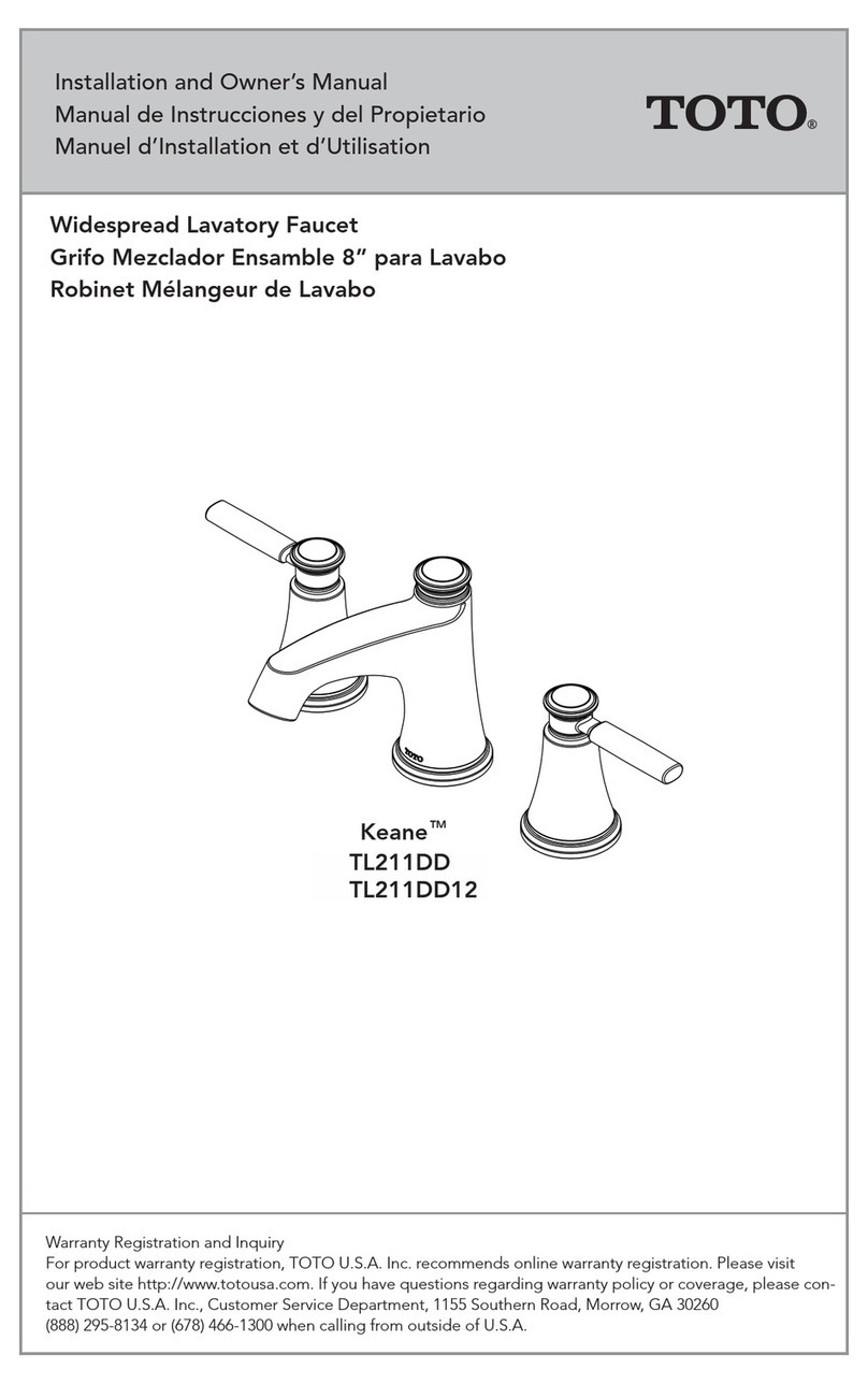
Toto Keane TL211DD Installation instructions

Toto

Toto Keane TL211DD Installation instructions

Toto TB100SFBN Installation instructions

Toto

Toto TB100SFBN Installation instructions

Toto Connelly TL221DD Installation instructions

Toto

Toto Connelly TL221DD Installation instructions

Toto Connelly TS221P Installation instructions

Toto

Toto Connelly TS221P Installation instructions

Toto TBP02201 User manual

Toto

Toto TBP02201 User manual

Toto Aimes TL626DD Installation instructions

Toto

Toto Aimes TL626DD Installation instructions

Toto WH099 Series User manual

Toto

Toto WH099 Series User manual

Toto Keane TS211T Installation instructions

Toto

Toto Keane TS211T Installation instructions

Toto Silas TB210DD Installation instructions

Toto

Toto Silas TB210DD Installation instructions

Toto Connelly TS221EV Installation instructions

Toto

Toto Connelly TS221EV Installation instructions

Toto PJS01W Technical manual

Toto

Toto PJS01W Technical manual

Toto Legato TL624DD Installation instructions

Toto

Toto Legato TL624DD Installation instructions

Toto TLP02301 User manual

Toto

Toto TLP02301 User manual

Toto RENESSE TL170SD Installation instructions

Toto

Toto RENESSE TL170SD Installation instructions

Toto TS101S Installation instructions

Toto

Toto TS101S Installation instructions

Toto Mercer TS756A Installation instructions

Toto

Toto Mercer TS756A Installation instructions

Toto STD TELS10 Series Installation instructions

Toto

Toto STD TELS10 Series Installation instructions

Toto TEN40AW V105 User manual

Toto

Toto TEN40AW V105 User manual

Toto Connelly TB221S Installation instructions

Toto

Toto Connelly TB221S Installation instructions

Toto ZA TLP03301U Installation instructions

Toto

Toto ZA TLP03301U Installation instructions

Toto EcoPower Automatic Faucets Installation instructions

Toto

Toto EcoPower Automatic Faucets Installation instructions

Toto Keane TL211SD Installation instructions

Toto

Toto Keane TL211SD Installation instructions

Toto Vivian TB220S Installation instructions

Toto

Toto Vivian TB220S Installation instructions

Toto TLP03301 User manual

Toto

Toto TLP03301 User manual

Popular Kitchen & Bath Fixture manuals by other brands

EuroSteam GE190001 quick start guide

EuroSteam

EuroSteam GE190001 quick start guide

Hans Grohe Talis Classic 14140 Series quick start guide

Hans Grohe

Hans Grohe Talis Classic 14140 Series quick start guide

Granberg 6310H installation instructions

Granberg

Granberg 6310H installation instructions

Kohler JULY 45352T-C9 installation instructions

Kohler

Kohler JULY 45352T-C9 installation instructions

Pfister Breckenridge LF-042-BC Quick installation guide

Pfister

Pfister Breckenridge LF-042-BC Quick installation guide

Hans Grohe Raindance Connect Showerpipe Eco 27166... Instructions for use/assembly instructions

Hans Grohe

Hans Grohe Raindance Connect Showerpipe Eco 27166... Instructions for use/assembly instructions

Hans Grohe Metris S 04135 0 Series Installation instructions / warranty

Hans Grohe

Hans Grohe Metris S 04135 0 Series Installation instructions / warranty

Hans Grohe Metris Select 260 14847000 Instructions for use/assembly instructions

Hans Grohe

Hans Grohe Metris Select 260 14847000 Instructions for use/assembly instructions

Kohler K-10412 Homeowner's guide

Kohler

Kohler K-10412 Homeowner's guide

Graff ATLANTIS 1100-C2 installation instructions

Graff

Graff ATLANTIS 1100-C2 installation instructions

Hans Grohe Rainfinity 26840180 Assembly instructions

Hans Grohe

Hans Grohe Rainfinity 26840180 Assembly instructions

Kohler PURIST 14406 installation instructions

Kohler

Kohler PURIST 14406 installation instructions

Graff G-11500 L2 Series installation instructions

Graff

Graff G-11500 L2 Series installation instructions

Santec Vantage I 2920EY-TM Installation instruction

Santec

Santec Vantage I 2920EY-TM Installation instruction

Sanipex BAGNO DESIGN BRISTOL BDM-BIS-413 Series installation guide

Sanipex

Sanipex BAGNO DESIGN BRISTOL BDM-BIS-413 Series installation guide

Spectrum Brands Pfister Briarsfield GT529-BF Quick installation guide

Spectrum Brands

Spectrum Brands Pfister Briarsfield GT529-BF Quick installation guide

GIANTEX KC52299 manual

GIANTEX

GIANTEX KC52299 manual

PELHAM & WHITE PWS231-B manual

PELHAM & WHITE

PELHAM & WHITE PWS231-B manual

manuals.online logo
manuals.online logoBrands
  • About & Mission
  • Contact us
  • Privacy Policy
  • Terms and Conditions

Copyright 2025 Manuals.Online. All Rights Reserved.