TouchIT LED Duo Q3 2014 User manual

TouchIT LED Duo
Manual
Q3 2014 Model - With EZ Connect
TouchIT Technologies

Chapter 1
TouchIT LED
Duo
Inside the manual you will learn all about the
TouchIT LED Duo models of Interactive LED.
For more information, please visit
www.touchittechnologies.com

IMPORTANT SAFETY INSTRUCTIONS
1. Please read these instructions carefully before using the product and keep them
safe for later reference.
2. Follow all warnings and instructions marked on the product.
3. Unplug this product from the wall outlet (power socket) before cleaning. Clean
the product with a damp soft cloth. Do not use liquid or aerosol cleaners as it may
cause permanent damage to the screen.
4. Caution of use varies from model to model; please observe appropriate
operation as per model in use.
5. Do not place this product on an unstable cart, stand, or surface which may
cause damage or harm to the product or individual.
6. Slots and openings on the cabinet, in the back cover or in the bottom, are for
ventilation; to ensure reliable operation and to prevent from overheating, these
openings must not be blocked or covered at any time. The openings should never
be placed near or over a radiator, heat source, or placed in a built-in installation
unless proper ventilation space (min. 2 inches/5cm of gap) is provided.
Section 1
IMPORTANT SAFETY INSTRUCTIONS
Please read these instructions carefully before
using the product and keep them safe for
future reference.
PLEASE NOTE :-
The TouchIT LED Duo has been designed to
be a MONITOR and NOT a Television. It does
not contain a TV Tuner of any description.
Safety Instructions
2

7. This product should be operated from the type of power
indicated on the marking label. If you are not sure of the type of
power available, consult your dealer or local service company.
8. This product is equipped with a 3-wire grounding type power
plug, a plug having a third (grounding) pin. This plug will only fit
into a grounding-type power outlet. This is a safety feature. If you
do not have proper outlet to insert the plug, contact your
electrician to replace your obsolete outlet. Do not break the
ground pin and circumvent the grounding.
9. Do not allow anything to rest, or persons to walk on the power
cord.
10. If an extension cord is used with this product, make sure that
the total ampere rating plugged into the extension cord does not
exceed the maximum ampere rating of the extension cord.
11. Never insert any object/tool of any kind through housing slots
of this product as they may touch dangerous voltage points or
short out components that could result in risk of fire or electric
shock. Never spill liquid of any kind on the product (except IP-
rated models).
12. Do not attempt to service this product yourself, always refer
to qualified or authorized person for the servicing of this product.
13. Unplug this product from the wall outlet and contact a
qualified service provider in the following circumstances:
When the power cord or plug is damaged, frayed or broken.
In the event that liquid has been spilled into the product (except
IP-rated models).
User/owner of this product is advised to keep all packaging
material for use in case for repackaging the unit for further
transportation, or for repair service which demands returned unit
to be properly packed in original packaging as well as proof of
purchase and other required documents per each warranty
instance.
3

1-1!About the Product
The TouchIT LED Duo is made of TFT LED panel and microprocessor-controlled
main board. It is designed to meet the demanding performance requirements of
education/schools, public premises, corporate, and industrial applications.
1-2!Notice
1.!Do not use any sharp object on the original LED panel surface if the model is
supplied without protective glass.
2.!Do not use corrosive or abrasive detergents, waxes or solvents for cleaning.
Use only a dry or damp cloth and use with clean water when cleaning.
3. Use qualified and safety-approved AC power cord only.
GENERAL FUNCTION
Display type: TFT-LCD MODULE DRIVE BOARD
RESOLUTION: UP TO 1920X1080 with a 16:9 ASPECT RATIO @60Hz
Section 2
CHAPTER CONTENTS
1-1!About the Product
1-2!Notice
1-3!Check List
Introduction
4

AUDIO/ VIDEO SIGNAL CONNECTIONS
□!SOURCE INPUT:
o!HDMI 1
o!HDMI 2
o!HDMI 3
o!VGA
□!SOURCE OUTPUT:
o!VGA(sometimes called “Pass Through”or”Loop Through”)
o!HDMI(For HDMI 1, HDMI 2 and HDMI 3)
□!AUDIO INPUT:
o!For VGA audio input.
□!AUDIO OUTPUT:
o!Audio output follow source.
DATA CONNECTIONS
USB A1 (A type)/ USB player, support formats listed in section
3-5-2
USB A2 (A type)/ USB Player, support formats listed in section
3-5-2
USB B1 (B type)/ only for connection touch control data to a user
PC
USB B2 (B type)/ only for connection touch control data to a user
PC
RS232 CONTROL input
AMBIENT LIGHT DETECT: to see detail in section 3-4(Option:
Light Sensor)
FREEZE: Freeze current picture on screen. (Freeze works with
under source VGA/ HDMI. Under source USB1/ USB2, please
press on handheld remote control to pause the picture)
Aspect Ratio
5

1-3!Check List
When opening the carton, please make sure that all the items
listed below are present:
1.!VGA cable (male-to-male) ×1
2.!Power cord ×1
3.!USB cable ×1(for touch monitor models only)
4.!HDMI cable x1
5.!Audio cable 3.5E x1
6.!User guide ×1 (e-file in CD and specific driver).
7.!Remote control x 1, battery included.
8.!Cleaning fabric x2
9.!Stylus x2
10.!Wall mount installation guide x1
If any items are missing or damaged, please contact your local
dealer immediately.#
Following items are optional at specific ordering:
11.!VGA cable (male-to-male) (optional) for VGA out application
Adapter/Converter Advisory
Should specific adapter/converter is required, i.e. tablet PCs, in
order to connect to this monitor, please use original adapter/
converter recommended by the original brand. The length of
cables should not be longer than 2 meters each.
6

2-1. Power cord connection:
Connect the power cord to the AC outlet.
2-2. Power on:
Switch on the main power of your monitor (switch is located next to the AC outlet)
2-3. Input Source VGA (HDMI1/ HDMI2/ HDMI3) Signal cable connection:
Plug one end of the 15-pin signal cable to the video signal connector at the rear of
the PC/laptop system (or engine box) and theother end to the monitor.
Or plug one end of the HDMI signal cable to signal source (PC, laptop, IPC, media
player of any kind with proper HDMI or other out port), and the other end to the
HDMI connector on the monitor.
Tighten the connector screws on both ends of the cable to secure good signal
connection.
2-4. VGA/ HDMI output connection (Optional male to male VGA/ HDMI cable):
Section 3
POWER AND SIGNAL CONNECTIONS
2-1. Power cord connection
2-2. Power on
2-3. Input Source VGA (HDMI1/ HDMI2/
HDMI3) Signal cable connection
2-4. VGA/ HDMI output connection (Optional
male to male VGA/ HDMI cable)
2-5. USB cable connection (for touch monitor
models)
Installing the TouchIT LED Duo
7

Plug one end of the VGA/ HDMI signal cable to signal source and
theother end to another VGA/ HDMI in connector to daisy-chain,
of cascading, signal to the other monitor.
Tighten the connector screws on both ends of the cable to secure
good signal connection.
2-5. USB cable connection (for touch monitor models):
Plug one end of the USB (B type) cable to the USB (A type)
connector at the rear of the (PC, or, IPC, or, media player), and
the other end to the USB connector on monitor.
There are two USB (B type) connecters, one for dynamic source
(VGA/ HDMI1/ HDMI2) on rear, the other for HDMI3 on side.
Please connect the signal source first, then follow by connecting
USB cable for touch.
8
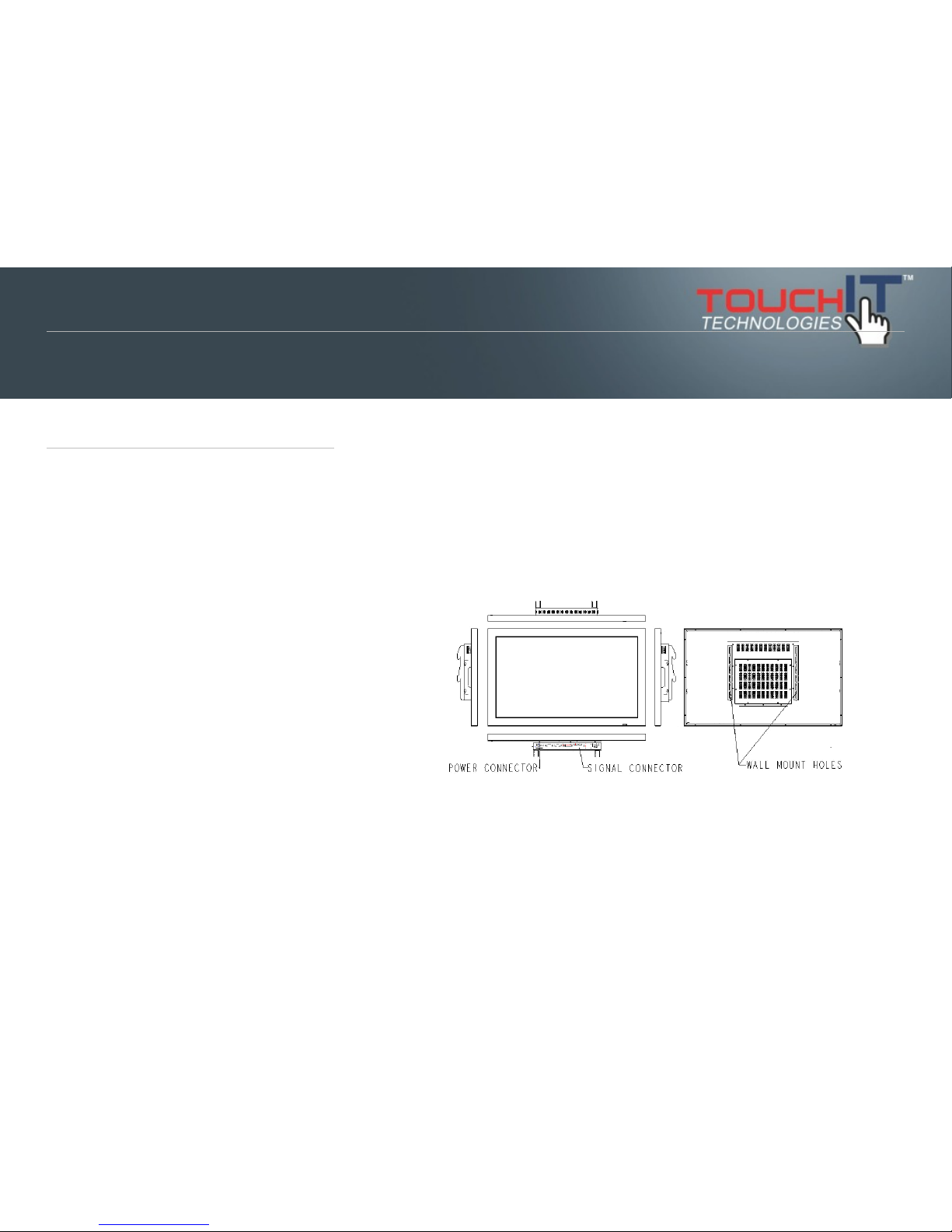
3-1 Get to know the monitor
The Monitor connectors are located on the rear side. They are shown in the
physical monitor as per the figure below and described in the following
paragraphs. Please note that connectors may vary in some derivative models,
please refer to individual model for special instructions.
!
Section 4
USING THE LED
3-1 Get to know the LED
3-2 Connector ports
3-3 Remote Control
3-4 Understanding the OSD Menu (with
Remote control)
3-5 Understanding the Keypad
Using the TouchIT LED Duo
9

3-2 Connector ports
The Figure below depicts the signal connectors on the main
board.
Rear
Side (EZ Connect)
3-3 Keypad
Front View
Bottom View
3-4 Remote Control
The remote control is shown in the drawing below.
10

Size: 197.2 x 47.1 x 23.2mm (7.7 x 1.85 x 0.9 x in.)
Operation distance: > 10 meter (32ft.)
Working angle: not more then +/- 40 degree
3-4 Understanding the OSD Menu(with Remote control)
a. Power
Press the power button to turn on/offthe monitor.
b. HDMI 1
Press this button to select the HDMI 1signal source.
c. HDMI 2
Press this button to select the HDMI 2signal source.
d. HDMI 3
Press this button to select the HDMI 3signal source.
e. Touch
Press the Touch to turn ON/OFF Touch function
f. VGA
Press this button to select the VGA signal source. Source default
is at VGA source.
!
g. Picture
Press the Picture to select Zoom mode.
h. USB 1
Press this button to select the USB 1 signal source.
i. USB 2
Press this button to select the USB 2 signal source.
11

j. Vol.+/ Vol.-
Press Vol.+/ Vol- to adjust Volume UP/ DOWN.
k. Mute
Press this button to mute or un-mute.
l. Misc.
Reserved
m. Freeze
Press this button to Freeze picture on screen.
n. Auto
Press this button to auto-adjust and optimize picture screen of
the monitor.
o. Select function for adjustment
Press the (▲/▼/Enter) button to scroll up and down the intended
function items for adjustment, and then press the Enter button to
activate that function item.
p. Menu
Press the Menu button to go into OSD menu.
q. Exit
Press Exit button to exit setting, or, exit OSD menu. Alternatively,
press “Menu” button to exit the OSD Menu instantly at any time.
r. Info.
Press to show timing and resolution
s. USB Function
Press to control
USB function.
12

3-4 Content of OSD Menu
Picture!// press / (UP/Down) to select sub
menu, press / to next page(Sound/ Option)
λ! Picture mode!
!!Contrast! !
!!!Brightness
!!!Color
!!!Sharpness
!!!Tint
!
λ! Color Temperature!
!!!Standard! !
!!!Cool
!!!Medium
!!!Warm
λ! Aspect Ratio
λ! Noise reduction
λ! PC Setup
Auto Adjust
λ! Backlight
!
Sound
λ! Sound mode
!!!User
!!!!Treble
!!!!Bass
13

!!!Standard
!!!Music
!!!Movie
!!!Sports
!
λ! Balance
λ! Auto Volume (Auto Gain Control)
Volume up
Volume down
Option
λ! OSD Language
English
Français
Español
Português
Arabic
中文(Simple)
λ!Restore Factory Default
λ! Blending (OSD transparency)
λ! Light Sensor ON/ OFF(When this function has been turned
ON, the Monitor will automatically adjust back light(Luminance).
Adjusting the luminance automatically has three stages. The light
sensor is located with IR sensor.)
λ! Auto Detect ON/ OFF (When this function has been turned
ON, the Monitor will automatically seeking signal form input
sources (status standby mode).
λ! OSD Duration
OFF
14
5 sec.
10 sec. (Factory Default)
15 sec.
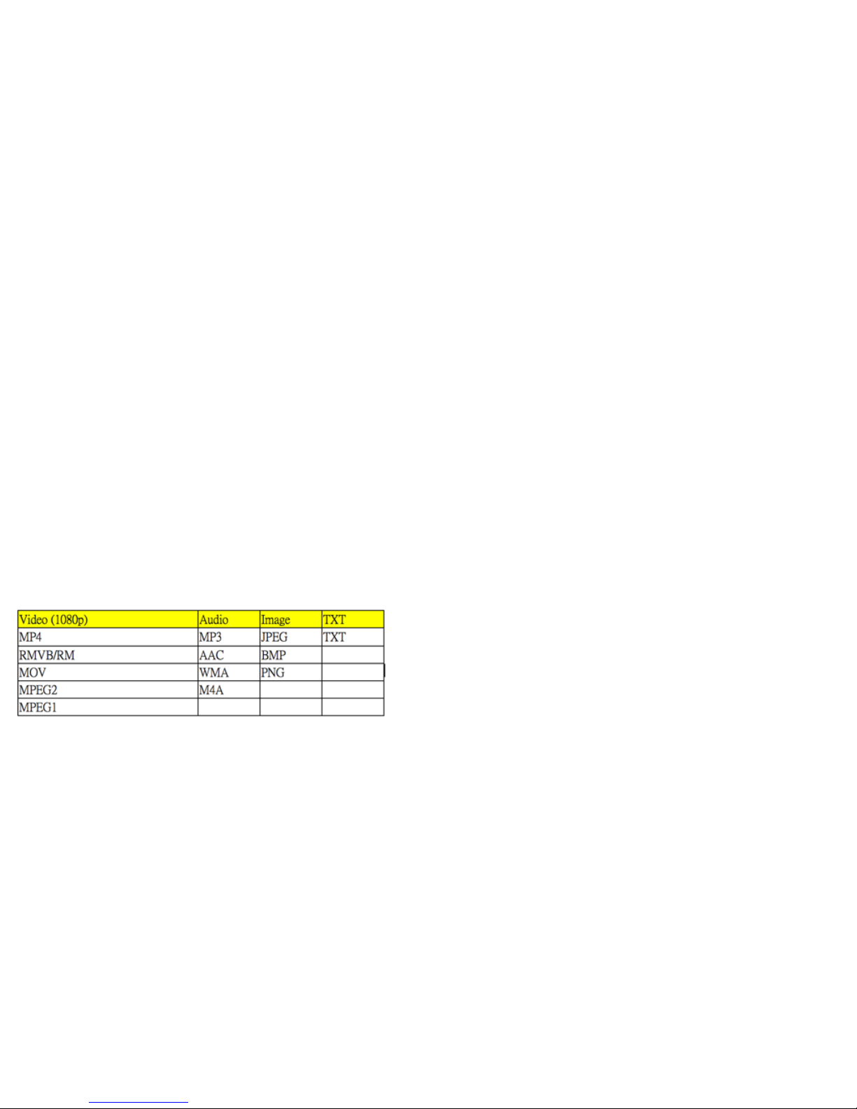
3-5 USB
3-5-1 USB F/W Update (please call technical support)
3-5-2 USB Player Support Format
Note: It will take a while to load data from your USB (USB Hard
Drive). The more data in the hard disk are, time is the longer if
read.
Note: When video comes out only picture without audio, it could
be audio format doesn’t support or over range of audio bit rate.
Note: The Keypad doesn’t support full function of USB menu.
Please to use remote control.
3-6 RS232 Command
3-6-1 Introduction
This document is the communication protocol between the
Monitor and PC Via RS232.
3-6-2 Data format
15
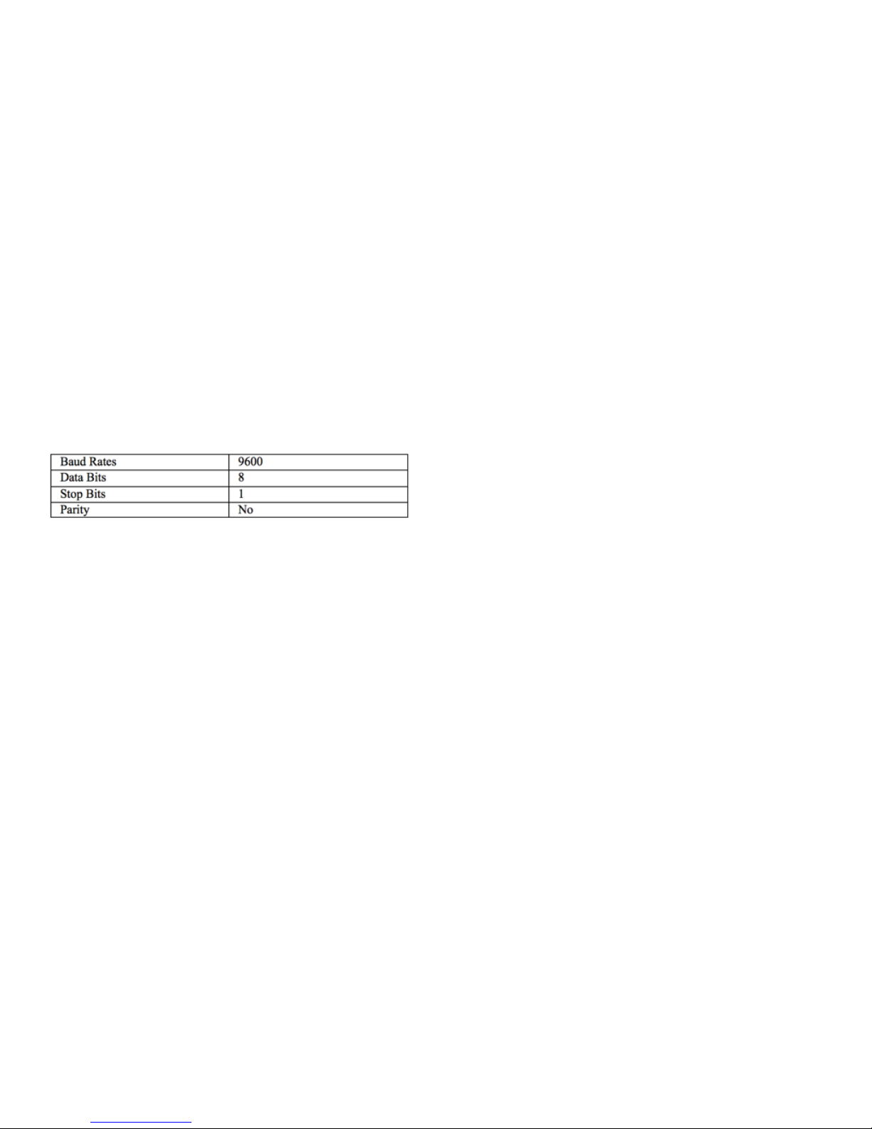
Data will be transferred serially according to RS232 protocol
using the following settings.
Female DB9DCE pin numbering and definitions: recommended
communication rates are: (higher baud rates are fine but 9600 is
by far the most common and is sufficient for the volume of data
being transmitted)
3-6-3 Data structure
Note•All numbers shown are in the protocol description are in
string unless indicated otherwise. Percentages are shown in
decimal.
General Command Form
•STX. The first character is the standard Start of Text (STX)
character ‘S’.
•Address. The second character is the device address. If a device
does not support addressing, these should be 0 and 9 to act as
the global address.
•Type. The third character is the command type. There are four
types of commands:
o Command0
o Ack1
o Nak2 (option)
o Notification 3 (option)
•Property ID. The four and fifth and characters are the property
identifier. By using one byte we have 256
•Data Length. The sixth character is the number of characters in
the parameter data section.
•Data. Following the sixth character is the parameter data section
that is as many characters long as the sixth character indicates. If
the sixth character is 00 (as with the Reset command for
example) then there are no characters in the parameter section.
16
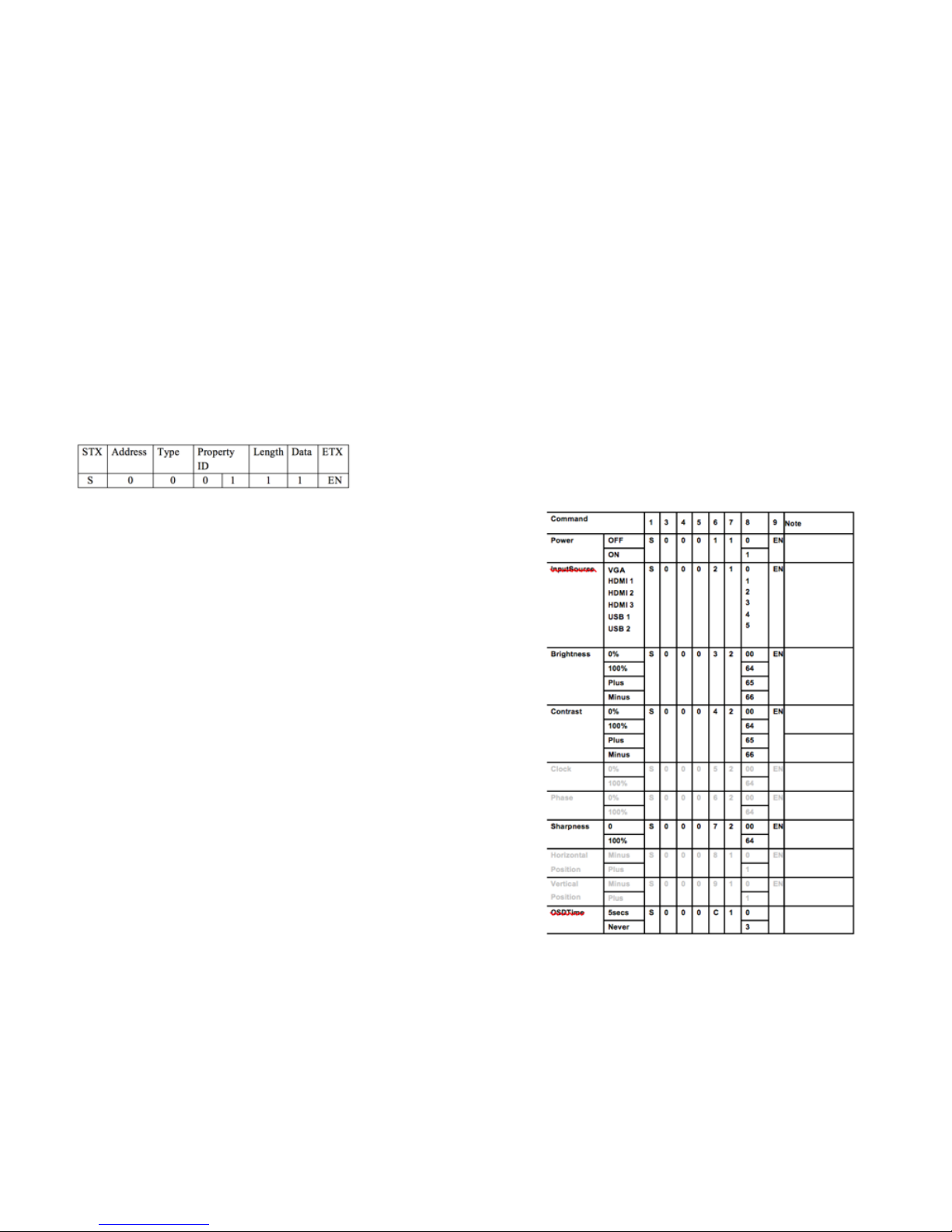
This parameter section contains the value (hexadecimal) for the
property.
•ETX. The last character is the standard End of Text (ETX) ‘EN’.
Sample:
In this example (Power On to everything), the Address character
0, which is the global address for all devices connected to the
serial port. The Type character is 0 to indicate the transmission is
a command. The Property ID characters indicate a property
identifier of 1, which in this protocol is the value for power. The
Length character is a 1, which indicates that there is one
character of data associated with this command. The Data has a
value of 1, which is the value for ON. The ETX is command End
code.
3-6-4 Command code
3-6-4-1 User Command
In the following samples, the global device address of 0 issued.
The numbers in brackets are the string value that has associated
with the property or the property value.
Note that these values are used in the command string.
For the properties that support ranges such as brightness and
volume, examples are provided for low, and high. Any intervening
values can be deduced from these.
This section only covers the commands sent from the computer
to the device. For responses from the device, see sections
3-6-4-2–ACKs/Notifications.
17
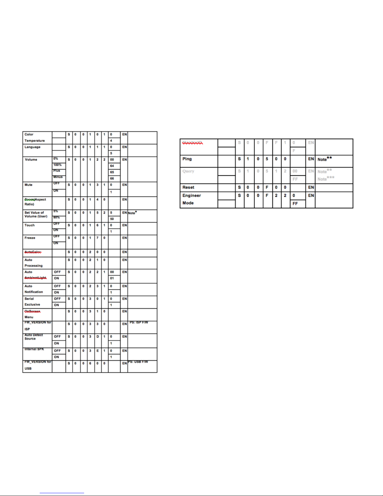
Note*do reset this value will be set as default 15. it works on
power on status.
Note**the system doesn’t allow to“Ping/Query/BulkQuery”more
than one device at one time.
Note*** if your system need “Query” function, please contact
engineer. It’s a standard function.
18

Installation
This stand is included for 32” and is optional for all other sizes.
1.!Find the appropriate stand, take out the packaging and use the bolts
included to install the back plate first.
!
Section 5
INSTALLING THE STAND
The stand is included with the 32” TouchIT
LED Duo, but a table top stand is available for
all other sizes up to 84”
Installing the Stand & Wall Mounts
19
Table of contents


