Tour Links Mini Link User guide

Mini Links Set Up Manual
Tools Required:
Phillips Screwdriver
1-866-92-1-PUTT
7888
www.tourlinks.net
English
MG-COIM-1
3
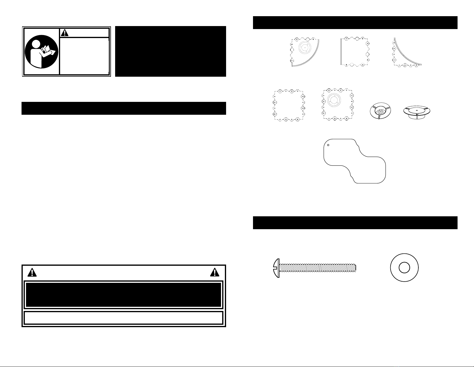
PARTS IDENTIFIER
HARDWARE IDENTIFIER (ACTUAL SIZE)
2. Straight Edge Panel
P2-SE
1. Single Curve Panel
P2-ORSCE
8. Turf
7. Filler Plate
A2-CFPA
3. Inside Radius Panel
P2-IRSCE
4. Panel-Center
P2-IC
6. Cup
A2-FCA
5. Panel-Center-With Cup
P2-ICC
2
INDOOR/OUTDOOR PLAY
Different outdoor and indoor environment elements will cause possible expansion and
contraction of the turf and the base. This putting green was designed to be used for play
both indoors and outdoors.
Assemble on level surface: For optimal play, assemble on a hard, flat surface. The base
is made of a strong material but over a long period of time will relax to conform to the
level of the surface underneath. The green will only be as level as the surface below. If
the surface is not level, measures may be taken to construct a level playing surface.
Portability: All of the panels interlock for ease of assembly and disassembly. To move or
store the putting green you must disassemble EACH interlocking panel from each other
for safety in moving. Two people are required for safe assembly and disassembly.
Moving cup: The mobility of the cup was designed so the cup could always be lined up
under the hole cut outs of the turf. The cup will not move during play.
Drainage: Spacing between the joints of the panels allows the drainage of water off the
deck when used outdoors.
IMPORTANT! Remove all contents from boxes.
NOTICE TO ASSEMBLERS
ALL Tour Links Putting Green Systems,
including those used for DISPLAYS, MUST
be assembled with fasteners according
to the instructions. Failure to follow
instructions could result in INJURY.
READ AND UNDERSTAND
OPERATOR’S MANUAL
BEFORE USING THIS UNIT.
FAILURE TO FOLLOW
OPERATING INSTRUCTIONS
COULD RESULT IN INJURY
OR DAMAGE TO PROPERTY.
WARNING!
Please register this product online at www.tourlinks.net
SAFETY INSTRUCTIONS
• Two(2)peoplearerecommendedforthisoperation.
• Thelifeofyourputtinggreendependsonmanyconditions.Theclimate,placementofthe
green,exposuretocorrosivessuchaspesticides,herbicides,orsaltsareallimportantfactors.
• IftechnicalassistanceisrequiredcontactTourLinks.
Most injuries are caused by misuse and/or not following instructions.
Use caution when using this system.
9. Stainless Steel Screw 10. Stainless Steel Washer
54
IMPORTANT: Refer to THE PRODUCT IDENTIFICATION PAGE
IMPORTANT: Refer to THE PRODUCT IDENTIFICATION
PAGE
on page 3 of this manual to insure proper panel layout.
Slide deck panels together piece by piece.
After the first few panels have been locked together, the best method
for sliding the remaining panels together is to kneel on the assembled
section and pull the next panel in towards you to engage the teeth.
Pulling the panels into place is far easier then trying to push them into
place. Please see drawing #3 on page 6 which indicates the angle to pull
a new panel into position when surrounded by locked panels. Use your
pre-cut turf as the template to gauge whether or not the panels need to
be pushed tighter or spread apart. It is important that the turf be allowed
to lay flat in a warm environment for several hours prior to installation to
achieve a relaxed state in the fibers. This will allow the turf to return to
its proper size.
After all the panels have been installed in their proper configuration lay
the relaxed turf on to the panels to check turf fit and slide the panels
together or pull them apart to create a gap of around 1/16 inch between
the turf edge and the panel bump rail. Please note that with time the turf
will tend to shrink a bit due to the natural tendencies of textiles. We have
attempted to make the turf fit in all conditions, but due to manufacturer
allowed tolerances, it may be necessary to trim the carpet to achieve
proper fit. This trimming should only be done if the panels have all been
spread to their maximum adjustability and the turf is still tight. After the
panels have been adjusted to the turf size, temporarily remove the turf.
Insert the self tapping screws and washers into the locations indicated
on page 3. Hand start each screw and then tighten with a screwdriver or
power driver. DO NOT OVER TIGHTEN. Once tight, back the screws off by
one-quarter turn to allow the panels to move freely during expansion and
contraction. Some models come with additional screws and washers to
be used at the installers discretion. See attached layout sheets for screw
locations. Our experience shows that the number of screws indicated
achieves the best results.
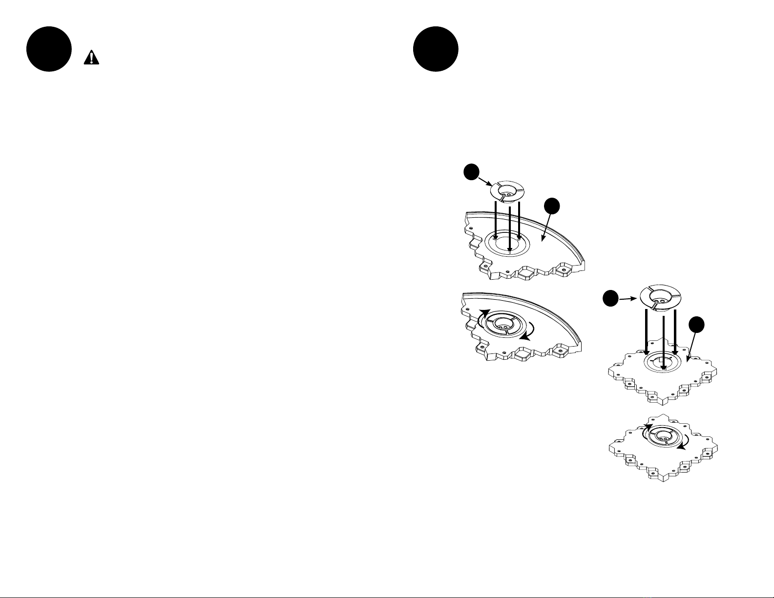
1Install the cup assemblies in all the panels that are indicated having cups.
Insert the cups into the panels and twist. The cup is now able to move in a
complete circular orbit to allow for expansion and contraction of both the
panels and the turf.
Locate any corner panels that do not have a cup assembly and insert a filler
plate. Install using the same method as described with the cups.
2
6
1
6
5
6 7
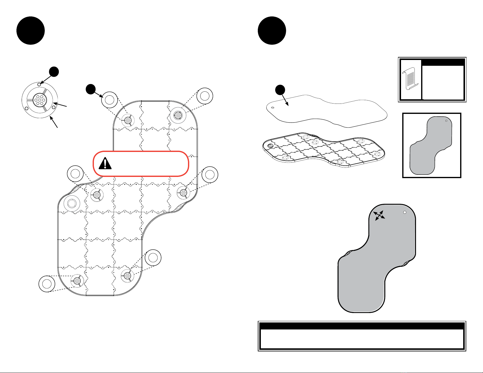
Position deck washers (11) around cups and into the circular indent on the
deck using the double sided deck washer tape (19) as shown.
NOTE: Filler plates do not require deck washers.
3
Cup
Circular indention
on the deck panel
19
11
This illustration is representative only.
Refer to The Product Identification
page on page 5 of this manual to
insure proper panel layout.
Unroll and Install the relaxed turf (8) as shown.
Make sure hole in turf lines up with the cup.
4
8
Use care when
installing or moving
tUrf. never crease
tUrf.
when assembled, it is
sUggested to allow 24
hoUrs for assembled
Unit to settle
NOTE:
TOP VIEW
Cups can be moved in
any direction to line
up with holes in turf.
CupAdjustment:
for Permanant installation of mini linKs follow the
“toUr linKs Permanant installation gUide”
NOTE

8 9
BACKYARD INSTALLATION
If you are installing the green in the backyard, or other natural outdoor areas,
we have a few techniques that will speed up the installation. The Tour Links®
panels are designed to flow over the existing ground slope that is naturally
created in the earth.
If a particular valley is too severe then some filling with finely crushed stone
in these areas is recommended. If a hill is too severe, a little digging may be
required.
Remember most golf greens are not dead flat.
1. Place your pre cut turf, green side up, on the grass in the desired location.
It is important that your turf be allowed to relax in a warm environment
for several hours to assure the best fit.
2. Walk around the edge of the turf with a bottle of baby powder or chalk
and mark the grass around the pre cut turf creating an outline of the
green.
3. Remove the synthetic turf.
4. Use a weed whacker to scalp the grass as low as possible within the
outline of the green. This will give you a great base to start with.
5. Now follow your “Tour Links Design Sheet” and begin to layout the
panels.
6. Assemble the panels per the Tour Links Assembly Instruction Manual. Be
sure to build your panels to the dimensions of the pre-cut turf, due to the
natural shrinkage that occurs in all textiles. There should be about 1/16”
gap around the edge. This gap will vary as temperatures and natural
shrinkage occur. You must only use the provided screws & washers for all
INSTALLATION TIPS
When placed on sloped ground, Tour Links panels are designed to flex
and mimic the underlying sloped ground creating a realistic putting
green. When placed on a flat and level surface, Tour Links panels will
remain flat and level.
The easiest method of installation of the Tour Links®system is indoor
or outdoor on a hard surface. Whether it is tile, carpet, or a wooden
deck, this installation requires nothing more than sliding the panels
together and tightening the provided screws and washers. Almost
immediately the space is transformed into a professional putting
green.
installations and DO NOT over tighten the screws. Use just enough force
to snug the screws down and then back off a quarter turn. You will only
need to insert the screws in the holes of the outer panel as shown on
page 3. There are a few additional screws provided to be used in areas
of the green that are following a severe contour. Use these screws to
insure proper alignment in necessary. If you are installing over sand or
soil areas a layer of commercial polyester fabric weed barrier cloth should
be laid out under the panels to prevent sand or dirt from interfering with
assembly of the panels. This weed barrier cloth should also be used if you
are installing over grass. It is believed that this cloth will help minimize
any uneven settling of the panels. Be sure to either weed wack the
grass down to bare dirt or kill the grass with a liquid weed killer prior to
installation of the weed control cloth and the panels.
7. As you are laying out the panels and you come to a panel with a hole
make sure the hole is positioned in the correct location. The center panel
is designed to allow for 4 different hole locations depending on which
way the panel is installed.
8. If you are installing on a contoured surface, water may tend to settle in
some low areas along the bump rails of the curved panels.
9. Locate the low areas by flowing water over the panels and watch where
it collects. Rolling a golf ball on the panels will also indicate the low
areas.
10. At the identified low area, 1/2” away from the bump rail, drill a 3/8”
hole through the deck material. This will allow any collected water to
funnel out of the low area. Repeat the drilling at all identified low water
collection areas. This step may not be necessary depending on your
location.
11. Your green may seem a little spongy at first, but as the panels settle,
the green will become very stable. A solid base could be achieved
immediately by spreading and compacting a 1” layer of finely crushed
rock, such as decomposed granite or crushed limestone. Pack down the
rock and lay out the panels. This is where a layer of commercial polyester
fabric weed barrier cloth is required to keep the new gravel or sand
from getting caught in the panel teeth, disrupting the expansion and
contraction of the panels. NOTE: Polyester weed barrier cloth is available
at most home centers.
12. Install the turf as described in step 4 on page 9 of this manual.
13. Periodic vacuuming of the turf is recommended, as well as washing the
bump rails. To clean the bump rails, use any automotive black bumper
conditioner found in any auto parts store.
BACKYARD INSTALLATION
10 11
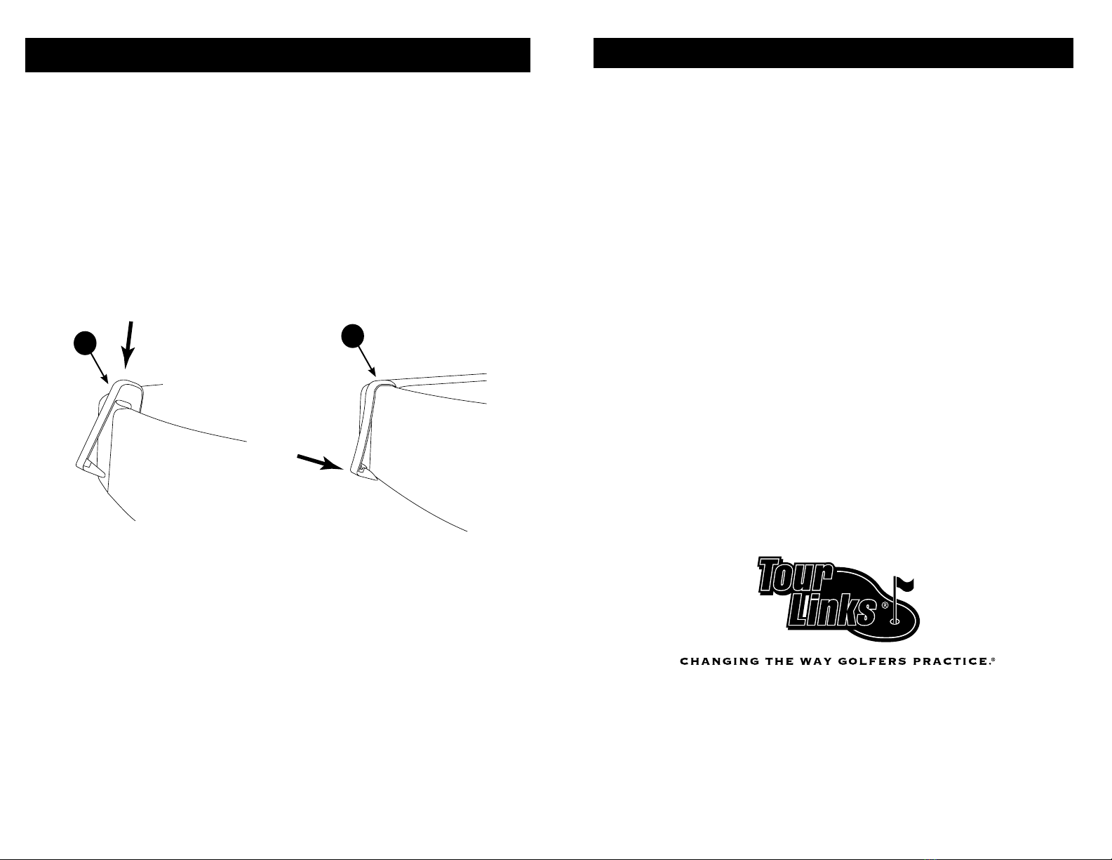
BUMP RAIL CLIP INSTALLATION
Once the entire green has been assembled, with the turf fitting 1/6-inch
away from the bump rail, it’s time to install the bumper clips. The small black
plastic clips are designed to attach over the bump rails at the seams. This is
an aesthetic feature that hides the gaps that may have been created during
installation in order to ensure proper turf fit. Place the clips over the bump
rail and push down on top of the clip until it follows the contour of the bump
rail and then push the clip into the side of the bumper rail. There is a small
molded prong on the bottom of the clip which will attach to the lower edge
of the panel. The clip is designed to slide back and forth in the seam during
expansion and contraction. To remove the clip simply lift up the panel and
disengage the prong.
20 20
GENERAL CARE AND MAINTENANCE
• Cleanpanelswithasoftdampcloth.Carefullysweep
or vacuum turf. To clean the bump rails, use any
automotive black bumper conditioner found in any
auto parts store.
• Whenrollingupturfforstorage,alwaysrollloosely
with green-side out.
• Donotcreaseturf.
• Foroutdoorapplication:Ifunitwillnotbeinusefor
an extended period of time, roll turf with green side
out and store turf and accessory pieces indoors.
• Disassembleunitbeforemoving.
1-866-92-1-PUTT
7888
www.tourlinks.net

131212
IMPORTANT: IDENTIFY PROPER HOLE BEFORE PROCEEDING WITH ASSEMBLY.
Use the diagrams on the following pages for proper individual hole set up .
PRODUCT IDENTIFICATION PAGE
1 - Straight Shot page 13
2 - Off the Wall page 14
3 - Big Blue page 15
4 - Between the Yellow Lines page 16
5 - Zig Zag page 17
6 - Take Dead Aim page 18
7 - Narrow Path page 19
8 - Gum Drop Lane page 20
9 - Around the Corner page 21
10 - Take Your Pick page 22
11 - The Snake page 23
12 - Tight Squeeze page 24
13 - Stop and Go page 25
14 - Keep to the Left page 26
15 - Landing Zone page 27
16 - Point to Point page 28
17 - Tight Turn page 29
18 - Hold Your Breath page 30
IMPORTANT: IDENTIFY PROPER HOLE BEFORE PROCEEDING WITH ASSEMBLY.
Follow the diagram below for proper hole set up .
PRODUCT IDENTIFICATION PAGE
Hole 1 - Straight Shot
Parts List
4 Straight Edge Panels
4 Center Panels
1 Center Panel with hole
8 Single Curve Panels
4 Inside Radius Panels
1 Cup
8 Filler Plates
Bolts and Washers

1514
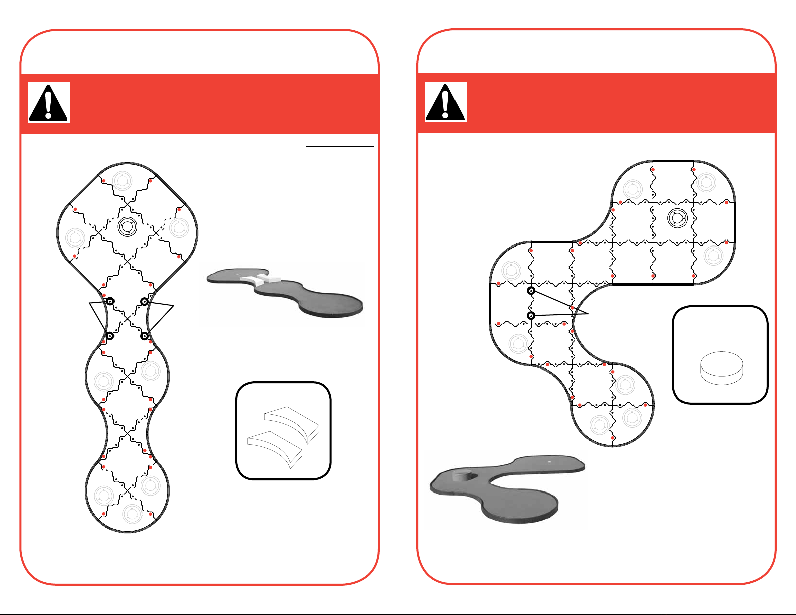
IMPORTANT: IDENTIFY PROPER HOLE BEFORE PROCEEDING WITH ASSEMBLY.
Follow the diagram below for proper hole set up .
PRODUCT IDENTIFICATION PAGE
Hole 2 - Off the Wall
Prop Mounting Points
Optional Prop
Parts List
12 Straight Edge Panels
2 Center Panels
1 Center Panel with hole
6 Single Curve Panels
2 Inside Radius Panels
1 Cup
6 Filler Plates
Bolts and Washers
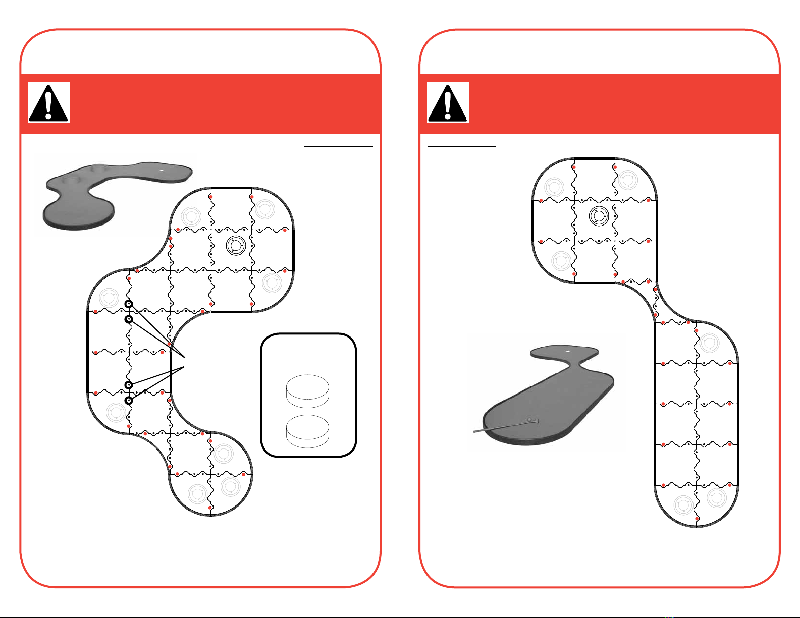
IMPORTANT: IDENTIFY PROPER HOLE BEFORE PROCEEDING WITH ASSEMBLY.
Follow the diagram below for proper hole set up .
PRODUCT IDENTIFICATION PAGE
Hole 3 - Big Blue
Prop Mounting Points
Prop Mounting Points
Parts List
14 Straight Edge Panels
2 Center Panels
1 Center Panel with hole
6 Single Curve Panels
2 Inside Radius Panels
1 Cup
6 Filler Plates
Bolts and Washers
Optional Props
1716
IMPORTANT: IDENTIFY PROPER HOLE BEFORE PROCEEDING WITH ASSEMBLY.
Follow the diagram below for proper hole set up .
PRODUCT IDENTIFICATION PAGE
Hole 4 - Between the Yellow Lines
Prop Mounting Points Prop Mounting Points
Optional Props
Parts List
4 Straight Edge Panels
4 Center Panels
1 Center Panel with hole
8 Single Curve Panels
4 Inside Radius Panels
1 Cup
8 Filler Plates
Bolts and Washers
IMPORTANT: IDENTIFY PROPER HOLE BEFORE PROCEEDING WITH ASSEMBLY.
Follow the diagram below for proper hole set up .
PRODUCT IDENTIFICATION PAGE
Hole 5 - Zig Zag
Optional Prop
16” Cylinder
Prop Mounting Points
Parts List
6 Straight Edge Panels
5 Center Panels
1 Center Panel with hole
8 Single Curve Panels
4 Inside Radius Panels
1 Cup
8 Filler Plates
Bolts and Washers

1918
IMPORTANT: IDENTIFY PROPER HOLE BEFORE PROCEEDING WITH ASSEMBLY.
Follow the diagram below for proper hole set up .
PRODUCT IDENTIFICATION PAGE
Hole 6 - Take Dead Aim
Prop Mounting Points
Optional Props
2 - 12” Cylinders
Parts List
4 Straight Edge Panels
4 Center Panels
1 Center Panel with hole
8 Single Curve Panels
4 Inside Radius Panels
1 Cup
8 Filler Plates
Bolts and Washers
IMPORTANT: IDENTIFY PROPER HOLE BEFORE PROCEEDING WITH ASSEMBLY.
Follow the diagram below for proper hole set up .
PRODUCT IDENTIFICATION PAGE
Hole 7 - Narrow Path
Optional Prop
Prop Mounting Points
Parts List
12 Straight Edge Panels
1 Center Panel with hole
6 Single Curve Panels
2 Inside Radius Panels
1 Cup
6 Filler Plates
Bolts and Washers

2120
IMPORTANT: IDENTIFY PROPER HOLE BEFORE PROCEEDING WITH ASSEMBLY.
Follow the diagram below for proper hole set up .
PRODUCT IDENTIFICATION PAGE
Hole 8 - Gum Drop Lane
Optional Props
12” Cylinder
16” Cylinder
8” Cylinder
Prop Mounting Points
Parts List
14 Straight Edge Panels
2 Center Panels
1 Center Panel with hole
5 Single Curve Panels
1 Inside Radius Panel
1 Cup
5 Filler Plates
Bolts and Washers
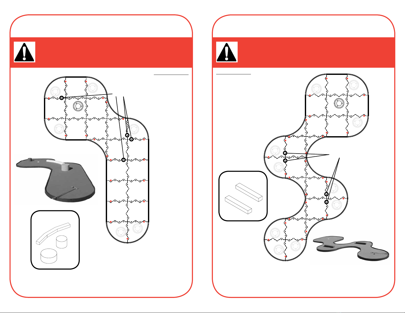
IMPORTANT: IDENTIFY PROPER HOLE BEFORE PROCEEDING WITH ASSEMBLY.
Follow the diagram below for proper hole set up .
PRODUCT IDENTIFICATION PAGE
Hole 9 - Around the Corner
Optional Props
Prop Mounting Points
Prop Mounting Points
Parts List
10 Straight Edge Panels
4 Center Panels
1 Center Panel with hole
8 Single Curve Panels
4 Inside Radius Panels
1 Cup
8 Filler Plates
Bolts and Washers
2322
IMPORTANT: IDENTIFY PROPER HOLE BEFORE PROCEEDING WITH ASSEMBLY.
Follow the diagram below for proper hole set up .
PRODUCT IDENTIFICATION PAGE
Hole 10 - Take Your Pick
Prop Mounting Points
Optional Props
Parts List
10 Straight Edge Panels
4 Center Panels
1 Center Panel with hole
6 Single Curve Panels
2 Inside Radius Panels
1 Cup
6 Filler Plates
Bolts and Washers
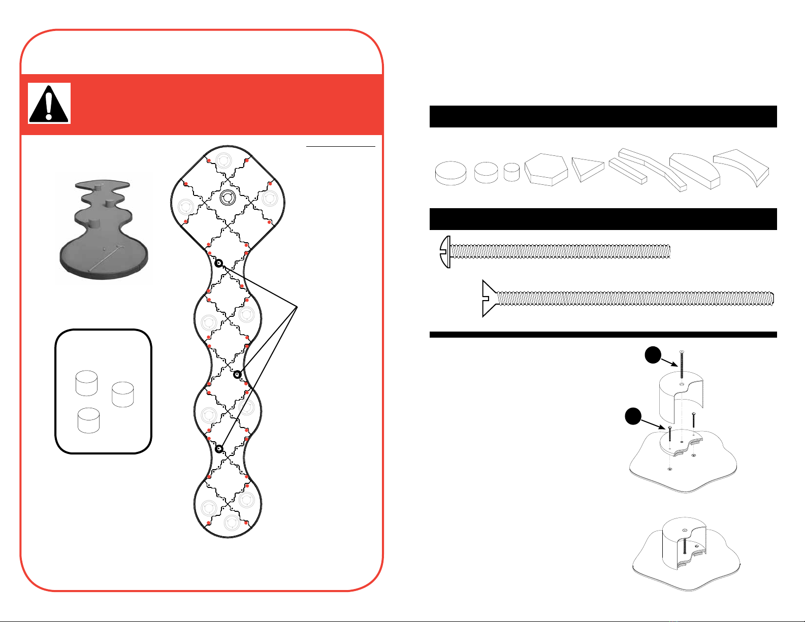
IMPORTANT: IDENTIFY PROPER HOLE BEFORE PROCEEDING WITH ASSEMBLY.
Follow the diagram below for proper hole set up .
PRODUCT IDENTIFICATION PAGE
Hole 11 - The Snake
Optional Props
Prop Mounting Points
Parts List
4 Straight Edge Panels
6 Center Panels
1 Center Panel with hole
10 Single Curve Panels
6 Inside Radius Panels
1 Cup
10 Filler Plates
Bolts and Washers
2524
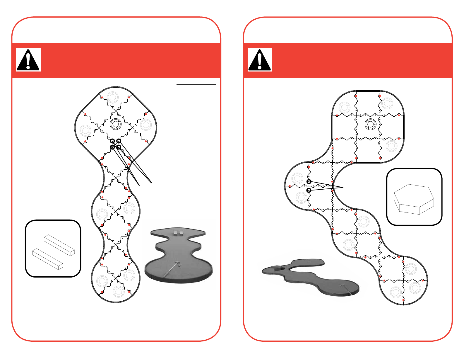
IMPORTANT: IDENTIFY PROPER HOLE BEFORE PROCEEDING WITH ASSEMBLY.
Follow the diagram below for proper hole set up .
PRODUCT IDENTIFICATION PAGE
Hole 12 - Tight Squeeze
Optional Props
Prop Mounting Points
Parts List
4 Straight Edge Panels
4 Center Panels
1 Center Panel with hole
8 Single Curve Panels
4 Inside Radius Panels
1 Cup
8 Filler Plates
Bolts and Washers
IMPORTANT: IDENTIFY PROPER HOLE BEFORE PROCEEDING WITH ASSEMBLY.
Follow the diagram below for proper hole set up .
PRODUCT IDENTIFICATION PAGE
Hole 13 - Stop and Go
Prop Mounting Points
Optional Prop
Parts List
4 Straight Edge Panels
6 Center Panels
1 Center Panel with hole
10 Single Curve Panels
6 Inside Radius Panels
1 Cup
10 Filler Plates
Bolts and Washers
2726
IMPORTANT: IDENTIFY PROPER HOLE BEFORE PROCEEDING WITH ASSEMBLY.
Follow the diagram below for proper hole set up .
PRODUCT IDENTIFICATION PAGE
Hole 14 - Keep to the Left
Optional Prop
Prop Mounting Points
Parts List
12 Straight Edge Panels
5 Center Panels
1 Center Panel with hole
6 Single Curve Panels
2 Inside Radius Panels
1 Cup
6 Filler Plates
Bolts and Washers
IMPORTANT: IDENTIFY PROPER HOLE BEFORE PROCEEDING WITH ASSEMBLY.
Follow the diagram below for proper hole set up .
PRODUCT IDENTIFICATION PAGE
Hole 15 - Landing Zone
Prop Mounting Points
Optional Props
Parts List
4 Straight Edge Panels
6 Center Panels
1 Center Panel with hole
10 Single Curve Panels
6 Inside Radius Panels
1 Cup
10 Filler Plates
Bolts and Washers
2928
IMPORTANT: IDENTIFY PROPER HOLE BEFORE PROCEEDING WITH ASSEMBLY.
Follow the diagram below for proper hole set up .
PRODUCT IDENTIFICATION PAGE
Hole 16 - Point to Point
Prop Mounting Points
Optional Props
2 - 16” Cylinders
Parts List
6 Straight Edge Panels
6 Center Panels
1 Center Panel with hole
8 Single Curve Panels
4 Inside Radius Panels
1 Cup
8 Filler Plates
Bolts and Washers
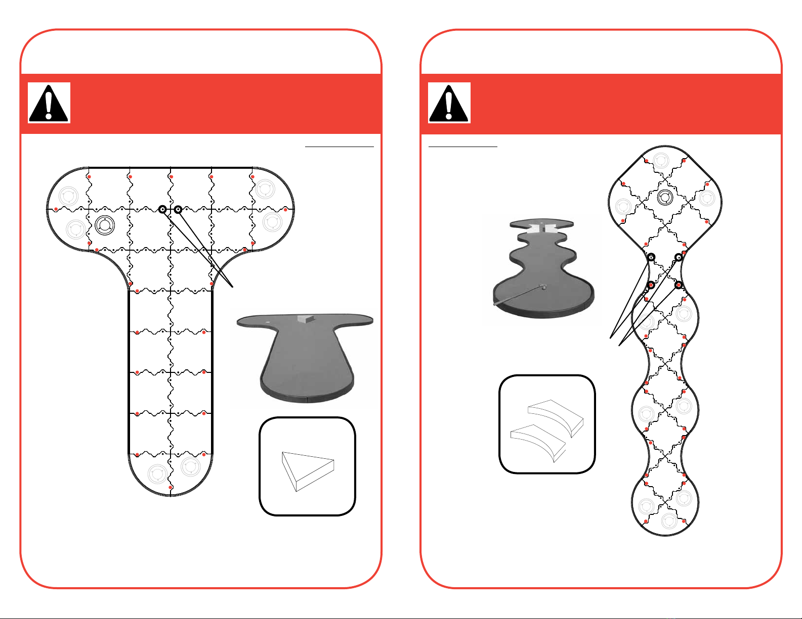
IMPORTANT: IDENTIFY PROPER HOLE BEFORE PROCEEDING WITH ASSEMBLY.
Follow the diagram below for proper hole set up .
PRODUCT IDENTIFICATION PAGE
Hole 17 - Tight Turn
Parts List
12 Straight Edge Panels
1 Center Panel with hole
6 Single Curve Panels
2 Inside Radius Panels
1 Cup
6 Filler Plates
Bolts and Washers
3130
IMPORTANT: IDENTIFY PROPER HOLE BEFORE PROCEEDING WITH ASSEMBLY.
Follow the diagram below for proper hole set up .
PRODUCT IDENTIFICATION PAGE
Hole 18 - Hold Your Breath
Prop Mounting Points
Optional Props
3 - 8” Cylinders
Parts List
4 Straight Edge Panels
6 Center Panels
1 Center Panel with hole
10 Single Curve Panels
6 Inside Radius Panels
1 Cup
10 Filler Plates
Bolts and Washers
Each Mini Links prop is designed with
an interior plate that aligns to existing
mounting points of the panels. (See each
hole layout for exact location of mounting
points) Locate the prop style and placement
of the props for each hole and attach the
proper mounting plate to the panel system
using the 1/4” bolts. You will see that the
mounting holes have been pre-cut into the
turf to insure proper placement .
Once the interior plates are secured,
simply slide the prop over the plate
and attach with the 3/8” mounting bolt
PROPS IDENTIFIER
HARDWARE IDENTIFIER
2. Extra Long 3/8” Mounting Bolt (1)
Bolt length is different for each prop
1. Stainless Steel 1/4” x 3” Screw (2)
MiniLinks props are manufactured in aluminum to our exact specifications
and powder coated with a tough finish which will last for years of outdoor fun.
Prop Installation
2
1

32
Warranty
Seller warrants that the equipment delivered by seller will be of the kind
and quality described in the order or contract and will be free of defects in
workmanship or material. Should any failure to conform to this warranty appear
within three years seller shall,on notification, correct such nonconformity,
including nonconformance with the specifications, at its option, either by
repairing any defective part or parts, or by making available F.O.B. sellers plant,
a repaired or replacement part.
This warranty is in lieu of all warranties of merchantability, fitness for purpose
or other warranties, express or implied, except of title and against patent
infringement. Correction of nonconformitys, in the manner and for the period
of time provided above, shall constitute fulfillment of all liabilities of seller to
buyer, whether based on contract, negligence or otherwise with respect to, or
arising out of such equipment.
Neither party shall be liable for special, indirect, or consequential damages. The
remedies set forth in this instrument are exclusive, and the liability of seller with
respect to any contract or sale or anything done in connection with the same,
whether in contract, in tort, under any warranty, or otherwise, shall not, except
as expressly provided in this instrument, exceed the price of the equipment or
part on which such liability is based.
Any controversy relating to this agreement or any modification or extension of it
allowed by its terms shall be resolved by arbitration in the city of St. Petersburg,
Florida, administered by the American Arbitration Association under the then
prevailing Commercial Arbitration Rules.
1-866-92-1-PUTT
7888
www.tourlinks.net
MG-COIM-1
This manual suits for next models
1
Table of contents


