tousek ST 12/5 User manual
Connection and installation manual
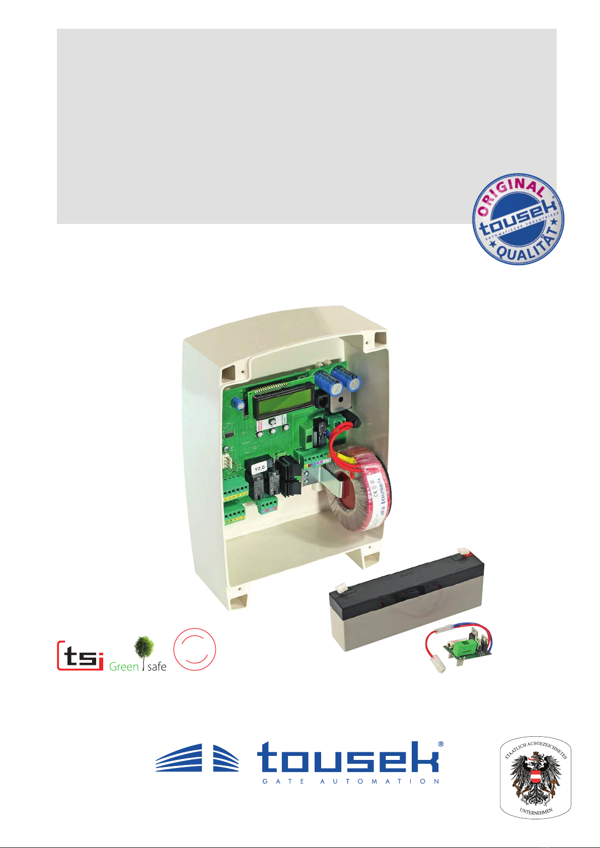
Swing gate control unit ST 12/5
optional: emergency battery and load board
b
y
T
Ü
V
-
S
ü
d
I
N
I
T
I
A
L
T
E
S
T
UNDER
EN 13241-1*)

- 2 - tousek / EN_ST-12-5_05 / 25. 03. 2020
This manual is the sole property of the TOUSEK Ges.m.b.H. and may not be made available to competitors. All rights reserved. No part of it may be reproduced without our prior
written permission. We will not accept liability for any claims resulting from misprints or errors. This edition of the manual replaces all earlier publications of the same.
Content
General warning and safety notes.......................................................................................................................... 3
1. General features, control board overview, technical data...................................................................... 4
2. Terminal assignment, connection notes ................................................................................................. 5
3. Adjustments - overview ............................................................................................................................. 6
programming keys, program menu, basic settings......................................................................... 6
menu structure................................................................................................................................ 7
4. Connections and adjustments .................................................................................................................. 8
Buttons/switches........................................................................................................................................ 8
Gimpulse switch (terminals 30/32) ................................................................................................... 8
pedestrian button (terminals 30/34)............................................................................................... 9
STOP-button (terminals 30/31)...................................................................................................... 9
Safety .......................................................................................................................................... 10
Inner and outside photocell .......................................................................................................... 10
Ginner photocell (contact: terminals 45/46)..................................................................................... 10
Gouter photocell (contact: terminals 45/48) .................................................................................... 10
Photocells - connection examples .....................................................................................11
Safety contact edges.................................................................................................................... 12
Gmain safety edge 1 (terminals 50/52) .......................................................................................... 12
Gmain safety edge 2 (terminals 50/53) .......................................................................................... 12
photocell function inside ............................................................................................................... 13
photocell function outside............................................................................................................. 13
PHC-pause time ........................................................................................................................... 13
PHC-self test ................................................................................................................................ 13
Motor connection........................................................................................................................................ 14
Left leaf .......................................................................................................................................... 15
motor left (terminals 20/21).......................................................................................................... 15
Gdelay left leaf ................................................................................................................................ 15
Gdelay time left ............................................................................................................................... 15
ARS response time....................................................................................................................... 15
max. force..................................................................................................................................... 15
soft stop time ................................................................................................................................ 15
Right leaf .......................................................................................................................................... 15
motor right (terminals 24/25) ........................................................................................................ 15
Gdelay right leaf .............................................................................................................................. 15
Gdelay time right ............................................................................................................................. 15
ARS response time....................................................................................................................... 15
max. force..................................................................................................................................... 15
soft stop time ................................................................................................................................ 15
Operating mode........................................................................................................................................ 16
impulse logic................................................................................................................................. 16
Goperating mode............................................................................................................................. 16
partial opening.............................................................................................................................. 16
automatic mode .......................................................................................................................... 16
pause time logic .......................................................................................................................... 16
closing edges (MSE 1: terminals 50/52, MSE 2: terminals 50/53................................................ 17
Lights / Lamps .......................................................................................................................................... 18
prewarning OPEN (terminals 10/11)............................................................................................. 18
prewarning CLOSE (terminals 10/11)........................................................................................... 18
courtyard lamp (add. module see page 19)................................................................................. 18
control lamp (add. module see page 19)..................................................................................... 18
Peripherals .......................................................................................................................................... 18
electric lock (terminals 72/73)...................................................................................................... 18
additional module (courtyard-/control lamp or gate status display) .............................................. 19
Diagnosis .......................................................................................................................................... 20
status display, delete position, factory setting, software version, serial number, protocol
..................... 20
5. Connection of radio receiver................................................................................................................... 21
6. Putting into operation ............................................................................................................................. 22
6.1 Connection of the backup battery (optional) ........................................................................................ 27
7. Erroy analysis .......................................................................................................................................... 28
8. Dimensioned drawing of housing IP54 .................................................................................................. 29
9. Steuerung ST 12/4 auf ST12/5 umrüsten................................................................................................ 30

tousek / EN_ST-12-5_05 / 25. 03. 2020 - 3 -
EU - Manufacturer´s Declaration:
The company TOUSEK Ges.m.b.H., based in Zetschegasse 1, A-1230 Vienna/Austria, hereby declares that the
control unit ST 12/5 complies with the folloleaf directives:
- Low Voltage Directive 2014/35/EU, incl. changes
- Electromagnetic Compatibility Directive 2014/30/EU, incl. changes
May 2019
General warning and safety notes
• These installation and operating instructions form an integral part of the product “control unit”. They have been speci-
cally written for professional installers trained and skilled in the trade and should be carefully read in their full length before
carrying out the installation. It concerns the control only, not of the overall device “automatic gate”. After the installation
this manual has to be handed over to the user.
• Installation, connection, adjustments, putting into operation, and servicing may only be carried out by trained
professionals in full accordance with these installation and operating instructions.
• Before carrying out works on the gate system, the power supply has to be turned o.
• Before taking o the housing cover, always turn o the main switch!
• The EU Machine Directive, laws and rules concerning the prevention of accidents, and laws and standards which are in
force in the EU and in the individual countries have to be strictly followed.
• The TOUSEK Ges.m.b.H. can not be held liable for any claims resulting from disregards of the laws and standards in
force during the installation and operation.
• The packaging materials (cardboard, plastic, EPS foam parts and lling material etc.) have to be properly disposed of
in accordance with the applying recycling and environmental protection laws. They may be hazardous to children and
therefore have to be stored out of children´s reach.
• The product is not suitable for installation in explosion-hazardous areas.
• The product may only be used in accordance with its original purpose, for which it has been exclusively designed, and
which is described in these installation and operating instructions. The TOUSEK Ges.m.b.H. rejects any liability if the
product is used in any way not fully conforming to its original purpose as stated herein.
• Children have to be instructed that the gate facility as well as the belonging parts may not be used improperly, e.g. for
playing. Furthermore handheld transmitters have to be kept in safe places and other impulse emitters as buttons and
switches have to be installed out of children‘s reach..
• Before beginning with the installation the installer has to make sure that all mechanical components of the gate facil-
ity, like carrier prole/rail, gate frame and panels, guiding elements etc. are suciently supportive and resistant for the
purpose of gate automation.
• All electrical installations have to be made in full conformity with the applying rules and laws (e.g. using a fault current
circuit breaker, proper grounding etc.).
• An all-pole disconnecting main switch with a contact opening-gap of minimum 3 mm has to be foreseen.
• After installation the proper function of the gate facility and the safety devices has to be checked!
• The TOUSEK Ges.m.b.H. rejects any liability for claims resulting from usage of the product in combination with compo-
nents or devices which do not fully conform to the applying safety laws and rules.
• Only original spare and replacement parts may be used for repair of the product.
• The installer has to inform the user about all aspects of the automatic operation of the complete gate facility, as well as
about emergency operation. The installer further has to supply to the user all instructions relating to the safe operation
of the gate facility. The installation and operating instructions also have to be handed over to the user.
Maintenance
• Maintenance works may only be carried out by qualied personnel.
• Maintenance and servicing of the complete gate facility has to be carried out according to the gate builder´s/
installer´s instructions.
• Check the proper sensitivity setting of the ARS safety reverse system once a month.
- 4 - tousek / EN_ST-12-5_05 / 25. 03. 2020
Text display
–
ESC ENTER
+
K
FE
F1
SV
ZM
30 31 30 32 34 50 52 53
72 73 41 42 43 44 45 46 48
20 21 24 25
0 1210 11 5 6
LPA
F2
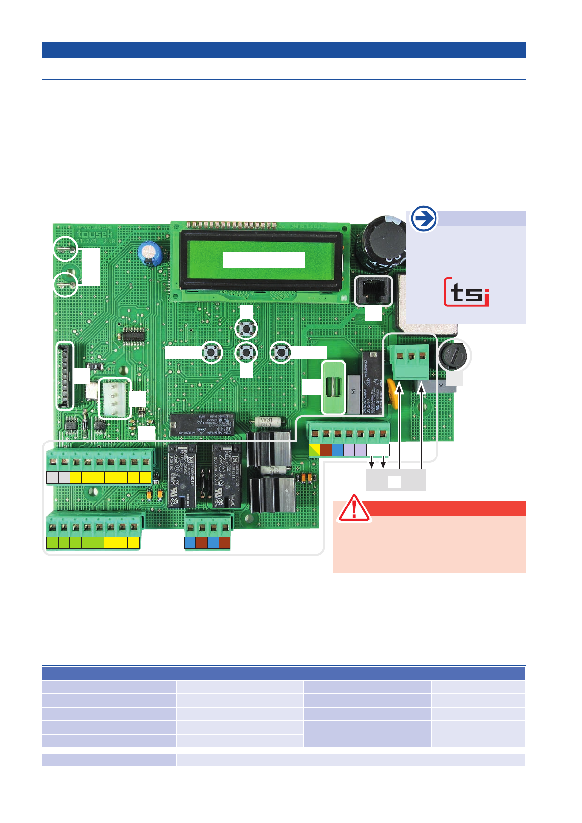
Control board features
1. General features Swing gate control unit ST 12/5
• suitable for 1/2 leafed swing gates with gate automation
SLIM-SLR and SLIM-CLR (with integrated limit switches)
• adjustable leaf delay
• ARS (Autom. reversal system - obstacle detection)
• automatic closure with adjustable pause time.
• Additional function for permanent open
• separately adjustable softstop time of both operators
• adjustable force
• Operating mode: impulse-, automatic- or deadman mode
• partial opening for pedestrians (pedestrian function)
•
direct connection for 8,2 kOhm safety edges (2-channel)
• self-monitoring of photocells
• self-diagnosis
• electric lock output
• slot for optional radio receiver and additional moudle for gate
status or for courtyard lamp/control lamp
• easy programming thanks to text display
• optional: emergency mode with battery
Technichal data
Swing gate control board ST 12/5
Power supply 230V a.c., +/-10% 50Hz Ambient temperature - 20°C bis + 50°C
Motor output 2 x 12V DC, 60W Protection class IP54
Flashing light output 230V AC, 50W max. Battery (optional) Bleigelakku 12V 2,1Ah
Electric lock output 12V DC, 15W Art.Num. 12111730
Photocell output 12V DC, 2W
Optional components pluggable receiver • backup battery • add. module for courtyard/control lamp or gate status
Components of the control board
(K) terminal blocks
(SV) service slot (e.g. for software update) or connection
with optional tousek-service-interface (TSI)
(FE) slot for optional radio receiver (p. 21)
(ZM) slot for optional additional module (p. 19)
(LPA)
loading board connection for optional emergency battery
(T) transformer
(F1) primary fuse T 2A
(F2) secondary fuse T 10A
Text display and programming keys +, -, ESC and ENTER
Attention
During connection, adjustment and main-
tenance works please take care, that the
electronic circuit board won´t be damaged by
moisture (rain).
Control board overview
Important
The optional tousek-
service-interface must be
connected with socket (SV)!
230V
a.c. T12V
a.c.

tousek / EN_ST-12-5_05 / 25. 03. 2020 - 5 -
MR
electric lock
12V DC
supply photocell
transmitter 12VDC
Vers. LS-receiver 12V DC
or accessory, max. 0,3A
common PHC
PHC-contact inside
PHC-contact outside
transmitter
receiver
12V
=
12V
=
– + – +
motor (left leaf)
motor (right leaf)
common
STOP-switch
common
IMPULSE-switch
PEDESTRIAN button
common contact safety edge
contact safety edge 1 (8,2kOhm)
contact safety edge 2 (8,2kOhm)
blue *)
brown
*)
blue *)
brown *)
30 31 30 32 34 50 52 53
72 73 41 42 43 44 45 46 48
grounding
power supply
230V a.c.
signal lamp 230V,
max. 40W
230V a.c. primary transformer
0 1210 11 5 6
ML
20 21 24 25
+ –
12V a.c. secondary transform
2. Terminal assignment Swing gate control unit ST 12/5
Warning
• Before taking o the control cover,
the main switch must be turned o !
• If an emergency battery is connected, also discon-
nect this battery!
• The inside of the control unit is under tension when
power supplied.
• In order to avoid electrical strokes, the safety regula-
tions have to be respected.
• The device may only be connected by qualied per-
sonnel (specialised sta).
• The product is not suitable for installation in explosion-
hazardous/explosive areas.
• An all-pole disconnecting main switch with a contact
opening gap of min. 3 mm has to be foreseen. The
gate facility has to be secured according to the valid
safety regulations!
• IMPORTANT: The control lines (sensor, buttons, radio,
photocells, etc.) have to be laid separately from the
230V lines (supply line, motors, signal lamp).
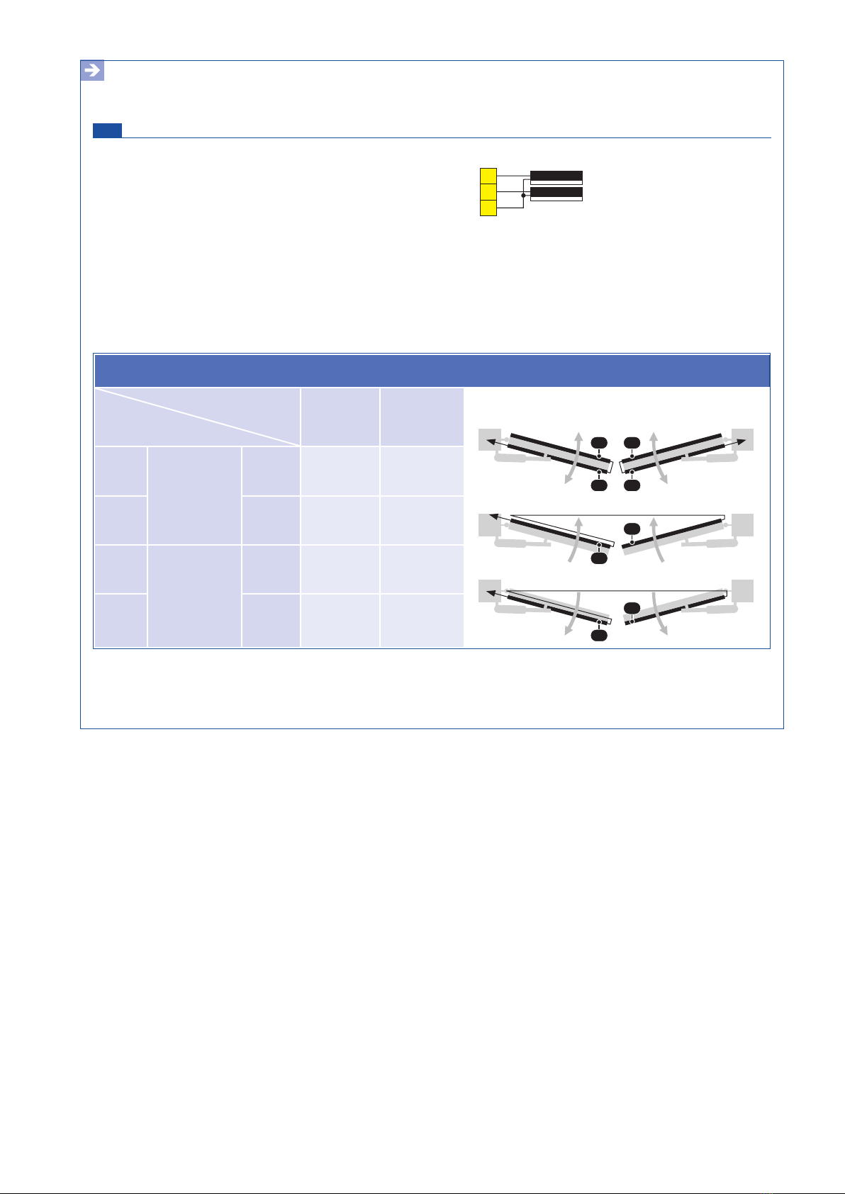
When connecting the operators to the control unit, always pay attention
to the door situation, ie whether the door opens inwards or outwards
(= special case). The drive connection (see table) and the function of the
limit switches (see operator manual) are dependent on this.
Door situation *) opening inwards
special case:
opening outwards
Motor LEFT RIGHT LEFT RIGHT
blue cable to terminal: 20 24 21 25
brown cable to terminal: 21 25 20 24
Special case: opening outwards
left operator INSIDE right operator
left operator INSIDE right operator
*) opening inwards
The stop input has no emergency stop function! - In order to ensure the emergency stop function, provide
the supply line with an all-pole disconnecting emergency stop switch, that locks after actuation!
- 6 - tousek / EN_ST-12-5_05 / 25. 03. 2020
–
ESC ENTER
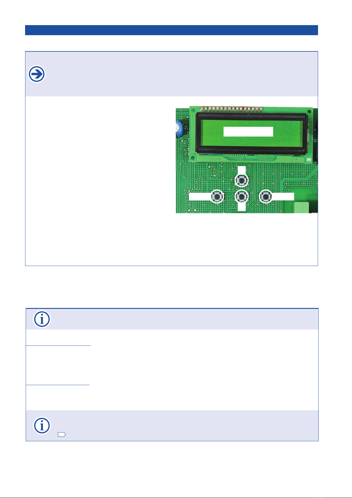
+
Text display
• The programming menu is divided into „BASIC SETTINGS“ and the „MENU CONTROL“ (MAIN MENU)
BASIC SETTINGS
• When programming the control the rst time, you enter the „BASIC SETTINGS“.
• Here the necessary adjustments for operation of the gate facility are made.
• Entering the menu control (for extended programming) is possible by selecting „MENU CONTROL“.
MENU CONTROL
• The next time you will directly enter „MENU CONTROL“. (The BASIC SETTINGS are skipped.)
• The menu control contains all possible adjustments.
In the following the single menu points are marked as shown below:
= possible adjustment (or value assignment) = factory setting = status display
Gmarks the menu points which are contained in the BASIC SETTINGS.
Programming keys Adjustments - Overview
• The adjustment (programming) of the operating parameters is carried out via four programming buttons and
the text display.
• Before you can start programming, select the language of the display. You can do this by pressing the + or -
and choose the language for the menuas and press ENTER.
• Note: The language setting can be changed any time by pressing the ESC button for 5s.
• The text display informs you on the operating modes,
selected menus and adjustment of several parameters.
• The programming of the control is done through four but-
tons (+, -, ENTER and ESC).
• Scrolling through the different menu points (up/
down) and changing a parameter (increase/
decrease) is done with buttons + and - .
AUTO-COUNT: When a button is pressed and held, an
automatic scrolling of the menu (or change of the param-
eter) is carried out.
• By pressing the ENTER-button you enter the displayed
menu point or memorise the shown value of a parameter.
• By pressing the ESC-button you return to the superior
menu point. Changed adjustments of a parameter are
rejected with this button (the original value is kept).
• AUTO-EXIT: If during programming no button is actu-
ated for 1 minute or longer, the programming mode is left
automatically. The control is set „ready“ without storage
of possibly changed values.
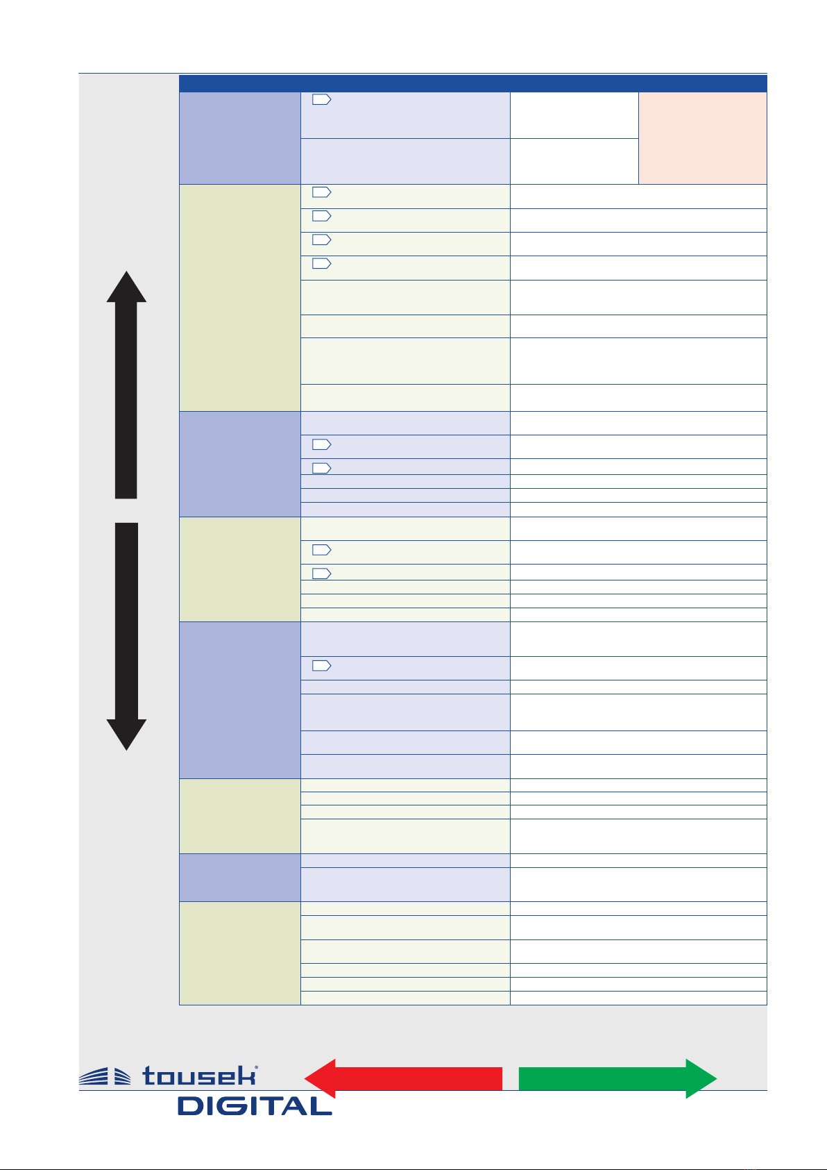
Programming menu Adjustments - Overview
3. Adjustments - overview Swing gate control unit ST 12/5
tousek / EN_ST-12-5_05 / 25. 03. 2020 - 7 -
Main layer Sub layer Adjustments
buttons/switches
see page 8
Gimpulse button OPEN/STOP/CLOSE
OPEN/CLOSE/OPEN
OPEN
DEAD MAN
*) if impulse button is
set to DEADMAN, then
the pedestrian and
close button are also
set automatically to
DEADMAN mode.
(not selectable under
„pedest.- button“)
pedestrian button OPEN/STOP/CLOSE
OPEN/CLOSE/OPEN
OPEN
DEAD MAN *)
safety
see page 10
Ginner photocell active
not active
Gouter photocell active
not active
Gmain safety edge 1 active
not active
Gmain safety edge 2 active
not active
photocell function inside during closing reverse
stop - after release open
during opening stop - then open
photocell function outside during closing reverse
stop - after release open
PHC-pause time no inuence of photocell
abort pause time
re-start of pause time
immediate close after opening
PHC-self test active
not active
left leaf
see page 15
motor left motor ON
motor OFF
Gdelay left leaf opening delay
closing delay
Gdelay time left 0...25s = 2s
ARS response time 0,15...0,95s = 0,70s
max. force 30...100% = 70%
soft stop time 0...25s = 5s
right leaf
see page 15
motor right motor ON
motor OFF
Gdelay right leaf opening delay
closing delay
Gdelay time right 0...25s = 2s
ARS response time 0,15...0,95s = 0,70s
max. force 30...100% = 70%
soft stop time 0...25s = 5s
operating mode
see page 16
impulse logic stop, start of pause time
impulse suppression when opening
pause time extension
Goperating mode impulse mode
automatic 1...255s
partial opening 25...100% = 100%
automatic mode complete/partial opening
only complete opening
only partial opening
pause time logic no inuence
permanent open in automatic mode
closing edges left/right
inside/outside
lights/lamps
see page 18
prewarning OPEN OFF, 1...30s = OFF
prewarning CLOSE OFF, 1...30s = OFF
courtyard lamp 1OFF, 5...950s = OFF
control lamp 1illuminates during open and close
blinks slowly/illuminates/blinks
illuminates in open position
peripherals
see page 18
electrick lock OFF, 1...10s = OFF
additional module courtyard lamp/control lamp
status display 1
status display 2
diagnosis
see page 20
status display status display
delete position NO
YES
factory setting NO
YES
software version shows software version
serial number shows serial number
protocol shows protocole inputs
1) the menu items courtyard lamp and control lamp will only appear on display, if under
additional module courtyard/control lamp is selected.
Swing gate control ST12/5
+
–
Menu structure Adjustments - overview
ESC ENTER
Note: Some changes in the functioning or operation logic are accepted only when the gate is closed and the „Ready“ appears on the display.
- 8 - tousek / EN_ST-12-5_05 / 25. 03. 2020
Push buttons, key switches or external radio receivers with potential-free make contacts can be used as impulse
switches.
Warning
• Before taking o the control cover,
the main switch must be turned o !
• If an emergency battery is connected, also discon-
nect this battery!
• The inside of the control unit is under tension when
power supplied.
• In order to avoid electrical strokes, the safety regula-
tions have to be respected.
• The device may only be connected by qualied
personnel (specialised sta).
• The product is not suitable for installation in explosion-
hazardous/explosive areas.
• An all-pole disconnecting main switch with a contact
opening gap of min. 3 mm has to be foreseen. The
gate facility has to be secured according to the valid
safety regulations!
• IMPORTANT: The control lines (sensor, buttons, radio,
photocells, etc.) have to be laid separately from the
230V lines (supply line, motors, signal lamp).
• A general status display of all inputs is available in menu DIAGNOSIS/STATUS DISPLAY.
GImpulse button (terminals 30/32) Buttons/switches
OPEN/STOP/CLOSE successive impulses (factory setting):
An impulse of the impulse switch makes the motor start opening/closing. If the impulse switch is actuated again during this
opening-/closing movement, the motor stops. With the next command of the impulse switch the motor moves in the opposite
direction of the last gate movement.
OPEN/CLOSE/OPEN successive impulses: an impulse of the impulse switch makes the motor start opening/closing.
If the impulse switch is actuated again during this opening/closing movement, the travel direction is reversed.
•In this operation mode it is not possible to stop the motor with the impulse switch – it always
moves until reaching an end position. (Opened or closed position).
• for the function OPEN/CLOSE/OPEN we strongly suggest the installation of a photocell!
OPEN: Only opening commands are accepted by the impulse switch – closing the gate with the impulse switch is not
possible.
DEAD MAN: The motor opens as long as the impulse switch is pressed (hold) – closing the gate with the impulse switch
is not possible. As soon as the switch is released, the motor stops. If dead man‘s operation (=hold to run) is chosen,
the radio receiver is out of order for reasons of safety.
• If the impulse switch is set to DEAD MAN operation, then the pedestrian button works
the same way. With the impulse switch the gate is opened, with the pedestrian button it is closed.
• IMPORTANT: Do not put into operation in dead man mode.
Select only after putting into operation (see page 22), if desired.
Buttons/switches Connections and adjustments
4. Connections and adjustments Swing gate control unit ST 12/5
The single menu points are marked as shown below:
= possible adjustment (or value assignment) = factory setting = status display
Gmarks the menu points which are contained in the BASIC SETTINGS.

tousek / EN_ST-12-5_05 / 25. 03. 2020 - 9 -
Push buttons, key switches or external radio receivers with potential-free make contacts can be used as pedestrian
button.
Pedestrian button (terminals 30/34) Buttons/switches
OPEN/STOP/CLOSE successive impulses: An impulse through the pedestrian button-while the gate is in motion-
causes gate stopping. If the gate is within the pedestrian area, then an impulse through the pedestrian button causes
inversion of the direction.
If the gate is in complete open position an impulse through the pedestrian button causes a movement in CLOSE direc-
tion and the gate stopps at pedestrian OPEN position.
OPEN/CLOSE/OPEN successive impulses:
If the gate is within the pedestrian area, then an impulse through the pedestrian button causes inversion of the direction.
If the gate is in complete open position an impulse through the pedestrian button causes a movement in CLOSE direction
and the gate stopps at pedestrian OPEN position.
•In this operation mode it is not possible to stop the motor with the pedestrian button – it always
moves until reaching an end position. (Opened or closed position).
• for the function OPEN/CLOSE/OPEN we strongly suggest the installation of a photocell! !
OPEN: Only opening commands are accepted by the impulse switch – closing the gate with the impulse switch is not
possible.
DEADMAN: The motor opens as long as the impulse switch is pressed (hold) – closing the gate with the impulse switch
is not possible. As soon as the switch is released, the motor stops.
As soon as the deadman function is activated, the radio receiver is without function (due to safety reasons).
The DEADMAN function can not be chosen actively but is set automatically as soon as the impulse
button is set to DEADMAN mode.
STOP-switch (terminals 30/31) Buttons / switches
• when pressing the stop switch the gate stops in any desired position.
As stop switch a break contact has to be used.
If no stop switch is connected, terminals 30/31 have to be wire-bridged.
31
30
The stop input has no emergency stop function! - In order to ensure the emergency stop function, provide
the supply line with an all-pole disconnecting emergency stop switch, that locks after actuation!
- 10 - tousek / EN_ST-12-5_05 / 25. 03. 2020
Important: notes for photocells
• The control unit has a power supply connection for 12V DC photocells (LS):
Power supply LS-transmitter: terminals 41(-) / 42(+), Versorgung LS-receiver: terminals 43(-) / 44(+)
Hinweis: Kl. 41/42 werden in der „Tor geschlossen“- Stellung in den Stromsparmodus (d.h. spannungsfrei)
geschalten.
• At supplied and positioned photocells the contact has to be closed (make contact).
Connection of outer photocell contact: terminals 45/48, inner photocell contact terminals 45/46
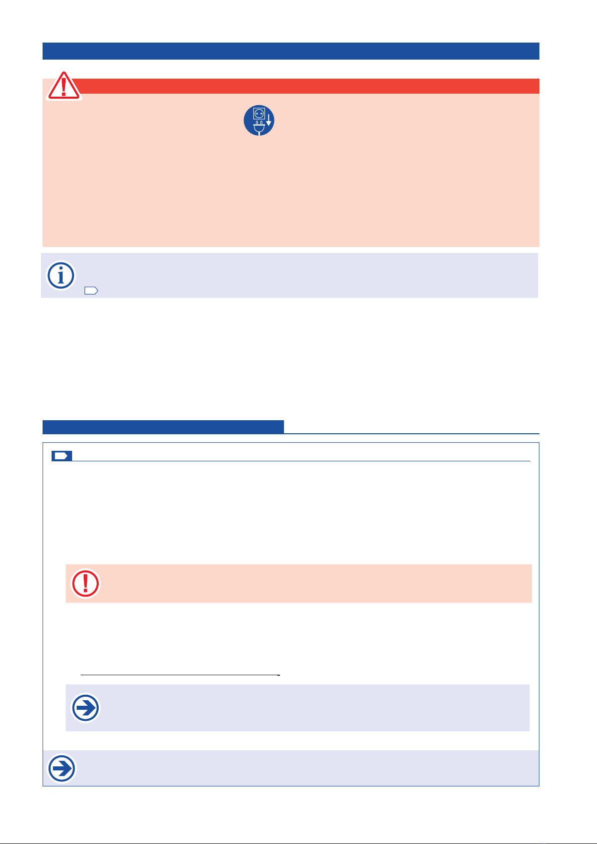
• When using two pairs of photocells please do not
install both photocell transmitters/receivers on the
same side (to eleminate interference between both) !
•
Self-monitoring of photocells: The control unit has a monitoring function for the connected photocells. A test will be
triggered by each ipumlse and will be checked if the receiver of the photocell responds to the signal from the photocell
transmitter.
If there is no communication between the photocell receiver and transmitter the control unit responds with an error.
The deactivation of the self-test function is only permitted if the safety installations correspond to the
category 3 !
• The exact function of the photocells depends on the programming of the control unit.
Photocell functions see menu point SAFETY/inner (outer) photocell function, resp. photocell with pause time
(page 13).
• Detailed information you will nd in the corresponding photocell manual.
Standard:
transmitter 1 receiver 1
receiver 2 transmitter 2
INNER AND OUTER PHOTOCELL Safety
inner photocell
outer photocell
INSIDE
• Energy saving mode:photocell transmitter is turned
o when gate is closed
• With additional inner photocells the back area of
the gate can be monitored. (All inner photocells are
then set in series at control terminals 45/46 (terminals
for inner photocells))..
• The exact function of the photocells depends on the
programming of the control unit:
Photocell functions see page 13.
inner photocell for monitoring of
gate back rear (left)
inner photocell for monitoring of
gate back rea (right)
GInner photocell (contact: terminals 45/46) Safety
active: to be selected, if inner photocell should be triggered.
not active: to be selected, if inner photocell should not be triggered.
Safety Connections and adjustments
GOuter photocell (contact: terminals 45/48) Safety
active: to be selected, if outer photocell should be triggered.
not active: to be selected, if outer photocell should not be triggered.

tousek / EN_ST-12-5_05 / 25. 03. 2020 - 11 -
Deactivation of SYNC-Function
• The SYNC-Function of LS41 is not pos-
sible with this control board.For deacti-
vation the jumpers have to be placed
in both LS-transmitters (pict. right).
see also manual of LS 41.
SYNC
J
Outer photocell
Tousek LS 41 as safety device
Outer and inner photocell
Tousek LS 41 as safety device
transmitter receiver
receiver transmitter
OUTSIDE:
INSIDE:
transmitter receiver
Photocells - connection examples
Important
• Jumper J of transmitter and receiver has to be
adjusted in the same way.
Outer photocell
Tousek LS 26 as safety device
Outer reective photocell
Tousek RLS 620
as safety device
transmitter receiver
48
45
44
43
42
41
46
+
~
-
~
12/24V
J
+
~
-
~
12/24V
NC C NO
J
+
–
+
–
+
–
48
45
42
41
46
44
43
12V DC
12–240V
AC/DC
NO
NC
COM
COM
N.O.
COM
N.C.
+
–
+
–
N.O.
COM
N.C.
N.O.
COM
N.C.
+
–
+
–

- 12 - tousek / EN_ST-12-5_05 / 25. 03. 2020
Important (for programming)
• IMPORTANT: during programming of motor the contact safety edges should not be triggered as this leads to
an error message - the limit stops have to be placed correspondingly.
SAFETY SENSING EDGES Safety
GMain safety edge 1 (terminals 50/52) Safety
active: to be selected if the contact strip (8,2kOhm) of main safety sensing edge 1 should be evaluated.
not active: to be selected if the contact strip of main safety sensing edge 1 should not be evaluated
GMain safety edge 2 (terminals 50/53) Safety
active: to be selected if the contact strip (8,2kOhm) of main safety sensing edge 2 should be evaluated.
not active: to be selected if the contact strip of main safety sensing edge 2 should not be evaluated.
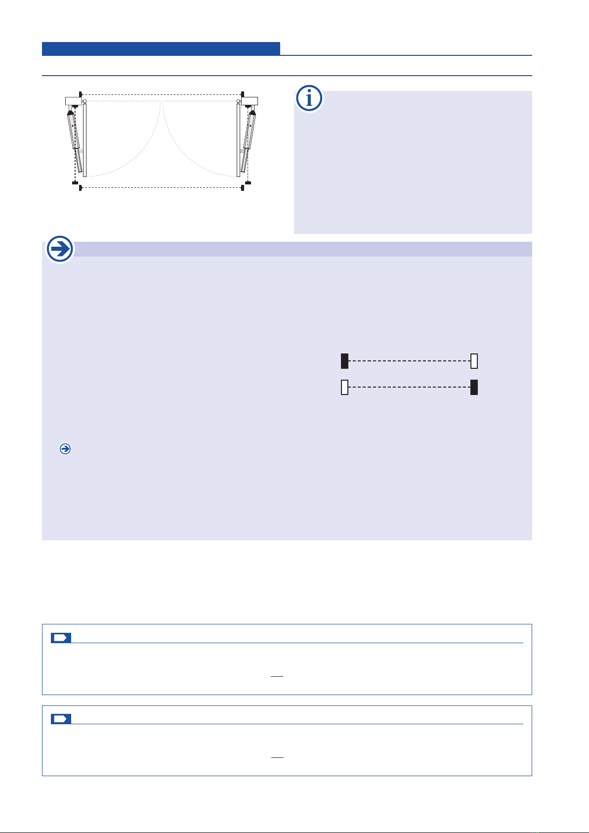
Safety sensing edges (main closing edge 1 + 2)
• OBSTACLE DETECTION: when a contact strip/safety edge is triggered/activated then a change of direction is
eected for 1 second. Then the gate stops.
• The activation of the safety sensing edges is made in menu „Safety / main closing edge 1“ (term. 50/52) and
„Safety / main closing edge 2“ (term. 50/53)
• If in the menu item „operating logic / closing edge“ (see
page 16,17) one of the modes „left / right“ or „inside /
outside“ is selected - consequently there is the wiring
of the contact strips with each other and the connection
to the control terminals.
Safety sensing edges in mode „left/right“, that should react on an obstacle at the left (right) leaf, have to
be connected (serially) to the connection clamps of the main closing edge 1 (2).
Safety sensing edges in mode
„inside/outside“, which should react
on an obstacle at the inner
(outer)
side of the leaf,
be connected (serially) to the connection clamps of the main closing edge 1 (2).
Example: W 8,2kΩ nal resistance
E nal edge
D passage edge
S to the control board
When connecting one safety edge a nal edge (E) has to be used.
Main safety edge 2
(right leaf or outside)
Main safety edge 1
(left leaf or inside)
8,2kOhm
8,2kOhm
53
52
50
HSK 2
HSK 1
E
W
D D S
50
52
50
53
main safety edge 1
main safety edge 2
tousek / EN_ST-12-5_05 / 25. 03. 2020 - 13 -
Photocell function inside Safety
during closing reverse: an interruption of the photocell during closing makes the gate reverse (open). In automatic
mode the gate closes as soon as the pause time has run out. In impulse operation another closing command has to
be given.
stop - after release open: an interruption of the photocell beam during opening or closing makes the motor stop as
long as the photocell stays interrupted. After release of the photocell, the gate opens. In automatic mode the gate closes
as soon as the pause time has run out, in impulse operation another closing command has to be given.
during opening stop - then open: an interruption of the photocell during opening makes the motor stop as long as
the photocell stays interrupted. After release of the photocell, the gate opens (back area monitoring). In automatic mode
the gate closes as soon as the pause time has run out, in impulse operation another closing command has to be given.
Photocell function outside Safety
during closing reverse: an interruption of the photocell during closing makes the gate reverse (open). In automatic
mode the gate closes as soon as the pause time has run out. In impulse operation another closing command has to
be given.
stop - after release open: an interruption of the photocell beam during opening or closing makes the motor stop as
long as the photocell stays interrupted. After release of the photocell, the gate opens. In automatic mode the gate closes
as soon as the pause time has run out, in impulse operation another closing command has to be given
PHC-pause time Safety
no inuence of photocell: the photocell doesn’t have any inuence on the pause time in automatic mode.
abort pause time: in automatic mode an interruption of the photocell during pause time shortens the pause time. After
release of the photocell the gate starts closing.
re-start of pause time: in automatic mode an interruption of the outer photocell during pause time, restarts the pause
time. As soon as the pause time has run out, the gate closes.
immediate close after opening: If the photocell is interrupted during the opening movement, the gate starts closing
as soon as it reached end position open after release of the photocell.
PHC-self test Safety
active: photocell self-test is executed with an opening impulse (switch, button) in gate position „closed“.
not active: photocell self-test is not executed
Attention
• The photocell self-test can only be deactivated by selecting „not active“.
• The deactivation of the self-test function is only permitted if the safety installations correspond to the
category 3 !
PHOTOCELL FUNCTIONS Safety
- 14 - tousek / EN_ST-12-5_05 / 25. 03. 2020
Warning
• Before taking o the housing cover the
main switch has to be turned o !
• IMPORTANT: At force adjustment (see Left(Right)
wing) the valid safety regulations and standards
have to be strictly followed!
• Follow safety instructions (see page 8) !
CONNECTION OF MOTORS
MR
motor (left leaf)
motor (right leaf)
blue *)
brown
*)
blue *)
brown *)
ML
20 21 24 25
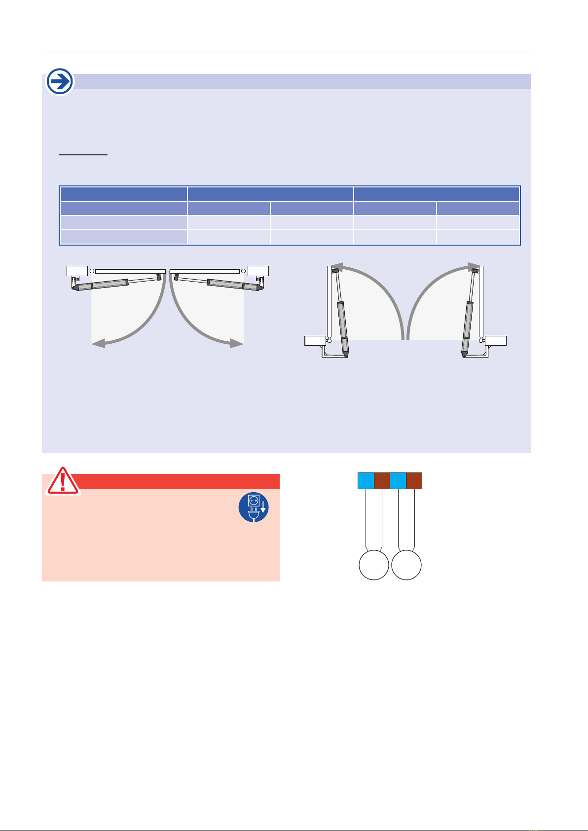
Important: notes for connection and adjustment of operators
• It is possible to connect 2 motors 12V DC, max. 60 W to the control board ST 12/5.
Motor left: terminals 20/21 / Motor right: terminals 24/25
• Attention: Before carrying out any installation and connection works, the power supply of the gate facility has
to be turned o!
• Connection:
When connecting the operators to the control unit, always pay attention to the door situation, ie
whether the door opens inwards or outwards (= special case). The drive connection (see table) and the function
of the limit switches (see operator manual) are dependent on this.
Door situation *) opening inwards special case: opening outwards
Motor LEFT RIGHT LEFT RIGHT
blue cable to terminal: 20 24 21 25
brown cable to terminal: 21 25 20 24
left motor INSIDE right motor
special case: opening outwards
left motor right motor
INSIDE
*) opening inwards
• IMPORTANT:At operation with a single motor, the other motor input has to be deactivated by choosing
„MOTOR OFF“. If the LEFT (RIGHT) wing is set to OFF in the menu, no motor may be connected with the
concerned wing.
• OBSTACLE DETECTION: If a gate wing runs into an obstacle a change of direction is eected for 1 second.
Then the gate stops.

tousek / EN_ST-12-5_05 / 25. 03. 2020 - 15 -
INSIDE
motor left (terminals 20/21) Left leaf
motor ON
motor OFF
Gdelay left leaf Linker Flügel
opening delay: The leaf opens against the right one only after a set delay time.
closing delay: The leaf closes against the right one only after a set delay time.
Gdelay time left 2s (factory setting) Left leaf
0–25s delay time adjustable: denes the delay during opening or closing.
ARS response time 0,70s (factory setting) Left leaf
0,15–0,95s ARS response time adjustable: denes, in what time the AR-system responds. The lower the value the
more sensitive the system is set.
max. force 70% (factory setting) Left leaf
30–100% adjustable: determines the motor force
soft stop time 5s (factory setting) Left leaf
0–25s adjustable: denes the duration of soft stop phase.
left motor
INSIDE
Left leaf Connections and adjustments
right motor
Important
• the adjustment has to match the actual situation of
the motor connection !
motor right (terminals 24/25) Right leaf
motor ON
motor OFF
Gdelay right leaf Linker Flügel
opening delay: The leaf opens against the left one only after a set delay time.
closing delay: The leaf closes against the left one only after a set delay time..
Gdelay time right 2s (factory setting) Right leaf
0–25s delay time adjustable: denes the delay during opening or closing.
ARS response time 0,70s (factory setting) Right leaf
0,15–0,95s ARS response time adjustable: denes, in what time the AR-system responds. The lower the value the
more sensitive the system is set.
max. force 70% (factory setting) Right leaf
30–100% adjustable: determines the motor force
soft stop time 5s (factory setting) Right leaf
0–25s adjustable: denes the duration of soft stop phase.
Right leaf Connections and adjustments
Important
• the adjustment has to match the actual situation of
the motor connection !

- 16 - tousek / EN_ST-12-5_05 / 25. 03. 2020
Impulse logic Operating mode
stop, start of pause time: a command of the impulse switch during the opening movement stops the gate and starts
the pause time in automatic operation – as soon as the pause time has run out, the gate closes automatically.
impulse suppression when opening: commands which are emitted during the opening movement are suppressed.
Commands during closing are accepted.
pause time extension: an impulse in automatic operation restarts the pause time. If this menu point is chosen, the
impulse suppression during opening is active at the same time.
GOperating mode Operating mode
impulse mode: for initiating the closing movement, an impulse is necessary.
automatic closing, pause time adjustable from 1-255s: gate closes as soon as the adjusted pause time has run out
(Exception: see adjustment „Automatic mode“ / „only complete opening“).
Partial opening 100% (factory setting) Operating mode
25–100% adjustable: indicates the partial opening of the gate leaf with closing delay in relation to complete opening
width.
This adjustment is ONLY adopted in CLOSED Postion.
Automatic mode Operating mode
complete/partial opening: either with complete as well as partial opening, the gate closes automatically after the
adjusted pause time.
only complete opening: only after complete opening, the gate closes automatically after the adjusted pause time.
Exception: If the gate is in partial open position and an impulse for complete opening arrives then the gate opens
completely and after the pause time it returns to partial opening position.
only partial opening: only after partial opening the gate closes automatically after the the adjusted pause time.
Pause time logic Operating mode
no inuence
permanent open in automatic mode: If „always open in automatic mode“ and „pause time“ are simultaneaus activated
the automatic mode can be deactivated. An impulse in complete open position causes a switch into „impulse mode“
but only for hte current cycle. So the gate stays in OPEN position. The next impulse closes the gate an the control unit
switched to „automaitc mode“ again. This function allows that the entrance of a company site stays open during the day
(rst impulse in complete open position). The gate can be closed with the second impulse e.g. in the evening (second
impulse - for closing the gate and switching to the „automatic mode“). The control unit switches to the „automatic mode“
again (automatic opening and closing of the gate).
Note: An impulse through the pedestrian button in the complete open position doesn´t start the „always open“ function.
This action causes a movement in CLOSE direction and the gate stopps at pedestrian OPEN position.
If the gate is in partial open position and „permanent open in automatic mode“ is selected, so it is possible to adjust
permanent partial open for this cycle by giving an impulse via pedestrian button. Permanent partial open can be nished
analogous to the above described method.
Operating mode Connections and adjustments
tousek / EN_ST-12-5_05 / 25. 03. 2020 - 17 -
Main safety edge 2
(right leaf or outside)
Main safety edge 1
(left leaf or inside)
8,2kOhm
8,2kOhm
53
52
50
HSK 2
HSK 1
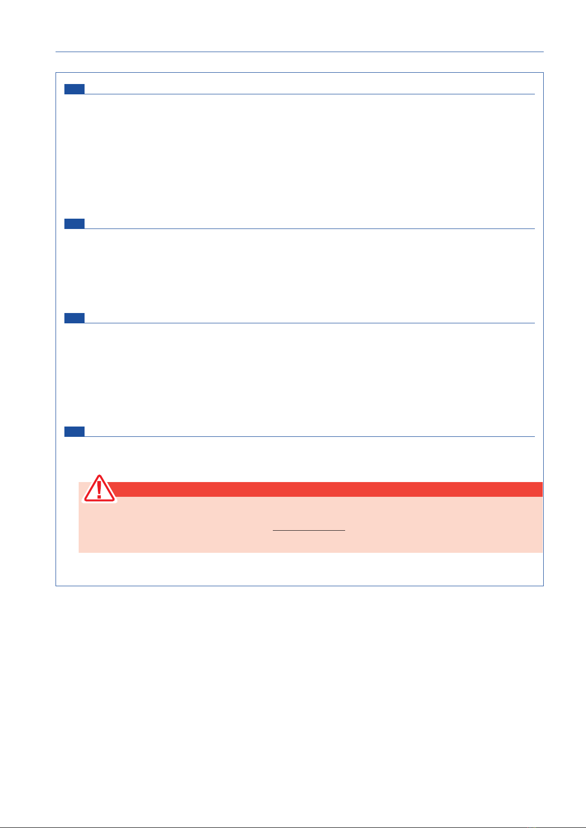
Closing edges (HSK 1: terminals 50/52, HSK 2: terminals 50/53) Operating logic
left/right: the safety sensing edges (contact strips) can
actuate in every gate movement (OPEN/CLOSE).
Contact edges that should react on an obstacle on the
left leaf (in serial connect.) should be connected on the
terminals of the main safety edge 1: term. 50/52.
Contact edges that should react on an obstacle on the right leaf (in serial connect.) should be connected on the ter-
minals of the main safety edge 2: term. 50/53. .
inside/outside:
Contact edges that should react on an obstacle at the inside of the leaf during opening, must be connected
(serial) on the terminals of the main safety edge 1: term. 50/52.
Contact edges that should react on an obstacle at the outside of the leaf during closing, must be connected
(serial) on the terminals of the main safety edge 2: term. 50/53
IMPORTANT ! ASSIGNMENT AND RESPONSE OF SAFETY EDGES
movement
Assignment
opening closing Examples: (D) passage edge, (E) nal edge
left (HSK 1 - Kl.50/52) right (HSK 2 - Kl.50/53)
D
E
D
E
outside (HSK 2-Kl.50/53)
D
E
inside (HSK 1-Kl.50/52)
D
E
HSK 1
mode
left/right
left active active
HSK 2 right active active
HSK 1
Modus
inside/outside
inside active
HSK 2 outside active

- 18 - tousek / EN_ST-12-5_05 / 25. 03. 2020
Important: Notes regarding
connection of a ashing light
• Attention: Before carrying out
connection works, the power
supply of the facility has to be
turned o.
• A ashing light with 230V, max.
40W can be connected at the
terminals 10/11
11
10
2
1
0
The following two menu points can only be selected if the menu point additional menu is adjusted to „Courtyard-/Control
lamp“ (hence shown on display).
Courtyard lamp (Description add. modules page 19)Lights / Lamps
switched o
5–950 adjustable: at the courtyard lamp output an external lamp can be connected (e.g. garden lamp), which can be
turned on for each opening command for the duration of adjusted time.
Control lamp (Description add. modules page 19) Lights / Lamps
illuminates during open and close: The pilot lamp output is activated during opening- and closing movement.
blinks slowly/illuminates/blinks: The pilot lamp output is activated as follows: During opening the pilot lamp ashes
slowly. During pause time, in opened position or when the gate stops it is illuminated. During the closing movement
it ashes rapidly. If the gate is closed, the pilot lamp expires
illuminates in open position: Pilot lamp is illuminated as soon as the gate has reached end position open.
• Before taking o the housing cover the
main switch has to be turned o !
• Follow safety instructions (see page 8) !
Warning
Prewarning OPEN (terminals 10/11) Lights / Lamps
switched o
1–30s adjustable: before each opening movement the ashing light is activated for the adjusted time.
Prewarning CLOSE (terminals 10/11) Lights / Lamps
switched o
1–30s adjustable: before each closing movement the ashing light is activated for the adjusted time.
Lights / Lamps Connections and adjustments
• Before taking o the housing cover the
main switch has to be turned o !• Follow safety instructions (see page 8) !
Warning
Peripherals Connections and adjustments
Electric lock
• To terminals 72/73, an e-lock 12V
DC, max. 15W can be connected.
• Only electric locks that are
designed for 12V DC, can be
connected.
12V DC, max. 15W
72 73
Electric lock (terminals 72/73) Peripherals
switched o
1–10s adjustable: The electric lock is activated by
push button impulse or impulse from pedestrian button
for a period of time set here to ensure the release
depending on the gate situation
+ –
tousek / EN_ST-12-5_05 / 25. 03. 2020 - 19 -
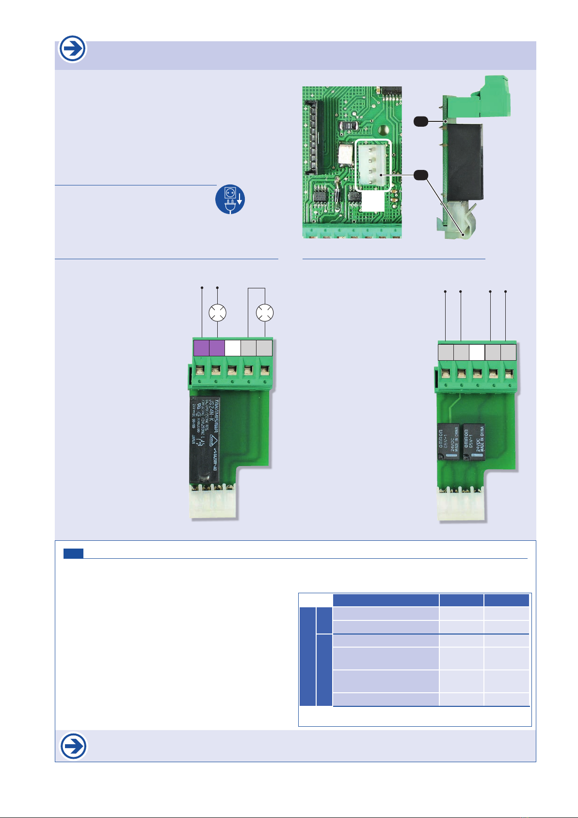
Additional module
Courtyard lamp/control lamp hence gate status display
• The use of one of the addtional modules is optional.
• Depending on which device, e.g. a courtyard-/Control
lamp is chosen or evaluation of gate status should be
eected, the corresponding module has to be plugged to
the according slot/plug of control board.
• Additionally the corresponding value has to be selected
in menu point „Additional module“.
Connecting an additional module
• turn o power supply !!
• Plug additional module (Z) through
opening onto the slot (ZM).
Additional module Courtyard lamp/Control lamp
• On the terminals 12/13
a courtyard lamp (H)
can be connected: 230V,
max. 100W
• On the terminals 70/71
a control lamp (K) can
be connected: 12V d.c.,
max. 2W
L N
1213 7071
H K
– +
Additional module Gate status display
• with potential free signal
contacts K1 (Kl. 90/91)
and K2 (Kl. 92/93) the
gate staturs can be eva-
luated in two ways (see
menu point „Additional
module“).
• Contact load:
24V a.c./d.c., max. 10W 90 91 92 93
Signal contact K1
Signal contact K2
Requirement for the realization of one of the selected options (courtyard-/control lamp or door status 1
or 2, is the presence of the corresponding supplementary module.
Additional module Peripherals
Courtyard lamp/control lamp: the menu points courtyard lamp and control lamp are ready for adjustment a(that means
if not selected, these menu points will not be shown on the display)
status display 1: with the two potential-free signal
contacts K1 and K2, the gate end positions (limits) can be
evaluated.
status display 2: with the two potential-free signal
contacts K1 and K2, the gate end positions (limits) as well as
direction of gate movement can be evaluated.
function K1 K2
gate status display
1gate in CLOSE-position 1 0
gate in OPEN-position 0 1
2
gate in CLOSE-position 1 1
gate opens, or has been
stopped 1 0
gate closes, or has been
stopped 0 1
gate in OPEN-position 0 0
0 = Signal contact open, 1= Signal contact closed
ZM
Z
ZM

- 20 - tousek / EN_ST-12-5_05 / 25. 03. 2020
Note: The factory settings of the
single menu points are marked
with in this manual.
Status display Diagnosis
Status display for inputs as photocell, safety sensing edges, stop button, impulse switch....
I impulse switch
P partial opening switch
CCLOSE-switch
SSTOP-switch
Pi photocell inside
Po photocell outside
1safety edge main closing edge 1
2safety edge main closing edge 2
Delete position Diagnosis
NO: does not delete the end positions “gate closed”
and “gate open”
YES: the determined end positions are beeing deleted.
Note: the end positions will be determined after new impulse.
factory setting Diagnosis
NO: no reset back to factory settings
YES: reset back to factory settings
Software version Diagnosis
shows the software version on display
Serial number Diagnosis
shows the serial number on the display screen
Protocol Diagnosis
shows the protocol list on display: all events that take place are protocolled in this list.
with the buttons +and -the single events can be seen:
All inputs OK.
e.g.
Diagnosis Connections and adjustments
$$$$$$$$$$$$$$$$
$$$$$$$$$$$$$$$$
T -00 00:00:00.0
Event
With * the protocole beginning
hence the end is shown
Type of event
Time since the last event:
DAYS HOURS : MINUTES : SECONDS
$$$$$$$$$$$$$$$$
$$$$$$$$$$$$$$$$
I P C S Pi Po 12 $$$$$$$$$$$$$$$$
$$$$$$$$$$$$$$$$
I P C S Pi Po 12
- - x-
The mechanical stops have to be placed so
that possibly existing safety contact edges
can not be triggered, as this would lead to
an error message.
Impulse-, pedestrian - and close button not triggered.
STOP-button and photocell inside are triggered.
Photocell outside is not triggered.
Contact strip 1 not connected or defect.
Contact strip 2 is triggered.
$Status: not triggered
$-Status: triggered
$xStatus: contact strip not connected or defect
$oStatus: contact strip or photocell deactivated in menu
Table of contents
Other tousek Garage Door Opener manuals


Popular Garage Door Opener manuals by other brands


Nice
Nice SN6031 Instructions and warnings for the fitter

Aperto
Aperto 868 Installation and operating instructions

Forematic
Forematic F350 installation manual

Roger Technology
Roger Technology BH30/603/115V INSTRUCTIONS AND RECOMMENDATIONS FOR THE INSTALLER

Chamberlain
Chamberlain HandyLift Deluxe CR650EVO Installation and operating instructions

Chamberlain
Chamberlain Security+ 6200-2K owner's manual


