tousek GTZ-Digital Series User manual

Mounting and installation manual
Garage door opener GTZ-Digital

- 2 - tousek / EN_GTZ-Digital_07 / 10. 10. 2019
This manual is the sole property of the TOUSEK Ges.m.b.H. and may not be made available to competitors. All rights reserved. No part of it may be reproduced without our prior
written permission. We will not accept liability for any claims resulting from misprints or errors. This edition of the manual replaces all earlier publications of the same.
Index
About this document......................................................................................................................................... 4
Explanation of symbols .................................................................................................................................... 3
1. General safety information............................................................................................................................ 4
1.1 intended use............................................................................................................................................... 4
1.2 Target group .............................................................................................................................................. 4
1.3 Warranty .................................................................................................................................................... 4
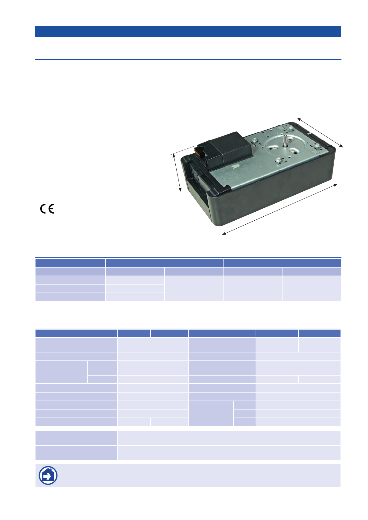
General features, application, technical Details.......................................................................................... 5
2. Scope of delivery............................................................................................................................................ 6
3. Door system.................................................................................................................................................... 7
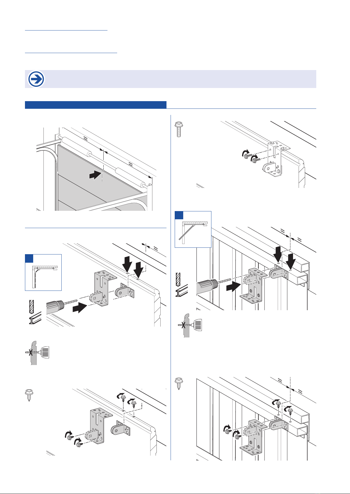
4. Mounting ........................................................................................................................................................ 7
4.1 Installation preparation ............................................................................................................................... 7
4.2 Mounting..................................................................................................................................................... 8
4.3 Control connections.................................................................................................................................. 11
4.3.1 Overview of control connections......................................................................................................... 11
4.3.2 Connection at terminal strip K............................................................................................................. 12
4.3.3 Connection of the receiver (preinstalled) ............................................................................................ 12
4.4 Mounting completion ................................................................................................................................ 12
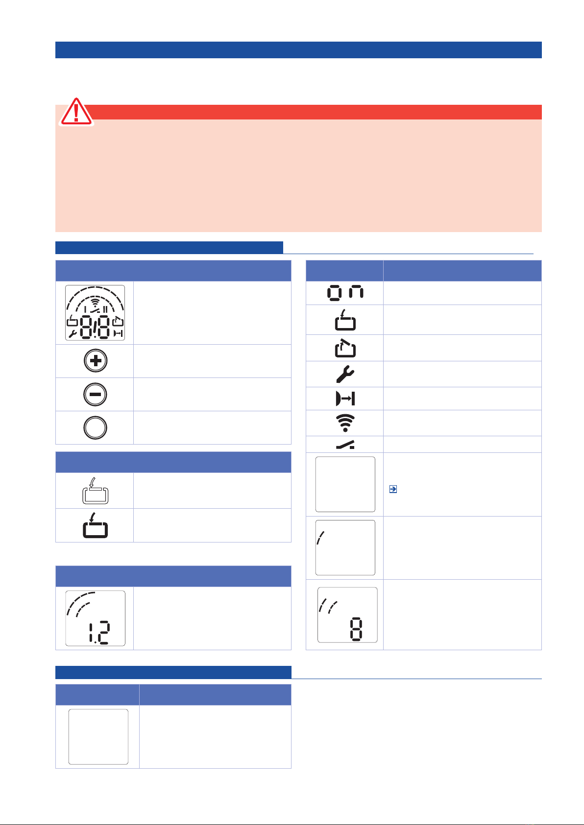
5. Putting into operation.................................................................................................................................. 13
5.1 Overview central unit................................................................................................................................ 13
5.2 Status display ........................................................................................................................................... 13
5.3 Quick programming .................................................................................................................................. 14
5.4 Factory settings ........................................................................................................................................ 15
5.5 Function test............................................................................................................................................. 15
5.5.1 Learning cycle..................................................................................................................................... 15
5.5.2 Automaticswitch-ocontrol................................................................................................................ 15
5.5.3 Photocell test ...................................................................................................................................... 15
Special points regarding the door-frame photocell ............................................................................. 15
5.6 Special programming................................................................................................................................ 16
5.6.1 Programming the special functions..................................................................................................... 16
5.6.2 Overview on Special functions............................................................................................................ 17
5.6.3 Content of special functions................................................................................................................ 17
6. Operation ...................................................................................................................................................... 23
6.1 Transmitter ............................................................................................................................................... 23
6.2 Release .................................................................................................................................................... 24
7. Maintenance, care and cleaning ................................................................................................................. 25
8. Disassembly ................................................................................................................................................. 25
9. Disposal ...................................................................................................................................................... 25
10. Troubleshooting ........................................................................................................................................... 26
Faults with no fault messages .................................................................................................................. 26
Faults with fault messages ....................................................................................................................... 27
11. RADIO programming.................................................................................................................................... 28
Saving and deleting transmitters ............................................................................................................. 28
11.1 Saving a new transmitter.......................................................................................................................... 29
11.2 Deleting transmitters................................................................................................................................. 30
11.3 Troubleshooting and technical data radio RS 868................................................................................... 30
12. Photocell LS 55/3 (optional) ........................................................................................................................ 32
13. Flashlight module (optional) ....................................................................................................................... 34
14. Safety edge module (optional).................................................................................................................... 36
15. Dimensional drawing ................................................................................................................................... 38
Installation declaration ................................................................................................................................ 39

tousek / EN_GTZ-Digital_07 / 10. 10. 2019 - 3 -
About this document
• Original instruction manual
• Is part of the product
• Please read this manual and keep it accessible all the time
• Protected by copyright.
• The reproduction of this instruction manual, in whole or in part, is allowed only with our permission
• Subject to technical modifications and improvements in the interest of technological progress
• All dimensions in millimeters
• The illustrations are not in scale
Explanation of symbols
Danger!
This safety instruction points out a danger, that will imme-
diately result in death or serious injury.
Indication
This safety instruction points out a danger, that can lead
to damage or destruction of the product.
Warning !
This safety instruction points out a danger, that will result
in death or serious injury.
Inspection
Indication for a needed inspecion.
Attention!
This safety instruction points out a danger, that can result
in minor or moderate injury.
Indication
Other important information for installation and operation.
Reference
Factory setting
DANGER!
IMPORTANT SAFETY INSTRUCTIONS:
ATTENTION - FOR PERSONAL SAFETY, IT IS VITAL TO FOLLOW ALL INSTRUCTIONS.
PLEASE KEEP THIS MANUAL READILY ACCESSIBLE.
IMPORTANT INSTRUCTIONS FOR A SAFE INSTALLATION:
ATTENTION - IMPROPER INSTALLATION CAN RESULT IN SERIOUS INJURY.
PLEASE FOLLOW ALL MOUNTING INSTRUCTIONS.

- 4 - tousek / EN_GTZ-Digital_07 / 10. 10. 2019
General safety information
Danger !
Risk of death by non-compliance with the documentation!
Observe all safety instructions in this document.
1.1 intended use
• The drive system is intended solely for the opening and opening of garage doors.
• Persons or objects should never be moved by means of the garage door.
for the product 55 Digital GTZ, GTZ 110 Digital applies:
• Operation is only permitted in dry rooms.
• Following details must be taken into account:
- maximum pull force
- maximum compression force
- maximum door size
- maximum door weight
„Technical data“, page 5
• The product is intended for private use
• The product is suitable only for counterbalanced sectional doors and overhead doors with appropriate fall protection.
1.2 Target group
• Installation, connection and commissioning: qualified, trained personnel.
• Operation, inspection and maintenance: owner/operator of the door system.
Requirements for qualied and technical sta:
• Knowledge of the general and specific safety and accident-prevention regulations.
• Knowledge of the relevant electrical regulations.
• Training in use and maintenance of adequate safety equipment.
• Adequate training and supervision by qualified electricians.
• Ability to identify hazards that may be caused by electricity.
Knowledge of the following standards
- EN 12635 („gates - Installation and use“),
- EN 12453 („gates - Safe use of power-operated doors – requirements“),
- EN 12445 („gates- Safe use of power-operated doors – test procedure“).
Requirements for the owner of the door system:
• Knowledge and Storage of operating instructions.
• Knowledge of general safety and accident prevention regulations.
1.3 Warranty
The product is manufactured in accordance with the directives and standards mentioned in the manufacturer declaration and
declaration of conformity.
The product has left the factory in a safe and secure technical condition.
In the following cases, the manufacturer assumes no liability for damages. The warranty on product and components expires
in case of:
• Non-observance of these operating instructions.
• Improper use and handling.
• Use of non-qualified personnel.
• Modifications and changes of the product.
• Use of replacement parts, that were not produced or approved by the manufacturer.
• Excluded from the warranty are batteries, fuses and bulbs.
Additional safety information available in the relevant sections of the document.
„4. Installation“
„5. Commissioning“
„6. Operation“
„7. Maintenance“
„8. Dismantling“

tousek / EN_GTZ-Digital_07 / 10. 10. 2019 - 5 -
General GTZ 55, 110 Digital
Features
• Operator for spring balanced garage doors, regardless whether overhead swing-up, swing-out or sectional doors
• GTZ 55: with 550N traction and shear force (up to 3 parking places)
GTZ 110: mit 1100N traction and shear force (up to 10 parking places)
• Integrated LED lamp
• For low lintel heights (35mm)
• Soft start
• Soft stop (2-steps at closing)
• Automatic reversal (= impact detection)
• Automatic mode
• Self-adjusting end positions
• Self-adjusting force (force curve) for max. safety
• Easy programming through
3 buttons and LC-Display
• with belt
• Incl. self-adjusting radio receiver and
4-channell transmitter RS 868
• Incl. rail and mounting equipment
•
Technical Details
Garage door opener GTZ- 55 Digital 110 Digital 55 Digital 110 Digital
Nominalvoltage,country-specic
deviations possible 230 / 260V, 50 / 60Hz max. thrust and
compressing force 550N 1100N
Current consumption 1,1A Max. running speed 160mm/s
Power consumption
(no accessories
connected)
In opera-
tion 0,25kW Opening speed, depending
on the door ca. 14s
Stand by ca. 4W Total weight 6,4kg 6,6kg
Duty cycle KB 2min. Sound pressure level <70 dB(A)
Control voltage 24V d.c. Working temperature -20°C to +60°C
Protection class motor unit IP 20
Rail
(moving stroke)
Typ 1 2,47m
Protection class II Typ 2 2,72m
Max. cycles / day 20 50 Typ 3 3,48m
Kit-components
1 operator• 1 rail incl. mounting material (split or unsplit)
with
belt
•
1 radio receiver RS 868, 1-channel
• 1 transmitter RS 868, 4-channels
Optional components
Additional locking (spring latch kit) • Emergency release from the outside • bowden cable for GTZ (3m
cable length) • photocells LS 55/3 • safety edge module • flashlight module • LED extension
ATTENTION: This operatorcan be installed indoors only!
Under no circumstances it should be exposed to rain or moisture, like in an open carports!
Application
Garage door opener GTZ- 55 Digital 110 Digital
Type of door max. door width max. door weight max. door width max. door weight
Overhead doors 3.500mm
90kg 6.000mm 200kgSingle-walled sectional doors 5.000mm
Double-walled sectional doors
3.000mm
327
188
120

- 6 - tousek / EN_GTZ-Digital_07 / 10. 10. 2019
2. Scope of delivery GTZ 55, 110 Digital
The product is supplied in different versions.Use the chart and the scope of delivery to check which version you have.
Country-specific variations are possible.
Pos. Motor A
11x
21x
31x
42x
Pos. Fittings A
52x
61x
72x
81x
92x
10 1x
11 1x
Pos. Connecting elements- 01 A
13 4x
14 2x
15 1x
16 1x
17 1x
18 1x
19 2x
20 1x
21 1x
22 1x
Pos. Connecting elements - 02 A
24 6x
25 6x
26 6x
Pos. Warning labels A
27 1x
28 1x

tousek / EN_GTZ-Digital_07 / 10. 10. 2019 - 7 -
3. Door system GTZ 55, 110 Digital
The door system is just an example and may vary depending
on the type of door and the associated equipment.
The door system here illustrated consists of following com-
ponents:
(1) photocell
(2) key lock
(3) stand (for code pad, Transponder, ...)
(4) signal lamp
• On the manufacturer´s homepage you´ll find
further information about the accessories.
• For installing and cabling the gate sensors,
impulse emitters and safety devices carefully
note the corresponding manuals.
4. Mounting GTZ 55, 110 Digital
Danger !
Before commencing cabling works please disconnect the operator system from the power supply
• Make sure that the power supply remains disconnected during cabling works
• Observe the local safety regulations.
• Important: lay power and control cables separately. The control voltage is 24 V D.C.
Material damage due to improper installation of the motor!
To avoid installation errors and damage to the door and to the operator system, please follow the assembly
instructions.
• Make sure that the door is in a good mechanical condition:
- The door comes to rest in anyposition.
- The door can be moved more easily.
- The door opens and closes properly.
• Install all impulse and control devices (eg. radio code keypad ) within sight of the gate and at a safe distance from the
moving parts of the door. A minimum mounting height of 1.5 m must be observed.
• Use only fastening material suitable for the particular construction site.
4.1 Installation preparation u Mounting
Before beginning installation the following works have to be necessarily carried out:
Delivery scope
• Check which version you have and whether the delivery is complete.
• Make sure that a you have a suitable operator rail.
• Check if you have all the accessories required.
Garage
• Check if your garage has a suitable mains connection and a main switch.
Door system
• Remove any locking devices, that are not required (eg emergency release cord).
• Put all those devices, which are not required after installing the garage door opener, out of operation..
For garages without a second entrance:
• Equip the garage door with an emergency release, in order to beeing able to enter the garage also in case of a malfunction.
3
1
12
4

- 8 - tousek / EN_GTZ-Digital_07 / 10. 10. 2019
If you are using a releasing kit:
• Check the correct function of the locking devices. These may be put out of order by no means.
If you are not using a releasing kit:
• Remove the locking mechanisms or put them out of operation.
When using and installing accessories, please observe the relevant documentation.
4.2 Mounting Mounting
=
=
A
B
Ø 5–5,5
4x
2x
4x
Ø 5–5,5

tousek / EN_GTZ-Digital_07 / 10. 10. 2019 - 9 -
Important
Possible damage to the motor unit!
• Do not use force, since otherwise the gear can be
damaged!
• Mount the drive rails carefully onto the motor unit.
Warning !
Severe injuries due to falling objects!
• Prevent the drive system from falling by fixing it well .
A
B
1x
4x
1x
4x
1x
10–50
Ø 10
2x
2x
2x
Important
Possible damages of the door leaf!
• The door leaf top edge must be at the highest point
of the opening path 10 - 50 mm below the horizontal
bottom edge of the drive rail.
• Mount the lintel joining plate for the operator track
centered over the door leaf.

- 10 - tousek / EN_GTZ-Digital_07 / 10. 10. 2019
5–10
a
b
1.
2.
3.
1.
2.
1.
2.
1x
1x
1x
2x
1x
1x
a = 90°
b = 9Nm
limit stop for OPEN position
Install the limit stop for the OPEN position
as shown above!
• The position of the limit stop on the rail defines how far
the gate opens.

tousek / EN_GTZ-Digital_07 / 10. 10. 2019 - 11 -
4.3 Control connections u Monting
Risk of death through electric shock hazard!
• Before commencing cabling works please disconnect the operator system from the power supply
• Make sure that the power supply remains disconnected during cabling works.
Material damage due to improper installation of the actuator!
An external voltage at the terminal K results in the destruction of whole electronics.
• Connect to the terminals 1, 2 and 4 (K) only potential free contacts.
4.3.1 Overview of control connections
Connection
K
– External control elements
– Photocell, stop switch, accessories
„Level 5, Menu 1 - Programmable impulse input
(clamp 1/2)“
„4.3.2 Connection on terminal K“
E
Connection MS-BUS for extension modules:
- safety edges module (optional)
„Level 8, Menu 2 - safety sensing edge
FE Connection radio receiver RS 868-GTZ
„4.3.3 connection receiver“
1.
2.
3.
Ø 10
2x
2x
2x
2/3
1/3
K E
FE
preinstalled

- 12 - tousek / EN_GTZ-Digital_07 / 10. 10. 2019
K
F
S
F
A
FE
S
1common
2impulse switch
324Vd.c. +/max. 50mA
4stop switch (normally closed contact), active after reset
70 common LS 55/3 cable 1: black/white marked
71 photocell LS 55/3 cable 2: no mark
4.3.2 Connection terminal strip K
4.3.3 Connection of the receiver (preinstalled)
• The RS868-GTZ radio receiver (F) is preinstalled and located
under the cover (A), which can be pulled out in upwards
direction.
• Connect the radio receiver plug (S) to the operators con-
nection slot (FE).
4.4
Mounting completion
u Mounting
• Attach the warning signs against permanently at a position
where they are clearly visible.
• Make sure that after the installation no door parts are spread
onto public footpaths or roads.
• Stop button and 2-wire photocell will be
recognized and activated automatically after
switching on the power.
• There is no need to set jumpers, if these devices
are not connected.
• However, once detected the devices must remain
connected.
• Only by carrying out a RESET you can reset
the functions.
Note the
cable marking!
7170
TX RX
123 4
1 2
terminal strip K
photocell LS 55/3
„12. photocell LS 55/3“
transmitter receiver
3 1 2 4 70 71
impulse button
stop button
24V 0V
1 2 1 2

tousek / EN_GTZ-Digital_07 / 10. 10. 2019 - 13 -
5. Putting into operation GTZ 55, 110 Digital
Power-operated windows, doors and gates must be checked by a specialist ( with written evidence) before first com-
missioning at least once a year or any time it is necessary. After installation and commissioning the owners of the
door system or his representative must be instructed on its functions and proper operation.
Warning !
Risk of injury due to uncontrolled door movement!
Make sure that children cannot play with the central unit or with the remote controls of your opener.
• Before operating the garage door, make sure that no persons /objects are within its range of movement.
• Prior to passing the door make sure that the door is in the OPEN position.
• Test all existing emergency stop devices.
• Pay attention to any parts of the door system that could cause crushing or shearing damage or accidents.
• Never touch or reach into the moving door, guide rail or moving parts.
• The regulations of the standards EN 13241-1 („ Industrial, commercial and garage doors and gates - Product
standard“) must be observed.
Operating elements
1
2
3
4
5
6
7
8
9
0
LC-Display
Move the garage door in direction „OPEN“,
increment parameters
Move the garage door in direction „CLO-
SE“, reduce parameters
Pstartprogramming,conrmandsave
parameters
Legend
Display blinks
Display lights up
Display Function / Element
Operational
Door position CLOSED
Door position OPEN
Error message / Maintenance indicator in
CLOSED position
Photocell or closing edge protection
Radio control
External switch
4
Status display
„5.2 Status display“
1
2
3
4
5
6
7
8
9
0
Display of the levels (Example: level 2)
1
2
3
4
5
6
7
8
9
0
Display of the menus and parameters
(Example: Menu 3, Parameter 8)
Minute display
1
2
3
4
5
6
7
8
9
0
Time periods over one minute are shown
in minutes and seconds.Example: 1.2 = 1
minute + 20 seconds =
80 secunds
5.1 Overview central unit u Commissioning
5.2 Status display u Putting into operation
Status display Function / element
4
Indicator for warning time (only by pro-
grammed automatic closing)

- 14 - tousek / EN_GTZ-Digital_07 / 10. 10. 2019
5.3 Quick programming u Putting into operation
For a proper start-up of the drive system and after a reset, a quick programming must be carried out.
Requirements:
• The door is in CLOSED position.
• The guide carriage is engaged „6.2 Releasing“
When in programming mode, if within 120 seconds no buttons are pressed, the control reverts to operating mode. You will see
a corresponding error number. „10. Troubleshooting“
• carry the quick programming out.
• After the quick programming a functional test must be carried out. „5.5 Functional test“
Quick programming
1. Programming of the door position OPEN 2. Programming of the door position CLOSED
Control unit is in opera-
ting mode
Bring the door to the
CLOSED position
PP > 3 Sec. < 10 Sec.:
Begining of the quick
programming PSave the door
position CLOSED
Bring the door to the
OPEN position
Control unit is in
operating mode
PSave the door position
OPEN
3. Radio-programming (memorizing the 1st transmitter)
• Press the memory button P1 of the receiver board and
keep it pressed. After about 0.8 sec., the buzzer emits
a continuous tone.
• While holding P1 pressed, press the transmitter channel
button, you want to store.
• If the memory process is completed, the buzzer of the
receiver emits successive tones. The remote control code
is therefore stored.
If additional transmitter have to be stored, so the whole
process must be repeated. z.B.
P1
P1
Full description of of the radio „11. Radio- programming“ .

tousek / EN_GTZ-Digital_07 / 10. 10. 2019 - 15 -
5.4 Factory settings stellu Putting into operation
A reset can bring the drive back to the factory settings.. „Level 1, menu 8 - RESET“
5.5 Function test stellu Putting into operation
5.5.1 Learning cycle
Move drive system (with engaged door) without interruption even from the CLOSED position to the OPEN position and back.
• The drive system learns the maximum required driving power during the first two cycles and after setting the door positions.
• Check the driving force.
Checking the driving force
1. Control unit is in operating
mode 4. The operator must OPEN or
CLOSE the gate.
2.
The door has to open and
move towards the memorized
door psition OPEN
5. The operator must stop.
3.
The door has to close and
move towards the memorized
door psition CLOSED
6. The operator moves into the
opposite direction.
5.5.2 Automatic switch-o control
Warning !
Risk of injury due to incorrect adjusted gate force! Check the automatic switch-off OPEN and CLOSE.
Automatic switch-o OPEN
Check only when the gate has holes (diameter of the hole > 50 mm):
• During the travel, apply a load of 20kg to the gate at the mid point of the bottom edge of the gate: The gate must immediately stop.
Automatic switch-o CLOSE
Check for all gate types.
• Place a 50mm high object on the floor.
• Drive the gate toward the obstacle: the operator system should stop and reverse when it touches the obstacle.
The driving force settings for OPEN and CLOSE remain saved even if the main power supply is interrupted.
The settings will only be resetted after factroy reset. „Level 1, menu 8 - RESET“
5.5.3 Photocell test
Photocell
• Check all the photocells individually by triggering them..
• Please check all the connected photocells short before reaching the CLOSED position.
Special points regarding door-frame photocells
• The door-frame photocell must work above the installed position. Under the installation point is the function suppressed by the
control unit.
• If several photocells are connected, all the photocells work in the same way as the door-frame photocell.

- 16 - tousek / EN_GTZ-Digital_07 / 10. 10. 2019
5.6 special programming stellu Putting into operation
Warning !
Risk of injury due to incorrect adjusted gate force!
Important factory settings can be adjusted under the special programming point.
• Check the programmed parameters.
• Check the adjusted gate force after changing the automatic switch-off parameters. „5.5.2 testing the automatic switch-off“
• Have the automatic switch-off tested by qualified and trained professionals with a force tester designed for this purpsose.
Material damage resulting from incorrect programming of the gate operator!
After a reset, all the adjusted parameters will be factory-resetted.
Connected and functioning safety devices will be recognised again after a factory-reset.
To ensure that the control unit works properly:
• reprogram all the required functions.
• have the operator drive the gate once into OPEN and once into CLOSED position.
If a photocell is connected, it will be automatically detected by the control unit as soon as the power supply is connected. The
photocell can be reprogrammed later.Photocells that are not required must be disconnected before the power supply is con-
nected; otherwise they will be recognised by the control unit. „4.3.3 terminal strip K“.
• A function test must be carried out after changes have been made in programming mode.
„5.5 Function test“
programming the special functions
1. The control unit is in opera-
ting mode.
2. PP > 10 sec.: Start program-
ming the extended operator
functions. Display the levels.
1
2
3
4
5
6
7
8
9
0
3. Select the required level
(e.g. level 2).
1
2
3
4
5
6
7
8
9
0
4. PConrmthelevelrequired.
Displaytherstmenuandthe
programmed parameter.
1
2
3
4
5
6
7
8
9
0
5. Select the required menu
(e.g. menu 3).
1
2
3
4
5
6
7
8
9
0
5.6.1 programming the special functions
6. PConrmtherequiredmenu.
Display the programmed
parameter value.
1
2
3
4
5
6
7
8
9
0
7. Change the parameter value.
1
2
3
4
5
6
7
8
9
0
8. PSave the parameter value.
The control unit switches to
display levels.
1
2
3
4
5
6
7
8
9
0
9.
Select the next required level.
Continue programming.
1
2
3
4
5
6
7
8
9
0
or
PP > 5 sec.:Finish program-
ming. All the adjusted para-
meters are saved.
The control unit is in
operating mode.

tousek / EN_GTZ-Digital_07 / 10. 10. 2019 - 17 -
Level 1 Menu 8 RESET
The operator system can be reset to the factory settings..
1No reset 5Reset only extenden functions
(except door position OPEN/CLOSED)
2 Reset central unit 6 Reset safety devices (photocells / hold circuit)
3 No Function
7Reset Bus Module
(connected bus modules will be deleted)
4Reset extension automatic mode
„level 3, - automatic mode“
5.6.2 Overview on special functions
5.6.3 Content of special functions
Level 1 basic functions
Level 1 Menu 7 relay-output
(programmable only with the optional signal lamp relay)
1Signal lamps (present / not present)
„level 3, menu 7 - Signal lamps“ 8Lighting time „level 5, menu 4 - Lighting time“
2 Door position OPEN 9 locking mechanism release (operator system running)
3 door posiition CLOSED 10 locking mechanism release (operator system stopped)
4 No function 11 release lock (operator system starts / wiping impulse, 3
seconds)
5 No function 12 anti-opening security device
6 Motor system starts (wipe puls 1 second) 13 No function
7 Interference 14 test impulse for the safety sensing edge (relay transmits a
test impulse and is activated for 300 ms)
Ebene Menu
6. variable speed
1 speed OPEN
2 soft run speed OPEN
3 soft run position OPEN
4 speed CLOSE
5 smart run speed CLOSE
6 soft run speed CLOSE
7 smart run position CLOSE
8 soft run position CLOSE
9 soft start time OPEN
10 soft start time CLOSE
7. maintenance and
service
1 gate cycle counter
2 maintenance counter
3 maintenance intervall
8 reset maintenance and service
9 fault display
8. system settings
1 photocell
2safety sensing edge (optional
with additional module)
3automaticswitch-ofunction
4 operating modes
5function of the direction com-
mand transmitters
6 function of the impulse emitters
7stress relief in the CLOSED gate
position (back jump)
8 rotation direction
0special functions
door-frame photocell
Ebene Menu
1. Basic functions
7 relay-output
8 RESET
2. Motor settings
1 driving force required to OPEN
2 driving force required to CLOSE
3automaticswitch-oOPEN
4automaticswitch-oCLOSE
3. Automatic mode
1 automatic closing time
3 gate open duration (pause time)
4 pre-warning time
5 start warning
7 signal lamp
4. Without function
5. Special functions
1
programmable impulse input
4 lighting time
5 optional function
7 optional function

- 18 - tousek / EN_GTZ-Digital_07 / 10. 10. 2019
Level 2 Motor settings
Level 2 Menu 1 Required driving force OPEN = 8
Sensitivity in steps from 1 - 16 (the higher the level, the higher the required driving force).
Level 2 Menu 2 Required driving force CLOSE = 8
Sensitivity in steps from 1 - 16 (the higher the level, the higher the required driving force).
Level 2 Menu 3 Automatic switcho OPEN = 12
Sensitivity in steps from 1 (OFF) - 16 (the lower the level, the more sensitive the automatic switchoff).
Level 2 Menu 4 Automatic switcho CLOSE = 8
Sensitivity in steps from 1 (OFF) - 16 (the lower the level, the more sensitive the automatic switchoff).
Level 3 automatic closing timer
Level 3 Menu 1 Automatic closure
Note: the automatic closure works only when the photocells are connected.
If the automatic closing function is activated, the relay output (Level 1 / menu 7) can be reprogrammed if required..
1Deactivated 5 pause time 5 /warn.time 5
The door open duration ends
after the photocell has been
triggered.
2 pause time15 / warning time 5
The open duration
can only be increased
via an impulse signal
(button, switch or
transmitter).
6 pause time 30 /warn.time 5
3 pause time 30 / warning time 5 7 pause time 60 /warn.time 8
4 pause time 60 / warning time 8 8 innitepausetime/
warning time 3
Door closes after the pho-
tocell has been triggered /
Closing prevention.
Level 3 Menu 3 Pause time Depending on level 3, menu 1
2 – 250 seconds.
Level 3 Menu 4 Warning time Depending on level 3, menu 1
1 – 70 seconds.
Level 3 Menu 5 Start warning, when opening = 0
0 – 7 seconds.
Level 3 Menu 7 Signal light
1Doormovement/warning:ashing
Door stationary: OFF (energy saving) 4Door movement / warning: lighting
Door stationary: lighting
2Door movement / warning: lighting
Door stationary: OFF (energy saving) 5Doormovement/warning:ashing
Door stationary: lighting
3Doormovement/warning:ashing
Door stationary: blinking 6Door movement / warning: lighting
Doorstationary:ashing
Level 4 no function

tousek / EN_GTZ-Digital_07 / 10. 10. 2019 - 19 -
Level 5 Special functions
Level 5 Menu 1 programmable impulse input (terminal 1/2)
1
Impulse (normally open contact)
in automatic mode only opening command,
When opening: No function
During the pause time: Restart the pause time
When closing : Reversing till door is open
5
OPEN impulse (normally open contact)
during the movement: no function
if automatic closing is activated: pause time extension and
reverse when closing
2 closing prevention (normally open contact) 6 earlier closing possible by pressing the impulse button or
transmitter > 2 seconds
3Stops and reverses (only direction door CLOSED -
normally close contact)
7impulse (normally open contact only) with permanent
24V DC / max. 50mA power supply
4Stops and reverses (only direction door CLOSED -
normally open contact)
Level 5 Menu 4 lighting duration = 3.0 (180 seconds)
2 – 250 seconds.
Level 5 Menu 5 Optional function = 1 (do not change)
Factory settings = 1 - do not change!
Level 5 Menu 7 Optional function = 1 (do not change)
Factory settings = 1 - do not change!

- 20 - tousek / EN_GTZ-Digital_07 / 10. 10. 2019
Level 6 variable speed
Level 6 Menu 1 Speed OPEN = 16
Steps from 5 - 16.
Level 6 Menu 2 Soft speed OPEN = 8
Steps from 1 - 16.
Level 6 Menu 3 Soft run position OPEN
Adjustment with button + (OPEN) and – (CLOSE).
Level 6 Menu 4 Speed CLOSE = 16
Steps from 5 - 16.
Level 6 Menu 5 Speed smart run CLOSE = 8
Steps from 5 - 16.
Level 6 Menu 6 Speed soft run CLOSE = 8
Steps from 1 - 16.
Level 6 Menu 7 Smart run position CLOSE
Adjustment with button + (OPEN) and – (CLOSE).
Level 6 Menu 8 Soft run position CLOSE
Adjustment with button + (OPEN) and – (CLOSE).
Level 6 Menu 9 Soft start time OPEN
1Soft start time 1 seconds 3 Soft start time 3 seconds
2 Soft start time 2 seconds 4 Soft start time 6 seconds
Level 6 Menu 10 Soft start time CLOSE
1Soft start time 1 second 3 Soft start time 3 seconds
2 Soft start time 2 seconds 4 Soft start time 6 seconds
This manual suits for next models
2
Table of contents
Other tousek Garage Door Opener manuals