tousek BT 40 Series User manual

Connection and installation manual
Self-learning radio system BT 40
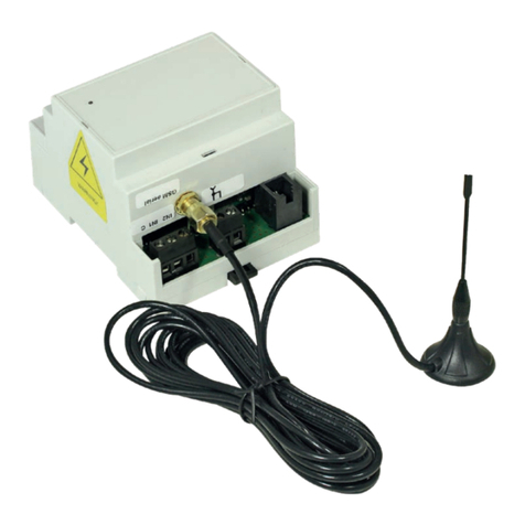
1-channel receiver board BT40-ST, BT40-TT6
1-channel receiver BT40-cable (with connection cable), BT40-SO (with connection socket)

- 2 - tousek / E_BT40_80301105 / 30. 07. 2019
This manual is the sole property of the TOUSEK Ges.m.b.H. and may not be made available to competitors. All rights reserved. No part of it may be reproduced without our prior
written permission. We will not accept liability for any claims resulting from misprints or errors. This edition of the manual replaces all earlier publications of the same.
General warning and safety notes
• Installation, adjustment and maintenance may only be carried out by trained personnel!
• Carrying out works at the receiver is only admissible after the power supply has been turned off!
• Only turn on the power supply again after another check!
• Never feed 230V power supply to low voltage input - This will destroy your unit, no guarantee.
• Please consider polarity for DC use !
• A proper operation is only given, when these installation instructions are strictly followed.
• Protect the transmitters against heat and wetness and don’t expose them to direct solar radiation for a longer period of time.
Used batteries may not be disposed of in the usual household waste, but have to be brought to a collecting point..
Safety
• Store transmitters and batteries out of children’s reach (risk of suffocation through small parts, risk of injury through
unintended operation of the gate facility).
• If the battery is swallowed by a child, please call a doctor immediately.
• Don’t use the transmitter in explosion hazardous areas and also in areas, where the usage of radio systems (e.g.
mobile phones,…) is forbidden.
• The Tousek transmitters may only be used for devices and facilities, where no danger for persons or things arises
from a malfunction of transmitter or receiver, or where this risk is covered by other safety devices.
• The remote controlling of devices and plants with an increased accident risk (e.g. crane facilities) is forbidden!
• For safe operation the local valid safety regulations for the plant have to be kept!
• The owner/user has to be informed that facilities with an increased accident risk may only be operated at direct
intervisibility.
Mounting
Pluggable receiver boards (BT40-TT6, BT40-ST):
• Installation in dry rooms only!
• For a differing installation, an according protective housing (e.g. IP65) has to be foreseen.
Receiver in housing (BT40-SO24V, BT40-SO230V and BT40-cable):
• When using the radio receiver in extreme weather conditions, we recommend using a protective enclosure IP65.
1. General Self-learning radio system BT 40
General features
• The radio receiver of the series BT are performed in self-learning technology, i.e. the coding of the hand transmitter is taught
into the receiver. For the use of transmitters BT40-xB or of Mini-transmitter MT40-A1 the jumper J1 for 2-stage operation
code switch on the receiver must be set !
• Up to 64 dierent codes of the transmitter BT 40-xB can be taught in. Furthermore there is the possibility to erase taught
encodings or the complete memory.
• In combination with antenna FK 4/2 the range can be increased to approx. 100m
• Enclosed antenna (1,8m length)
•
Technical data Receiver
Receiver frequency : 40,685 MHz
Internal oscillator frequency: 40,230 MHz
Sensitivity: 1 µV
Intermediate frequency: 455 kHz
Impedance antenna input: 50 W
Operating temperature: -20 up to +55°C
Delay 2-stage system: 300 ms
Delay 3-stage system: 80 ms
Switch-o 2-stage system 600 ms
Switch-o 3-stage system: 300 ms
Technical data transmitter
Frequency: 40,685 MHz
Tolerance range: 30 ppm of -10°C bis +55°C
Radiated power: 200 µW
Modulation: AM/ASK
Average Power Consumption: 40 mA
Operating temperature: -10°C up to +55°C
Number of combinations (2-stage): 1024
Available channels: 1, 2 or 4
Technical data Radio system BT 40

tousek / E_BT40_80301105 / 30. 07. 2019 - 3 -
75
75
38
75
75
38
43
31
55
62
A
P2
P1
J1
L1
2. Receiver Self-learning radio system BT 40
1-channel Receiver in housing Receiver BT 40
1-channel receiver with 11-pole plug socket
BT40-SO24V 24V a.c./d.c. Art.No. 13260020
BT40-SO230V 230V a.c. Art.No. 13260010
1-channel receiver with 4-pole connection cable
BT40-cable 24V a.c./d.c. Art.No. 13260080
1 2
1-channel receiver boards Receiver BT 40
1-channel receiver board with connector strip
pluggable into garage door operator TT60/120 K3
BT40-TT6 Art.No. 13260040
31-channel receiver board with connector strip
pluggable into control boards ST3 and PULL X/1
BT40-ST Art.No. 13260030
4
Antenna looped onto board
3. Transmitter models BT 40 Self-learning radio system BT 40
for more detailed information see the corresponding manual
• Transmitter BT40
12V, 40MHz, grey keypad, compatible with previous wireless system HS40)
BT40-1B 1-channel Art.No. 13150010
BT40-2B 2-channels Art.No. 13150020
BT40-4B 4-channels Art.No. 13150030
P2 P1
P2 P1
A*
A*
L1
L1
L1 LED
P1 save
P2 delete
A Antenna connection
J1 place Jumper onto
2- stage
code switch
(„BIN.”)!
J1
55
60
A
P2
P1
L1
* plug-in terminals for antenna connection

- 4 - tousek / E_BT40_80301105 / 30. 07. 2019
4. Connection of receivers Self-learning radio system BT 40
Antenna connection
For optimum function an antenna necessarily needs
to be connected.
Normally the enclosed wire antenna is sucient (wire
from 1.8 m length), this one must be cross-clamped
in full-length and connected onto the receiver antenna
input. Longest range results in a installation away by a
large distance to metal parts (heating pipes, concrete
ceilings, cables, etc.). The ideal location has to be
determined by doing tests.
Under certain circumstances, and to increase the range
and a coordinated rod antenna can be used (model
FK 4/2). It is important that the shield is connected
as indicated.
1
2
3Connection examples receiver boards
(pluggable) Antenna
Antenna connection optionally also pos-
sible onto board (eg PULL X) .
Receiver with plug socket (11 poles)
Receiver with cable connection
Connection example BT40-cable
terminal block
PULL T5, -8, -10
BT40-SO230V BT40-SO24V
230V a.c. 24V a.c./d.c.
relay output relay output
-
+
shield
antenna cable
e.g.
BT40-TT6
4
When using the radio receiver in extreme
weather conditions, we recommend using a
protective enclosure IP65.
e.g. control board ST3
BT40-ST
brown
blue
black
black
power supply
24V AC/DC
relay output
Legend:
+/~
-/~
Antenna FK 4/2
BT40-TT6
e.g. control board TT60 K3
Antenna
shield
shield
J1
Important
• Place J1 Jumper
onto 2- stage
code switch
(„BIN.”)!
J1
black
black
blue
brown
Antenna
shield
BT40-cable
40
41
43
45
46
31
37
32
30
33

tousek / E_BT40_80301105 / 30. 07. 2019 - 5 -
The transmitters BT40-1B, BT40-2B and BT40-4B (with gray
keypad) feature a 2-step code switch for for assigning the code
or the channel (ie each switch can be either “ON” or “OFF”).
For settings on the code switch you need to open the trans-
mitter (remote control).
To do this, place the cover between thumb and forenger and
push the lid of the remote control rmly together and upwards.
• 1- and 2-channel transmitters
have a 12 digit code switch:
Switch 1–10: code adjustment
Switch 11–12: channel assignment (K1–K4):
With 1-channel transmitters the transmitter button 1 can
be assigned to any of the channels (K1–K4).
With 2-channel transmitters the transmitter key 1has a
xed assignment to K1. The button 2can be assigned via
DIP 11 and 12 to one of the channels K2–K4.
• 4-channel transmitters
have a 10 digit code switch:
Switch 1–10: code adjustment
• Coding of mini-transmitter MT40-A1
see corresponding additional user manual
xed channel assign-
ment:
1 > K1
2 > K2
3 > K3
4 > K4
4. Coding and key assignment of transmitter BT 40 Radio system BT 40
Important
• For the use of the transmitters BT40-xB or Mini-
transmitter MT40-A1 the Jumper J1 for 2-stage code
operation has to be set on the receiver !
• The position of all DIP switches to „OFF“ or „ON“
switch to the code of the transmitter is not permitted!
1
24
3
xed: K1
12
1
ON
1 2 3 4 5 6 7 8 9 10
+
ON ON ON OFF OFF ON OFF OFF
K1 K2 K3 K4
ON
1 2 3 4 5 6 7 8 9 10 11 12
+
11 1211 12 11 1211 12

- 6 - tousek / E_BT40_80301105 / 30. 07. 2019
5. Delete / Saving of transmitters Radio system BT 40
P1 P2
+
P2 ON
1234567891011 12
+
+
Programming new transmitters
In the memory of the receiver up to 64 dierent codes can
be taught in. It is therefore possible to open a certain door/
gate with transmitters in dierent encodings. Before starting
the learning process, set a personal code in the transmitter.
Attention: The switch positions “all ON” or
“all OFF” are not permitted.
Now press the receiver button P1 and hold it. After about 0.8
sec. the red LED will glow on.
In addition to P1 Press and release the button on the
transmitter to be learned. The red LED begins to ash. The
remote control code is therefore stored. If additional transmit-
ters are taught, the complete procedure must be repeated.
Attention
If the code can not be memorised into receiver then
this is due to dierent reasons:
• The code is already in the memory
•
The memory is full (max. 64 dierent codes are possible)
• The DIP Switches in transmitter are all set to ON or
OFF.
• Assignment 2-stage, 3-stage coding not applicable.
Delete a single transmitter code from the memory.
Press the receiver button P2 and keep it pressed. After about
0.8 sec. the red LED on the receiver begins blinking slowly.
Press and release the individual button on the transmitter
to be deleted. Once it is deleted, the LED blinks quickly.
Delete of complete memory
Press the receiver buttons P1 and P2 at the same time
and keep them pressed. The red LED on the receiver starts
blinking. After 8 seconds (approx. 15 blink cycles) the LED
illuminates permanently. Now the memory content is deleted
and you can release the buttons.
Legend:
Meaning of drawings for programming/deleting of transmitters:
= press and hold corresponding button
=
transmitter channel button has been programmed
=
transmitter channel button has not been programmed
=
LED on receiver blinks / blinks fast / illuminates
1) After having performed the connection, turn on the power supply.
2) Before you program the transmitters, delete the entire memory contents of the receiver for safety reasons. (see
delete the complete memory contents)
8 seconds
e.g.
BT40-TT6
P1
ON
1234567891011 12
+
Code
ON
1234567891011 12
+
+
shield
antenna cable
P1 P2 L1
L1 LED
P1 memory button
P2 delete button
A Antenna connector
e.g.
BT40-SO24V or
BT40-SO230V
Antenna connector
pluggable
shield
Antenna
P2 P1
A
L1
A

tousek / E_BT40_80301105 / 30. 07. 2019 - 7 -
6. Error diagnosis Radio system BT 40
Error Possible reason Check
Relay of receiver does not switch duri-
ng transmission signal no power supply
Is the radio receiver supplied by the
correct voltage?
receiver board correctly plugged to
connector strip ?
transmitter not memorized see Delete and programm new trans-
mitters
transmitter defective check battery, resp. let transmitter be
controlled
Transmitters only have a small range
of transmission battery in transmitter empty check batteries
Poor Antenna Relocation.
Antenna not or wrongly
connected
see antenna connection
RADIO RECEIVER
BT 40-ST 12V d.c. IP00 1 - / •13260030
BT 40-TT6 12V d.c. IP00 1 - / •13260040
BT 40-Kabel 24V a.c./d.c. IP20 1 230V/60W / •13260080
BT 40-SO24V 24V a.c./d.c. IP20 1 230V/60W / •13260020
BT 40-SO230V 230V a.c. +6%, -10% IP20 1 230V/60W / •13260010
50 Hz ± 0,5%
TRANSMITTERS channels power supply key colour
transmitter BT 40-1B 1 12V alkaline battery (L1028) gray 13150010
transmitter BT 40-2B 2 12V alkaline battery (L1028) gray 13150020
transmitter BT 40-4B 4 12V alkaline battery (L1028) gray 13150030
Optional equipment:
Battery for transmitter BT 40, 12V alkaline, L1028 13140010
Antenna FK4/2 for 40MHz, with 2m coaxial cable for increased range 13250100
Wall bracket incl. clip, for transmitter BT 40 / RS 433 (black) 13150070
Plastic housing für Funkempfänger, IP 65, HxWxD: 200 x 155 x 80mm 12140190
Power supply
Number of channels
max. contact load
ST3, PULL-X/1
TT60-K3, TT120-K3
with 11-pole connection socket
with 4-pole connection cablel
pluggable into
control board
Protection class
Article-No.
DIP-Switches for adjustments
7. Overview of Radio system BT 40 Radio system BT 40

your service partner:
Tousek Ges.m.b.H. Austria
A-1230 Vienna
Zetschegasse 1
Tel. +43/ 1/ 667 36 01
Fax +43/ 1/ 667 89 23
Tousek GmbH Germany
D-83395 Freilassing
Traunsteiner Straße 12
Tel. +49/ 8654/ 77 66-0
Fax +49/ 8654/ 57 196
Tousek Benelux NV
BE-3930 Hamont - Achel
Buitenheide 2A/ 1
Tel. +32/ 11/ 91 61 60
Fax +32/ 11/ 96 87 05
Tousek Sp. z o.o. Poland
PL 43-190 Mikołów (k/Katowic)
Gliwicka 67
Tel. +48/ 32/ 738 53 65
Fax +48/ 32/ 738 53 66
Tousek s.r.o. Czech Republic
CZ-252 61 Jeneč u Prahy
Průmyslová 499
Tel. +420 / 777 751 730
We reserve the right to change dimensions and/or technical specications with-
out prior notice. Claims resulting from misprints or errors cannot be accepted.
tousek PRODUCTS
• sliding gate operators
• cantilever systems
• swing gate operators
• garage door operators
• folding door operators
• trac barriers
• electronic controls
• radio remote controls
• key operated switches
• access control
• safety devices
• accessories
tousek
E_BT40_80301105
30. 07. 2019
This manual suits for next models
17
Table of contents
Other tousek Receiver manuals
