Maxcom MX4RR-LI User manual

MX4RR-LI
Low Power 4 way Return Path Optical Receiver
I Product Introductions:
· High quality optical receiver device for photoelectric conversion
· High-performance dynamic noise isolation switch (DNIS optional)
· 5~65 MHz RF bandwidth to meet various CATV system requirements
· High quality low power reverse amplifier module, improves reliability
· Modular design, independent four-channel receiver module, adopts all-metal
shielded housing, greatly increasing isolation between ports.
· RFoG or Normal - two operating modes optional
· High quality switching power supply, wide range and high reliability
· Electric circuit safety (over-voltage, lightning protection)
· Simple LCD display control and network management interface
II Performance Introductions:
1、Structure Characteristics
The MX4RR-LI reverse optical receiver is an indoor 1U structure, it has four
independent return path optical receivers, 4 optical inputs. 4 independent RF outputs
using F-type connectors. The output signal level may be adjusted by pressing the front
panel key, the adjustment range is 30dB.

2、Front and rear panel layout:
TR R 7 8 0 0 O P T ICA L R E TU R N R EC EIV E R
L
-20dB OUT
RX4 RX3
RX2 RX1
Network
Management
RFOG
220V~50Hz
NORMAL
OP IN
-20dB OUT -20dB OUT -20dB OUT
Mode
Select
SC/APC Available
FC/APC Available
OP IN OP IN OP IN OP IN
RX1RX2RX3
RX4
NO.
Name
Functions
1
LCD Display
Displays information, parameters and working status:
·RFoG ReturnRX
(MAXCOM) initial state, indicating the RFoG reverse
optical receiver
·MODEL: MX4RR-LI
SN: (xxxxxxxx) indicating the optical receiver
module and cascade
·RX(x) ATT: (x)dB
Power In: (low / x dBm) indicates the attenuation and
receiving optical power
·When display status button has not been pressed for 5
seconds, LCD display back light will dim, unit returns to the
initial state.
2
Display
Status Button
There are three buttons:
“▲”: turns the page in the initial state; increase output power/
decrease the amount of attenuation in the channel status,
1dB step, the minimum amount of attenuation is 0dB.
“▼”: turns the page in the initial state; decrease output
power/ increase the amount of attenuation, 1dB step, the
max amount of attenuation is 30dB.
“
TR R 7 8 0 0 O P TICA L R ETU R N R ECEIV ER
L
”: the enter key, turns the page
3
FC/ APC
Interface
(Optional) Input return optical signal when matching FC/ APC
interface, a total of 4.
4
-20dB
Detection
Port
Indicates the RF signal level of each port, measured values
plus 20dB is the true level
5
RF Signal
Output Port
Outputs each port RF signal respectively
6
SC/ APC
Interface
(Standard) Input return optical signal when matching SC/
APC interface, a total of 4
7
RJ45
Interface
Combined with appropriate hardware and software can be
connected to the local computer as a network management
interface. (Optional)
1
2
3
5
6
7
9
8
10
11
4

8
Check Mark
Indicates the fiber connector type
9
Mode
Selection
Switch
Indicates the operating mode, there are two selections:
·RFoG Low power receive ,ode, receiving optical power is
-20~-5dBm;
·Normal The normal output receive pattern, the receive
optical power is -5~0dBm, with AGC
10
Power Switch
and Socket
Power and display for electric circuit, AC 110V, 60Hz
exchange input plug
11
Ground Pole
Uses to ground the housing
3、Principle of MX4RR –LI low power return path optical receiver
Figure 3
MX4RR –LI low power return optical receiver has is fully functional; it has an
excellent RF signal amplifier and flatness correction circuit. Modulation laser signal
feeds into optical receiver detectors, converts optical signals to RF signals. In order to
avoid excessive or too high RF signal level caused by optical modulation increases,
the attenuator is designed after the amplification stage, CPU controls adjust the RF
signal level. CPU control displays the circuit and is also responsible for the collection
and display of relevant parameters, basis warning, and at the same time, it is also
responsible for the display and the external communications capabilities.

III Specifications
NO.
Items
Unit
Performance
Remark
Optical
1
Wavelength
nm
1260~1590
2
Input Power Range
dBm
-20~0
Recommended range,
receiver will operate to
-27dBm
3
Return Loss
dB
>45.0
4
Power Instruction
Precision
5%
RF
5
RF Passband
MHz
5~65
6
Output Level
dBmV
≥20
Input optical power is
-20dBm, ATT is 0dB, 4%
OMI
7
Flatness
dB
≤±0.75
8
Output Return Loss
dB
≥16
9
Output Test Point
dB
-20±0.75
10
Isolation between
Channels
dB
>70
11
CNR
dBc
≥51
12
CSO
dBc
≥60
13
CTB
dBc
≥65
User Interface
14
Optical Connector
SC/ APC
Default value, FC/APC
optional
15
Optical Fiber Type
Single-mode
fiber
16
RF Test Port Type
Metric F head
17
RF Output Port
Type
Metric F head
18
Power Interface
AC 110V
General
19
Dimension
mm3
184×43×432
W×H×L
20
Power Supply
AC60Hz
110/220V 30VA
21
Operating
Temperature
℃
0~+50
22
Storage
Temperature
℃
-25~+65

Note: Although the optical fiber link total carrier-to-noise ratio performance is primarily
determined by the laser transmitter’s performance, it simultaneously is affected by
many factors. For example, the amount of the laser power added to the optical
receiver, the quality of the optical receiver noise characteristic, the length of the
transmit optical fiber and so on, will cause transmission link total carrier-to-noise ratio
performance changes. Lower optical laser power, higher receiver OWN noise, longer
transmit optical fiber, are all factors that may increase or decrease the carrier-to-noise
ratio.
1、 Optical receiver – as the received optical power decreases by each 1dB, CNR
will deteriorate by 1dB, and vice versa.
2、 Theoretical analysis and experimental studies indicate that the optical receiver
received optical power decreases each 1dB, then the optical receiver’s detector
output RF signal level will decrease 2dB, and vice versa.
3、 When the received optical power in the same circumstance, link loss is
determined by the fiber composition or the passive loss which will impact the
carrier-to-noise ratio of the link.
IV Operating method
1、 Open box inspection
The low power return optical receiver produced by Maxcom undergoes strict
production checks, carefully packed before leaving the plant. There is an
operating manual and appendix in the packing case. After receiving the
equipment, the user should inspect the packing box. If there is damage, you
should notify the delivery service to indicate a possible claim. You should then
inspect the equipment to determine if it was damaged during the delivery, and
contact Maxcom as soon as possible.
2、 Equipment installation
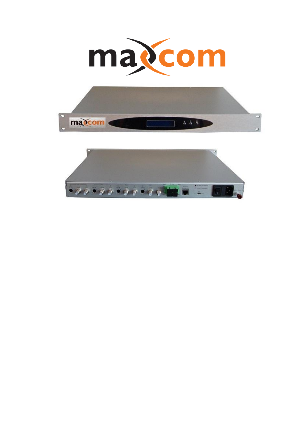
The MX4RR –LI reverse optical receiver is an indoor 1U rack structure with
natural ventilation cooling. The working environment temperature is 0℃~50℃,
the nominal power is AC 110/220V, 50/60Hz, power fuses is 1A, 20mm long.
Receiver’s optical input port is SC/ APC connector (FC/ APC optional), high
quality APC connector is recommended.
3、Energized Inspection
Necessary test tools should be used for set-up. Such as a digital multimeter, SC/
APC optical fiber jumper, optical power meter, RF signal level meter, spectrum
analyzer, etc.
The optical power transmitted from the reverse laser transmitter, to the reverse
optical receiver should be designed and set up to target the optical receiver input
power range. Before connecting the optical signals to the optical receiver, you should
use an optical power meter to verify the optical level, the level should not exceed
0dBm, between 0dBm~-20dBm is preferable.

4、 Mode Selection Switch
Optical receiver’s rear panel is equipped with a mode selector switch. The switch
sets the status to determine the receiver’s working mode—— RFoG (high sensitivity)
mode, or Normal mode.
·RFoG Low power receive pattern, the received optical power range is
-20~-5dBm
·Normal Normal power receive pattern, the received optical power range is
-5~0dBm, with AGC function.
5、 Button
The front panel has 3 buttons:
“▲”: turns the page in the initial state; increases output power/ decreases the
amount of attenuation in the channel status, 1dB step, the minimum amount of
attenuation is 0dB.
“▼”: turns the page in the initial state; decreases output power/ increases the
amount of attenuation, 1dB step, the max amount of attenuation is 30dB.
“
TR R 7 8 0 0 O P TICA L R ETU R N R ECEIV ER
L
”: the enter key, turns the page
6、 User Note:
The laser receiver is precise opto-electronic equipment, the user should follow
the operating standards strictly when using and operating. Improper operation may
cause laser receiver damage or personal injury.
Laser is harmful to eyes, to avoid retina damage, never look into the optical
output port directly.
The optical connector and fiber jumpers performance has significant impact on
the laser transmission link index, MX4RR –LI low power return optical receiver’s
optical input port adopts high-quality SC/ APC connectors, you must choose the same
type high quality active optical fiber connector in order to ensure the system stability
and reliability.
7、 Fault Handling
1) If the he measured value of the optical power, which is transmitted from the
transmitter to the receiver, measured by optical power meter is low. If this
occurs, you may first inspect the optical transmitter’s output power. If the
optical transmitter’s output power is normal, then a fault may exist in the
transmission link. Fiber optics, fusion and related active optical fiber
equipment.
2) If optical output power is within proper operating window of the transmitter and
calculated loss budget, but the receiver output RF signal level is below the
normal value. Common issues may prevent the optical link from operating
properly, the transmitter output optical connector may be polluted/dirty or
poorly spliced, the receiver input connector is polluted and so on. These will
cause the optical receiver power to be too low. Check the optical transmission
link carefully.
3) If the input optical level is good, the transmitter is working properly, but the
receiver’s output RF signal level is higher than the normal value. Common
reasons for such breakdown may be the receiver input optical power is too

high or the transmitter’s modulation index has increased. If affected by this
situation, you may need to adjust the attenuator on the optical receiver, adjust
the receiver output power to appropriate level.
This equipment should be installed and serviced by personnel familiar
with RF and optical equipment, and trained for laser safety!
Provided by: Mega Hertz 800-883-8839 [email protected] www.go2mhz.com
Table of contents
Other Maxcom Receiver manuals