Altinex VGA Line Receiver DA103-217 User manual

DA103
DA103DA103
DA103-
--
-217 VGA Line Receiver
217 VGA Line Receiver217 VGA Line Receiver
217 VGA Line Receiver
User’s Guide
400-0522-004
1
Welcome!
We greatly appreciate your purcha e of the DA103-217 VGA Line Receiver.
We are ure you will find it reliable and imple to u e. Superior performance
for the right price, backed by olid technical and cu tomer upport i what
ALTINEX ha to offer.
We are committed to providing our cu tomer with
Signal Management Solution
®
to the mo t demanding audiovi ual
in tallation at competitive pricing and we welcome you to join the rank of
our many ati fied cu tomer throughout the world.
1. Precautions and Safety Warnings
Plea e read thi manual carefully before u ing your DA103-217 and keep it
handy for future reference. The e afety in truction are to en ure the long
life of your DA103-217 and to prevent fire and hock hazard . Plea e read
them carefully and heed all warning .
1.1 General
•Do not open the unit or power upply, there are high-voltage
component in ide.
•There are no u er erviceable part in ide. Qualified ALTINEX ervice
per onnel mu t perform all ervice on the DA103-217.
1.2 Handling
•Place the DA103-217 in a dry area away from du t and moi ture.
•To prevent fire or hock, do not expo e thi unit to water or moi ture.
Do not place the DA103-217 in direct unlight, near heater , or
heat-radiating appliance , or near any liquid. Expo ure to direct
unlight, moke, or team can harm internal component .
•Handle the unit carefully. Dropping or jarring can cau e damage.
•Do not pull any cable that are attached to the DA103-217.
•Do not place heavy object on top of the DA103-217.
•If the DA103-217 i not u ed for an extended period, di connect the
adapter from the wall to avoid fire, hock, and power lo .
1.3 Cleaning
•Unplug the DA103-217 adapter before cleaning.
•Clean only with a dry cloth. Never u e trong detergent or olvent
uch a alcohol or thinner. Do not u e a wet cloth or water to clean the
unit. Do not open the unit to clean.
1.4 FCC Notice
•Thi device complie with Part 15 of the FCC Rule . Operation i
ubject to the following two condition : (1) Thi device may not cau e
harmful interference, and (2) thi device mu t accept any interference
received, including interference that may cau e unde ired operation.
•Thi equipment ha been te ted and found to comply with the limit for
a Cla A digital device, pur uant to Part 15 of the FCC Rule . The e
limit are de igned to provide rea onable protection again t harmful
interference when the equipment i operated in a commercial
environment. Thi equipment generate , u e , and can radiate radio
frequency energy and if not in talled and u ed in accordance with
in truction found herein, may cau e harmful interference to radio
communication . Operation of thi equipment in a re idential area i
likely to cau e harmful interference in which ca e the u er will be
required to correct the interference at hi own expen e.
•Any change or modification to the unit not expre ly approved by
ALTINEX, Inc. could void the u er’ authority to operate the
equipment.
2. Installation Procedures
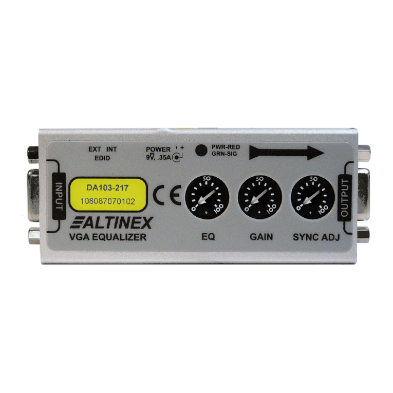
Step 1. Determine if the computer need to receive available video re olution from the di play device or from the internal memory of the DA103-217. Set the
EDID witch to INT for u ing the DA103-217 internal memory or EXT to u e the di play re olution . The witch i located on the ide of the unit and
i acce ible through a rectangular opening.
Step 2. U e the video cable provided and connect one end to the di play and the other end to the output of the DA103-217.
Step 3. Connect the long cable from the ource to the DA103-217 video input.
Step 4. Apply power to the DA103-217 u ing the adapter provided. The Power/Signal Pre ent LED i RED if there i power
and GREEN if a ignal i pre ent.
Step 5. Set the adju tment potentiometer a follow :
EQ= Minimum (full CCW) GAIN = Minimum (full CCW) SYNC ADJ = Midway (50%)
Step 6. If the image i vi ible, tart by adju ting the EQ until the image i clear. A 250 ft (76 m) cable require near maximum equalization. If there i no
image, tart by lowly increa ing the SYNC ADJ. Stop adju ting when the image i vi ible.
Step 7. While viewing the image on the di play, fine-tune the image u ing the EQ and GAIN adju tment .
Step 8. Next, fine-tune the SYNC ADJ for the be t image/ creen po ition.
Step 9. The DA103-217 i now operational.
3. Limited Warranty/Return Policies
Plea e ee the ALTINEX web ite at www.altinex.com for detail on warranty and return policie .

DA103
DA103DA103
DA103-
--
-217 VGA Line Receiver
217 VGA Line Receiver217 VGA Line Receiver
217 VGA Line Receiver
User’s Guide
400-0522-004
2
4. Technical Specifications
Specification are ubject to change. See www.altinex.com for up-to-date information.
Features/Description DA103-217
Inputs
VGA 15-pin HD F (1)
Output
Video 15-pin HD F (1)
Power
DC Power (adapter) DC power jack (1)
Compatibility
Signal Types RGB, RGsB, RGBS,
RGBHV, YPbPr
Video Signal
Resolutions VGA through UXGA
480p through 1080i
EDID Memory Selectable for
internal or external
Accessories Included
Video Cable VGA to Display, 18 in
Power Adapter +9VDC, 1.1 A
Optional Accessories
Ultra-Thin VGA
Video Cable CB3000PV Series
Table 1. DA103-217 General
Mechanical DA103-217
Material 0.091 in Al
Color Black
Height 0.8 in (20 mm)
Width 3.9 in (99 mm)
Depth 1.6 in (41 mm)
Weight 0.2 lb (0.1 kg)
Shipping Weight (approx.) 1.0 lb (0.5 kg)
T°Operating 10°C-35°C
T°Maximum 0°C-50°C
Humidity 90%non-condensing
MTBF (calculations) 40,000 hrs (min.)
Table 2. DA103-217 Mechanical
Electrical DA103-217
Video Adjustments
Gain 0 to 3 dB
Sync Threshold 0.5 to 4.5 V
Equalization Up to 250 ft (76 m)
Input
Video Signal 1.4 Vp-p max
Video Impedance 75 ohms
Sync Signal TTL (+/-)
Sync Impedance 10 kohms
Sync Threshold 4.5 V nominal
Output
Video Gain 0 dB +/- 0.5 dB nominal
Video Impedance 75 ohms
Sync Signal TTL (+/-)
Sync Impedance 22 ohms
Sync Polarity Plus or Minus
(follows input)
Power Consumption
+9V 250 mA
Total Power 2.25 W max
Table 3. DA103-217 Electrical

DA103
DA103DA103
DA103-
--
-217 VGA Line Receiver
217 VGA Line Receiver217 VGA Line Receiver
217 VGA Line Receiver
User’s Guide
400-0522-004
3
5. About Your DA103-217
•Recover ignal after 250 ft (76 m) of ultra-thin VGA cable
•Equalization/gain adju t for image optimization
•Compact and turdy
•AGC control for ync re toration
•Internal or external EDID election
The DA103-217 i a VGA line receiver for long cable run u ing RGBHV or VGA type cable . It connect to the di play end and allow adju tment of video
equalization, gain, and ync thre hold to recover degraded analog ignal and improve video quality. The DA103-217 can compen ate for up to 250 ft (76 m) of
ultra thin VGA cable.
Cable run over 75 ft (23 m) probably need and hould have thi line receiver. In application without the DA103-217, cu tomer may complain about image
mearing, blurrine , and other di tortion . The DA103-217 eliminate mearing and other di tortion while making letter and graphic harp and legible.
It i recommended to in tall the DA103-217 at the di play end for be t re ult . It mall ize allow ea y in tallation behind a di play or in a ceiling pace while
the metal enclo ure provide trength and protection for long life and reliability.
Other feature include a ignal pre ent indicator that how when a ignal i pre ent, AGC control for ync recovery, and internal or external EDID election for
proper computer etting to match di play re olution.
POWER/SIGNAL PRESENT
INPUT
VIDEO
INPUT
VIDEO
GREEN = SIGNAL PRESENT
RED = POWER
EDID SWITCH
INTERNAL/EXTERNAL POWER 9V, 0.25A

DA103
DA103DA103
DA103-
--
-217 VGA Line Receiver
217 VGA Line Receiver217 VGA Line Receiver
217 VGA Line Receiver
User’s Guide
400-0522-004
4
6. Application Diagrams
Diagram 1: Typical Setup

DA103
DA103DA103
DA103-
--
-217 VGA Line Receiver
217 VGA Line Receiver217 VGA Line Receiver
217 VGA Line Receiver
User’s Guide
400-0522-004
5
Diagram 2: Internal View

DA103
DA103DA103
DA103-
--
-217 VGA Line Receiver
217 VGA Line Receiver217 VGA Line Receiver
217 VGA Line Receiver
User’s Guide
400-0522-004
6
7. Operation
The DA103-217 will operate ucce fully a long a cable are attached
properly and other technical pecification are followed.
The adju tment on the DA103-217 Line Receiver are available to
fine-tune the output image and to compen ate for error induced by cable
quality, cable length, and variation in equipment.
7.1 Adjustments
7.1.1 Eq
Video equalization i provided to fine-tune the di played image on the
remote di play. Typically, for hort cable run the equalization will be
et to near minimum. Cable length up to 250 ft (76 m) will require
near maximum equalization.
7.1.2 Gain
Video gain i provided to re tore ignal level and brightne to the
remote di play. Typically, thi adju tment i made after the
equalization ha been et.
7.1.3 Sync Adj
The ync thre hold adju tment allow change to be made in the ync
proce ing circuitry and to help recover and compen ate for degraded
ignal . Alway tart thi adju tment with the potentiometer et to the
50% po ition and make adju tment in mall increment .
8. Troubleshooting Guide
We have carefully te ted and found no problem in the upplied
DA103-217; however, we would like to offer ugge tion for the following:
8.1 LED is Not Red
The LED hould be ON and RED when power i applied and there i no
video ignal pre ent. If the LED i ON and GREEN, the unit i receiving
power and a SYNC ignal.
Cau e 1: No AC power.
Solution:
Verify the adapter i plugged into a working AC outlet and
that the outlet ha power.
Cau e 2: Adapter i not plugged into DA103-217.
Solution:
Verify the DC power plug coming from the AC adapter i
plugged all the way into the DA103-217.
Cau e 3: The DA103-217 ha a problem.
Solution:
If there i AC power to the adapter and the LED till doe not
turn on, call ALTINEX at (714) 990-2300.
8.2 LED is Not Green
Cau e 1: There i no power.
Solution:
Di connect the video input from the DA103-217 and verify the
LED i ON and RED indicating power i pre ent. Reconnect
the computer' video output. If the LED i till not GREEN ee
Cau e 2.
Cau e 2: There i no ync ignal.
Solution:
Verify the computer output i operating correctly by
connecting it directly to the local monitor. If the di play i
good, call ALTINEX at (714) 990-2300.
8.3 No Remote Image
Cau e 1: The ource ha a problem.
Solution:
Check the image on the local monitor and verify the quality i
good. If the local image i good, ee Cau e 2.
Cau e 2: Cable connection are incorrect.
Solution:
Make ure that cable are connected properly. Al o, make ure
that the continuity and wiring are good. If there i till no
image pre ent, ee Cau e 3.
Cau e 3: Video equalization required.
Solution:
Adju t the EQ potentiometer on the DA103-217.
In general, cable run le then 50 ft (15 m) require little or no
video equalization and hould be et to minimum to tart.
Cable run up to 250 ft (76 m) will require maximum
equalization.
8.4 Remote Image Quality is Poor
Cau e 1: The ource ha a problem.
Solution:
Check the image on the local monitor and verify the quality i
good. If the local image i good, ee Cau e 2.
Cau e 2 Poor ignal tran mi ion.
Solution:
Check the cable for continuity and make ure that
connection are wired properly to verify that there i good
ignal tran mi ion. If the image i till not correct, call
ALTINEX at (714) 990-2300.
Cau e 3: Video equalization required.
Solution:
Slowly adju t the EQ, GAIN, and SYNC ADJ potentiometer
on the DA103-217 while viewing the di play. If the image till
cannot be et correctly, call ALTINEX at (714) 990-2300.
Other manuals for VGA Line Receiver DA103-217
2
Table of contents
Other Altinex Receiver manuals

Altinex
Altinex DA1931CT User manual

Altinex
Altinex MULTI-TASKER MT103-123 User manual

Altinex
Altinex TP315-102 User manual

Altinex
Altinex INTERA DS801-111 User manual

Altinex
Altinex TP115-111 User manual

Altinex
Altinex VGA Line Receiver DA103-217 User manual

Altinex
Altinex MUSE MU600-001 User manual

Altinex
Altinex VGA Line Receiver DA103-217 User manual

Altinex
Altinex INTERA DS801-111 User guide

Altinex
Altinex DA1931CT User manual