Town ECODECK User manual

CHINESE WOK RANGE OWNER’S MANUAL
SECTION 1 INSTALLATION INSTRUCTIONS
When sold in the Commonwealth of Massachusetts this unit must be equipped with an interlock
to prevent operation only if the hood system is operational. Installation of the interlock is the
responsibility of the installer—it is not supplied by the factory.
WARNING
Improper installation, adjustment, alteration, service or maintenance can cause property damage, injury or death.
Read the installation, operating and maintenance instructions thoroughly before installing or servicing this equipment.
FOR YOUR SAFETY
Do not store or use gasoline or other flammable vapors and liquids in the vicinity of this or any other appliance.
IMPORTANT
Contact your local gas supplier for instructions if you smell gas near this equipment.
FOR COMMERCIAL USE ONLY
© Town Food Service Equipment Company, Inc. No part of this booklet or it’s illustrations may be copied or reproduced without written authorization from Town Food Service Equipment Co., Inc.
6/14
DO NOT DISCARD INSTRUCTIONS. THIS MANUAL MUST REMAIN WITH THE UNIT FOR FUTURE REFERENCE.
THIS EMERGENCY INFORMATION MUST BE PROMINENTLY DISPLAYED.
Town Food Service Equipment Company, Inc. 718/388-5650 outside New York State 800/221-5032
2
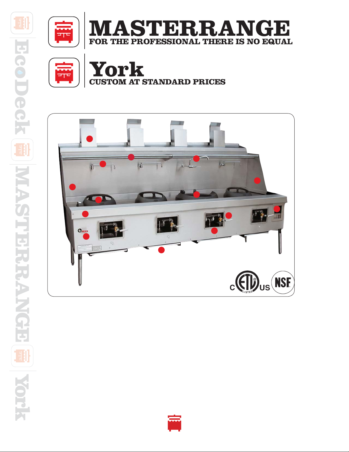
AREMOVABLE FLUE RISER CAP
B BACK SPLASH
CSWING FAUCET
D3 PIPE WOK COVER/STRAINER RACK
E MANUAL FAUCET
FSIDE SPLASH
G MANDARIN CHAMBER RING
HCANTONESE CHAMBER RING
I PLATE SHELF
J WATER WASH CONTROL VALVE
KDRIP TRAY
LPILOT LIGHT CONTROL VALVE
MKNEE OPERATED GAS VALVES
NFRONT ACCESS SINK (WASTE) BASKET
YORK AND MASTERRANGE PARTS IDENTIFICATION
A
B
G
J
I
E
F
K
H
D
L
M
N
C
_________________________________________________________________________________
_________________________________________________________________________________

EF-1 E-1 YF-1 Y-1 MF-1 M-
1
Town Food Service Equipment Company, Inc. 718/388-5650 outside New York State 800/221-5032
3
POSITIONING
1) Position crate in approximate location that the unit will occupy. Uncrate range and locate sealed cartons on
the range top containing the following accessories: (1) set of adjustable legs or casters if ordered; (1) drip pan
for each chamber; (1) extension chimney for each opening in return splash if your unit is equipped with a flue
riser; and (1) gas pressure regulator. Find the legs and set one leg by each range gusset into which it will be
inserted. Raise 1 end of the unit at a time; insert legs; and tighten set screws with ¼” Allen wrench. If your
range has flue risers, slip the extension chimney over each riser.
2) Range is now ready for final positioning. Carefully lift range into desired position to avoid damage to
adjustable legs. Clearances from combustible construction are 6” at rear and sides. Remove burner tie wires
and other packing materials. Check gas burners that may have shifted in transit and center them by eye if
required. Turn all gas valve lever handles to off (horizontal) position. Check air mixer alignment to gas burner
nipple and tighten set screws if necessary.
3) Clearances for noncombustible construction are the same as combustible clearances.
This range is for installation only on noncombustible floors.
INSTALLATION
• The gas supply line must be of adequate size to ensure maximum efficiency of the unit.
• The installation must conform with the National Fuel Gas Code, ANSI Z223.1, Natural Gas
Installation Code, CAN/CGA-B149.1 or the Propane Installation Code, CAN/CGA-B149.2, as applicable,
including:
a) The appliance and its individual shutoff valve must be disconnected from the gas
supply piping system during any pressure testing of that system at test pressures in
excess of
1
/2PSI (3.45 kPa).
b) The appliance must be isolated from the gas supply piping system by closing its
individual manual valve during any pressure testing of the gas supply piping system
at test pressures equal or less than 1
/2 PSIG (3.45 kPa).
• Local regulations governing gas appliance installations must be complied with.
• Equipment should be under hood with adequate ventilation.
STOCKPOT AND WOK TOP RANGE INSTALLATION INSTRUCTIONS
_________________________________________________________________________
_________________________________________________________________________
FOLLOW THESE INSTRUCTIONS CAREFULLY
INSTALLATION AREA MUST BE FREE AND CLEAR FROM COMBUSTIBLES
CONGRATULATIONS ON YOUR PURCHASE OF A ECODECK, YORK OR MASTERRANGE WOK RANGE
It will give you many years of trouble free use if it is properly used and maintained. Please call our customer service
department at 718/388-5650 if you have questions regarding equipment operation or care.
Your range has been carefully engineered and constructed with the best possible workmanship and materials to
provide many years of satisfactory service. Proper installation is vital if best appearance and performance is to be
achieved.
Town Food Service Equipment Company, Inc. 718/388-5650 outside New York State 800/221-5032
4
• The unit must be installed in an area or room with sufficient fresh air supply to ensure proper combustion.
• There must be adequate clearance for air openings into the combustion chamber.
• This equipment must be installed with adequate clearance for servicing and proper operation.
• This unit should be operated only with drip trays in place.
• Use of the supplied gas pressure regulator is mandatory.
• The front of the unit must be kept clear to avoid restriction of air supply for proper combustion.
• If your unit is supplied with casters, the installation shall be made with a connector that complies with the
standard for connectors for Movable Gas Appliances, ANSI Z21.69 or connectors for Moveable Gas
Appliances, CAN/CGA-6.16, and a Quick-Disconnect Device that complies with the standard for
Quick-Disconnect Devices for use with gas fuel ANSI Z21.41, or Quick-Disconnect Devices for use with
Gas fuel, CAN1-6.9, and adequate means must be provided to limit the movement of the appliance without
depending on connector and the Quick-Disconnect Device or its associated piping to limit the
appliance movement.
• If your unit is provided with casters on legs, the legs with locking casters must be installed in front of the unit.
An approved restraining device must be secured to the unit’s rear or side.
1) BURNERS AND FAUCETS
Remove any nylon hold-downs on the faucets. The burners may also have hold-downs and may have shifted
during shipping. Remove the nylon hold-downs and center the burner in the chamber. Tighten clamps as
necessary.
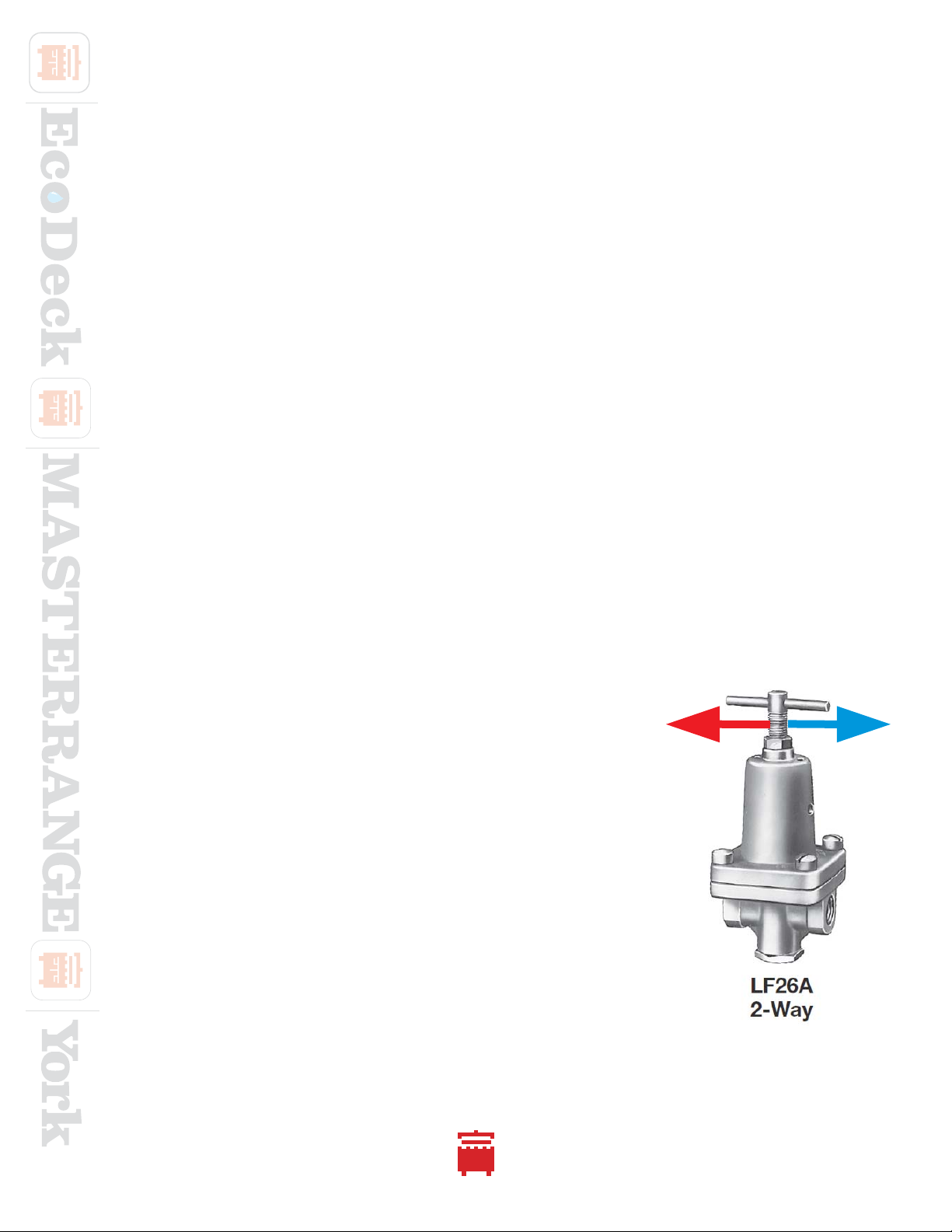
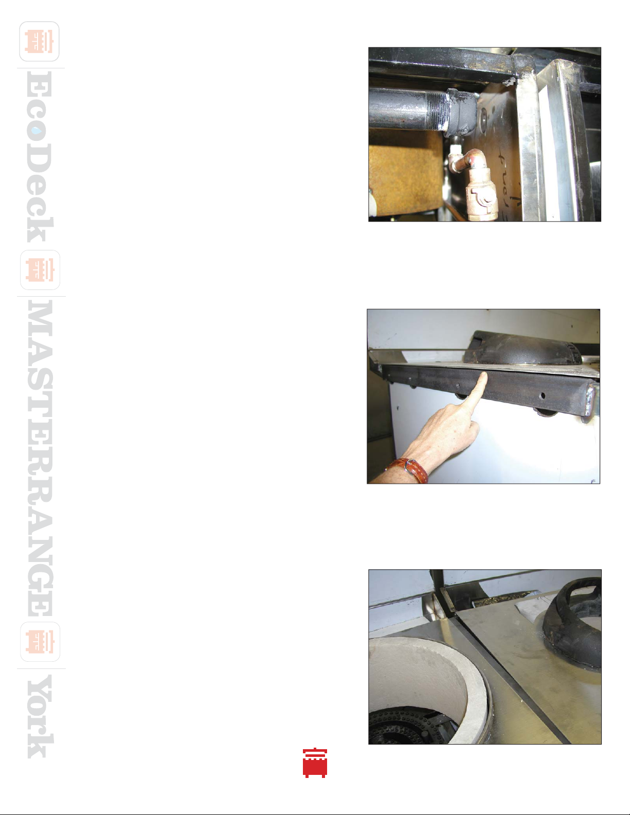
2) WATER-PRESSURE REGULATOR
This wok range has a pre plumbed water pressure regulator/ flow
restrictor. It is factory set for 50 PSI outlet. This is done to conserve water
and prevent water from the cooling spray bar from splashing over the
side of the range causing a “leak”. When installed, the water flow from
the cooling line and the faucets must be checked
for adequate flow. If the water pressure is low at the installation site the
regulator must be adjusted to increase the water flow. (Please refer to the
attached instruction sheet for information on how to adjust the regulator)
With spray bar valve on you should observe a constant flow of water
from spray bar that fully covers the
entire deck. This applies to all rear and front gutter units except EcoDeck
Note: if water pressure is high, the regulator may need to be adjusted to
LOWER the pressure.
3
IMPORTANT INFORMATION ABOUT WATER AND GAS SETUP
_________________________________________________________________________
_________________________________________________________________________
Clockwise more pressure counterclockwise less pressure

EF-1 E-1 YF-1 Y-1 MF-1 M-
1
Town Food Service Equipment Company, Inc. 718/388-5650 outside New York State 800/221-5032
5
3) WATER AND DRAIN
Check that all faucets work. If it is a Chinese style swing faucet, move the faucet perpendicular to the backsplash
to check for water flow. Turn on the water wash and verify that water flows and washes the entire deck surface.
Verify that the water flow covers the entire top deck and the backsplash- if a front gutter, waterfall backsplash
design. Level as necessary to ensure even water flow across the deck by adjusting bullet legs to position and
control pitch of deck. Refer to item # 2 if water flow needs to be adjusted due to pressure.
4) PILOTS
After the unit has been connected by the licensed plumber and has passed local inspection, turn gas on and
light all of the pilots. In a standing pilot, light each pilot and adjust flame using the pilot gas valve supplied for
each chamber. The pilot valve is the small brass fitting with a small brass hex screw and is located on each
manifold burner gas riser. Using a jeweler’s screwdriver, turn clockwise to decrease the flame and counter
clockwise to increase the flame. Do not remove the screw. If a safety pilot, there will be a small control in the
front panel for each chamber with a red button. Follow the instructions in the owner’s manual for startup using
safety pilots. The burners will not light if the safety pilots are not lit first.
5) PILOT SAFETY SYSTEM
The Pilot safety system utilizes a thermocouple. The thermocouple connection must be clean and tight. This unit
is shipped with the thermocouple(s) connected and properly tightened. Connection cannot be too tight or the
grey bulb (positive connection) will break off. Check that the grey bulb is free of corrosion, clean with fine grit
sandpaper if necessary. Hand tighten the hex fitting, then using a wrench tighten the hex nut an additional ¼
turn clockwise. If you over tighten the hex nut the bulb will break off.
6) GAS REGULATOR
The supplied appliance regulator has a maximum continuous rated input of 15” WC (approx. 0.5psig). The
supplied regulator must be installed on all Town wok ranges. Do not overpressure the regulator. If your natural
gas system is a 2-5 PSI system you need to have a 1st stage line regulator (supplied by others) installed
upstream of our appliance
7) GAS FEED
If the manifold piping and final connection piping are not properly sized the equipment will not function at
optimal levels. Consult with your plumber or LPE to insure that the pipe sizing is correct. We do not recommend
Flex type (quick disconnect) hoses for use with the woks. If selected, the flex should be sized to flow the rated
gas input capacity. The maximum flex hose length should be 36” and be without any swivel connectors.

Town Food Service Equipment Company, Inc. 718/388-5650 outside New York State 800/221-5032
6
figure 2
PILOT VALVE
figure 1
SAFETY PILOT BUTTON
put lit match to pilot
burner, depress and
hold red button
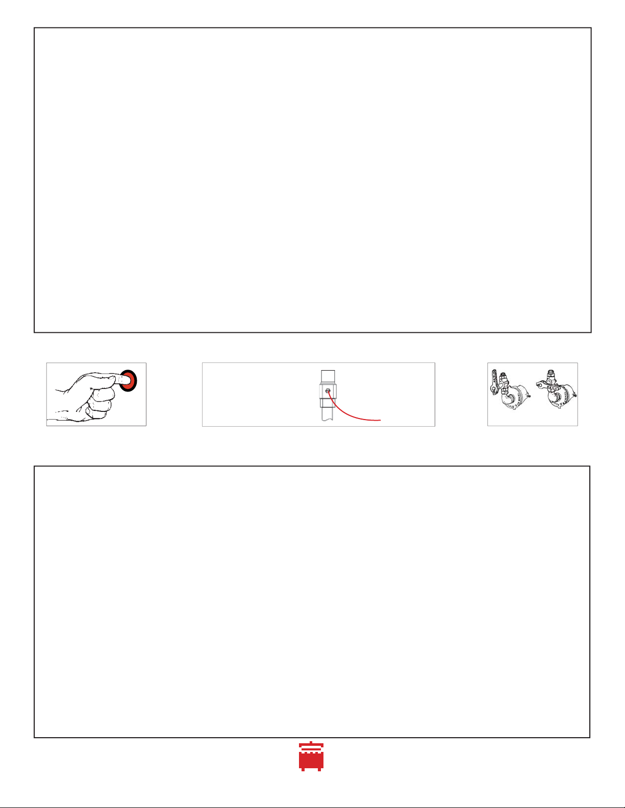
UNITS WITH SAFETY VALVES
LIGHTING AND SHUT DOWN INSTRUCTIONS
Always follow these lighting and shutdown instructions when operating your unit.
A 5 minute complete shutoff period is required before lighting or relighting pilot. See diagrams above.
1) Check that all gas valves on the unit are turned off (lever handles in horizontal position) before turning
on main gas line. Check for leaks using soapy water or other suitable leak detector.
DO NOT USE OPEN FLAME FOR TESTING
2) Main burner valve should be in offposition (figure 3). Place a burning match by the pilot burner in the
combustion chamber of the range. Depress red safety pilot button on (figure 1) and light pilot.
3) The pilot should light. Continue to hold the button for 1 minute or until the pilot stays lit.
TEMPORARY AND EXTENDED SHUTDOWN
For temporary shut down turn all burner valves to off position.
For an extended period of time, turn all burner valves off and also turn off gas supply to the range.
ON position
turn clockwise
until screw
cannot be turned
OFF position
turn counter-clockwise
pilot screw OFF position
ON position
UNITS WITHOUT SAFETY VALVES
LIGHTING AND SHUT DOWN INSTRUCTIONS
Be sure that all piping is gas tight and that all air is purged from lines. With main burner valve in off position
(figure 3), using a screw driver turn pilot screw counter clockwise to on (figure 2) and light pilot located in the
combustion chamber. Make sure the pilot stays lit.
All units are equipped with fixed orifices which cannot be adjusted for gas flow. Only ring burners have
adjustable air mixers to adjust the air/gas mixture.
Turn right hand burner valve to full on position (figure 3) and adjust air shutter until proper blue flame is
burning on both inner rings. Repeat operation for left hand valve only if your range is equipped with 3
ring burners.
SHUTDOWN
Turn burner valves to off position (figure 3) and turn the pilot screw clockwise (figure 2) until it cannot be
turned further. Repeat this step for each chamber.
INSTALLATION AREA MUST BE FREE AND CLEAR FROM COMBUSTIBLES
LOCAL SAFETY CODES SHOULD BE COMPLIED WITH IN RESPECT TO FIRE AVOIDANCE
AIR SHUTTER
(ring burners only)
figure 3
MAIN BURNER VALVE
4

EF-1 E-1 YF-1 Y-1 MF-1 M-
1
Town Food Service Equipment Company, Inc. 718/388-5650 outside New York State 800/221-5032
7
gutter
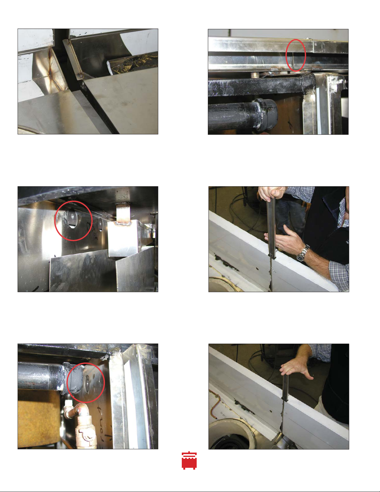
Some installations require the backsplash to be removed so the range can fit through a 34” door.
Town ranges are manufactured with removable backsplashes. Follow these steps to remove backsplash:
1) Loosen union at backsplash (figure 1).
2) Remove sidesplash bolts and lower backsplash (figure 2).
3) Faucet manifold must be placed below gutter (figure 3)
4) Lower backsplash until sidesplash clears gutter (figure 4).
5) Sidesplash may be removed. Range will fit through 34” opening (figure 5).
6) Reinsert sidesplash and backsplash into gutter. Ensure backsplash “J”hooks in to the gutter “J”(figure 6).
7) Raise backsplash, making sure it is locked into the gutter “J”(figure 7).
8) When raised, the gutter and backsplash should be aligned. Bolt side splashes to body (figure 8).
figure 1
figure 4
figure 7
figure 6
figure 8
figure 3
gutter “J”
figure 5
figure 2
backsplash “J”
faucet
manifold
gutter
BACKSPLASH REMOVAL AND REINSTALLATION
_________________________________________________________________________________
_________________________________________________________________________________
Town Food Service Equipment Company, Inc. 718/388-5650 outside New York State 800/221-5032
8
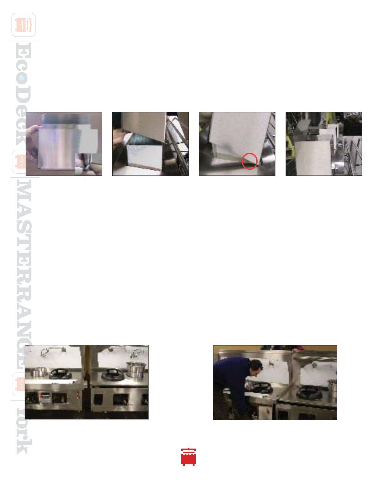
Ranges with optional Flue Risers have stainless steel extensions that cover the tops of the flue risers.
Locate the parts in the boxed marked “RANGE ACCESSORIES”.
1) Take assembled flue collar and turn with kink to rear (figure A).
2) Place flue collar on top of chimney extension as illustrated (figure B).
3) Catch front return beneath slot in backsplash (circled in figure C).
4) Snap kinked end into slot (figure D).
figure 1 figure 2
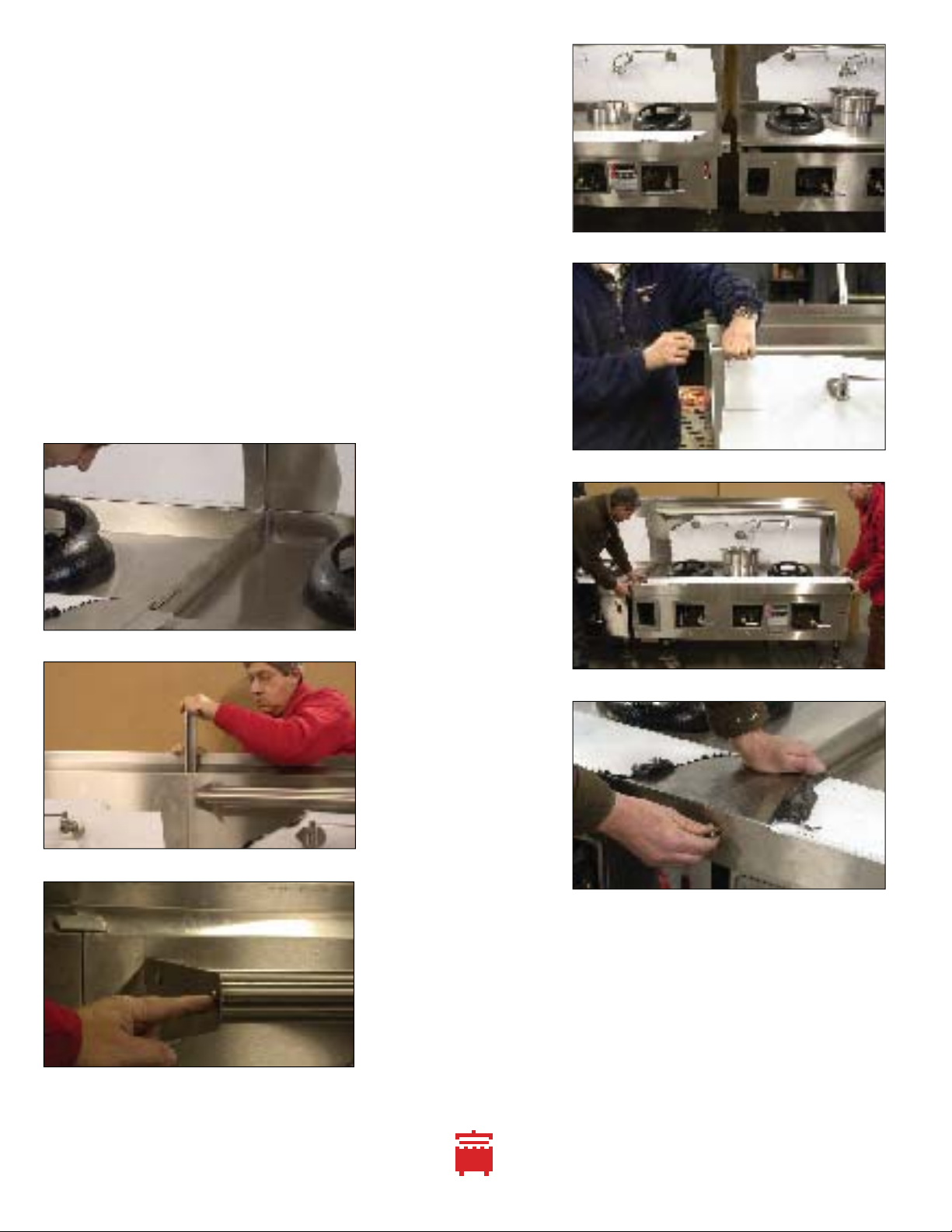
The optional field joint joins two or more ranges. It must be ordered when the ranges are built. It cannot be
added to existing ranges. A butt field joint has a standing seam between ranges while a splice field joint gives a
smooth fit.
Each range has a vertical seam at the joint between the ranges. The backsplashes will be joined.
1) Uncrate the ranges and install legs onto the gussets. Secure legs with the gusset set screw.
2) Carefully locate the battery into final location. Align the sides to be joined. The battery was assembled at the
factory to assure good fit. Pitched floors will add difficulty to battery assembly (figures 1 and 2).
3) Align the backsplashes. It may necessary to level the range so the backsplashes meet at top. Insert and slide
down the “U”shaped joiner until it is level with the top of the backsplash (figures 3 and 4).
figure C figure D
figure Bfigure A
KINK
FLUE RISER EXTENSION INSTALLATION (NEW VERSION ON UNITS SHIPPED AFTER JUNE 2005)
_________________________________________________________________________________
_________________________________________________________________________________
FIELD JOINT INSTALLATIONS
_________________________________________________________________________________
_________________________________________________________________________________
BUTT FIELD JOINT INSTALLATION INSTRUCTIONS
_________________________________________________________________________________
_________________________________________________________________________________
EF-1 E-1 YF-1 Y-1 MF-1 M-
1
Town Food Service Equipment Company, Inc. 718/388-5650 outside New York State 800/221-5032
9
4) Install the stainless tubular wok cover rack.
Male and female ends mate to become a
continuous length. Remove the bolts from the
brackets and install the tubing with threaded
ends. Use the bolts removed from the brackets
at the endsplashes. (figures 5, 6 and 7).
5) The range position may have to be adjusted
to align the bolt holes in the serving shelf with
the tapped holes provided for them (figures 8
and 9).
6) Pitch the range using the adjustable bullet feet
so that water flows off the top of the range.
7) Connections can be made by authorized
personnel. Each range has gas, waste and
water connections.
figure 9
figure 4
figure 8
figure 3
figure 5
figure 7
figure 6
Town Food Service Equipment Company, Inc. 718/388-5650 outside New York State 800/221-5032
10
figure 1
figure 2
figure 3
Range decks have a “tongue and groove”so there is no
standing seam between range decks. The decks and
backsplashes are joined. The gutters are separate but interlock.
1) Uncrate the ranges and place them on pallet jacks.
Be careful to position jacks away from drip pan guides.
2) Install the legs onto each range.
Secure legs with the set screw in the gusset.
3) Remove the front body panels. Figure 1 shows a
detail of front right corner of a range with the
body front panel removed.
4) Carefully move the ranges to their final location.
Position the ends to be joined next to each other.
The battery was assembled at the factory to
assure good fit. Pitched floors will add difficulty to
battery assembly.
5) Generously apply silicon to the groove below the
stainless steel deck. Apply additional silicon to the
tongue of the other range that will fit into this groove.
Figure 2 shows the groove.
6) Insert the tongue into the groove and slide the ranges
together as shown in figure 3.
7) Be certain that the range with an extension on its
gutter overlaps the gutter of the adjoining range as
shown in figure 4.
8) Locate the bolt holes in the range body as shown above
in figures 4 and 5 and bolt the range bodies together.
9) Silicon the front seam of range decks in the circled area
of figure 6.
10) Align the backsplashes. It may necessary to level the
range so the backsplashes meet at top. Insert and slide
down the
“U”shaped joiner until it is level with the top
of the backsplash. See figures 7 and 8.
11) Install the three stainless steel tubes of the wok cover
rack. Note—there are male and female ends that mate
to become a continuous length.
12) Pitch the range using the adjustable bullet feet so that
water flows off the top of the range.
8
SPLICE FIELD JOINT INSTALLATION INSTRUCTIONS
_________________________________________________________________________________
_________________________________________________________________________________
SPLICE FIELD JOINT INSTALLATION INSTRUCTIONS
_________________________________________________________________________________
_________________________________________________________________________________
EF-1 E-1 YF-1 Y-1 MF-1 M-
1
Town Food Service Equipment Company, Inc. 718/388-5650 outside New York State 800/221-5032
11
figure 8
figure 9
figure7
figure 4
figure 5
figure 6
9

CHINESE WOK RANGE OWNER’S MANUAL
SECTION 2 OPERATING
AND MAINTENANCE INSTRUCTIONS
When sold in the Commonwealth of Massachusetts this unit must be equipped with an interlock
to prevent operation only if the hood system is operational. Installation of the interlock is the
responsibility of the installer—it is not supplied by the factory.
WARNING
Improper installation, adjustment, alteration, service or maintenance can cause property damage, injury or death.
Read the installation, operating and maintenance instructions thoroughly before installing or servicing this equipment.
FOR YOUR SAFETY
Do not store or use gasoline or other flammable vapors and liquids in the vicinity of this or any other appliance.
IMPORTANT
Contact your local gas supplier for instructions if you smell gas near this equipment.
© Town Food Service Equipment Company, Inc. No part of this booklet or it’s illustrations may be copied or reproduced without written authorization from Town Food Service Equipment Co., Inc.
2/13
DO NOT DISCARD INSTRUCTIONS. THIS MANUAL MUST REMAIN WITH THE UNIT FOR FUTURE REFERENCE.
THIS EMERGENCY INFORMATION MUST BE PROMINENTLY DISPLAYED.
EF-1 E-1 YF-1 Y-1 MF-1 M-
1
Town Food Service Equipment Company, Inc. 718/388-5650 outside New York State 800/221-5032
13
figure 2
PILOT VALVE
figure 1
SAFETY PILOT BUTTON
UNITS WITH SAFETY VALVES
LIGHTING AND SHUT DOWN INSTRUCTIONS
Always follow these lighting and shutdown instructions when operating your unit.
A 5 minute complete shutoff period is required before lighting or relighting pilot. See diagrams above.
1) Check that all gas valves on the unit are turned off (lever handles in horizontal position) before turning
on main gas line. Check for leaks using soapy water or other suitable leak detector.
DO NOT USE OPEN FLAME FOR TESTING
2) Main burner valve should be in offposition (figure 3). Place a burning match by the pilot burner in the
combustion chamber of the range. Depress red safety pilot button on (figure 1) and light pilot.
3) The pilot should light. Continue to hold the button for 1 minute or until the pilot stays lit.
TEMPORARY AND EXTENDED SHUTDOWN
For temporary shut down turn all burner valves to off position.
For an extended period of time, turn all burner valves off and also turn off gas supply to the range.
ON position
turn counter-clockwise until
screw cannot be turned
DO NOT REMOVE SCREW
OFF position
turn clockwise
pilot screw ON position
OFF position
UNITS WITHOUT SAFETY VALVES
LIGHTING AND SHUT DOWN INSTRUCTIONS
Be sure that all piping is gas tight and that all air is purged from lines. With main burner valve in off position
(figure 3), using a screw driver turn pilot screw counter clockwise to on (figure 2) and light pilot located in the
combustion chamber. Make sure the pilot stays lit.
All units are equipped with fixed orifices which cannot be adjusted for gas flow. Only ring burners have
adjustable air mixers to adjust the air/gas mixture.
Turn right hand burner valve to full on position (figure 3) and adjust air shutter until proper blue flame is
burning on both inner rings. Repeat operation for left hand valve only if your range is equipped with 3
ring burners.
SHUTDOWN
Turn burner valves to off position (figure 3) and turn the pilot screw clockwise (figure 2) until it cannot be
turned further. Repeat this step for each chamber.
INSTALLATION AREA MUST BE FREE AND CLEAR FROM COMBUSTIBLES
LOCAL SAFETY CODES SHOULD BE COMPLIED WITH IN RESPECT TO FIRE AVOIDANCE
figure 3
MAIN BURNER VALVE
AIR SHUTTER (ring burners only)

Town Food Service Equipment Company, Inc. 718/388-5650 outside New York State 800/221-5032
14
1) GAS VALVE
Turn on the “L” handle gas valve using your knee or hand. The valve is fully open when the valve is pointin
straight up at the 12 o’ clock position.
Jet type burners have only one valve per chamber.
For a three ring burner there is a master “L” valve and two shorter straight
handle valves. The “L” valves controls the gas flow for both sub valves, while
each sub valve controls either the inner or outer ring. Turn on the main
“L” valve and then set the two sub valves for the flame desired. You can
leave them at this setting and use the “L” valve to turn the burner on and off.
When the valve(s) are fully open most if not all of the jet tips or port orifices
should light. Do not be concerned they all do not light immediately. The
burners need the backpressure of the wok for all the jets to light.
2) WATER AND DRAIN
When the wok is in operation be sure that the water cooling line is running. Failure to do so will cause the deck
top to overheat and possibly warp. For a standard rear gutter unit, the water will wash from the front to the back
(and from the top of the backsplash if a waterfall backsplash option is included). For a front gutter unit, the water
will flow from the top of the backsplash to the front of the unit.
3) SHUTDOWN
At the end of service shut off all the burners, but leave the water on for several minutes, to wash away remaining
food scraps and cool the unit. Leave both standing and safety pilots lit.
If equipment requires service, contact your authorized gas service company to perform necessary repairs.
Check the flue riser monthly to be sure it is free of obstructions. Be sure to clean the air mixers and orifices of ring
burners once a year. Jet and shield tip burners must be serviced more often as they become clogged more easily.
This service must be performed by a qualified gas service company.
Range should be cleaned each evening with grease dissolver and rinsed well. It will prevent grease
accumulation and keep the unit clean and sanitary.
If unit is supplied with casters, there should be a restraint on the appliance to limit its movement.
If disconnection of the restraint becomes necessary, it is imperative that the restraint be reconnected after the
appliance is returned to its originally installed position.
IMPORTANT INFORMATION ABOUT WATER AND GAS OPERATION
_________________________________________________________________________________
_________________________________________________________________________________
MAINTENANCE AND CARE
_________________________________________________________________________________
_________________________________________________________________________________
“L” handle valves
straight handle valves
EF-1 E-1 YF-1 Y-1 MF-1 M-
1
Town Food Service Equipment Company, Inc. 718/388-5650 outside New York State 800/221-5032
15
12
MAINTENANCE AND CARE
_________________________________________________________________________________
_________________________________________________________________________________
THE FOLLOWING SERVICE SHOULD BE DONE ONLY BY A QUALIFIED GAS SERVICE TECHNICIAN
CHANGING THE PILOT LIGHT IN A CHAMBER WITH A RING BURNER OR SHIELD TIP BURNER
Shut off pilot valve. The pilot light is mounted on flexible tubing and can be raised. Using a 12mm open-ended
wrench, hold the center of the compression fitting below the pilot firm.
Using a 1
/2 ”wrench, unscrew the pilot from its brass fitting at bottom. Install the new pilot by reversing the above
procedure. Adjust the pilot flame at the pilot valve and be sure to check for gas leaks using a soapy solution.
CHANGING THE PILOT LIGHT IN A CHAMBER WITH A JET BURNER
Shut off pilot valve. Using a 12mm open-ended wrench, unscrew the pilot, remove and replace.
If a 12mm open-ended wrench is unavailable, a 1
/2 ”open end or adjustable wrench may suffice.
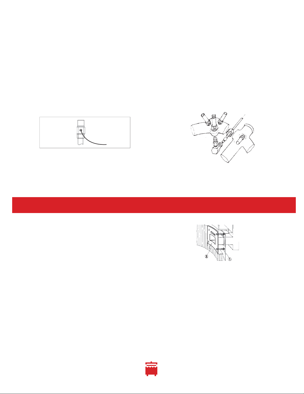
FLUE COLLAR REPLACEMENT (“F”MODELS)
The cast iron flue collar may deteriorate after considerable use. If deterioration is detected, we suggest you
contact your local service company for replacement parts and qualified service. If you must replace the flue col-
lar yourself, follow the instructions below:
SHUT OFF GAS TO RANGE BEFORE MAKING ANY ADJUSTMENTS
THE BURNER AND PILOT MUST BE REMOVED BEFORE REMOVING THE FLUE COLLAR
1) Remove old nuts behind range that secure flue collar (1).
2) Remove worn collars with pry bar (2).
Put new collar into place using provided hardware.
Re-cement chamber and replace burner and pilot.
PILOT VALVE
PILOT
FLUE COLLAR
ON position
turn clockwise
until screw
cannot be turned
OFF position
turn counter-clockwise
pilot screw

16
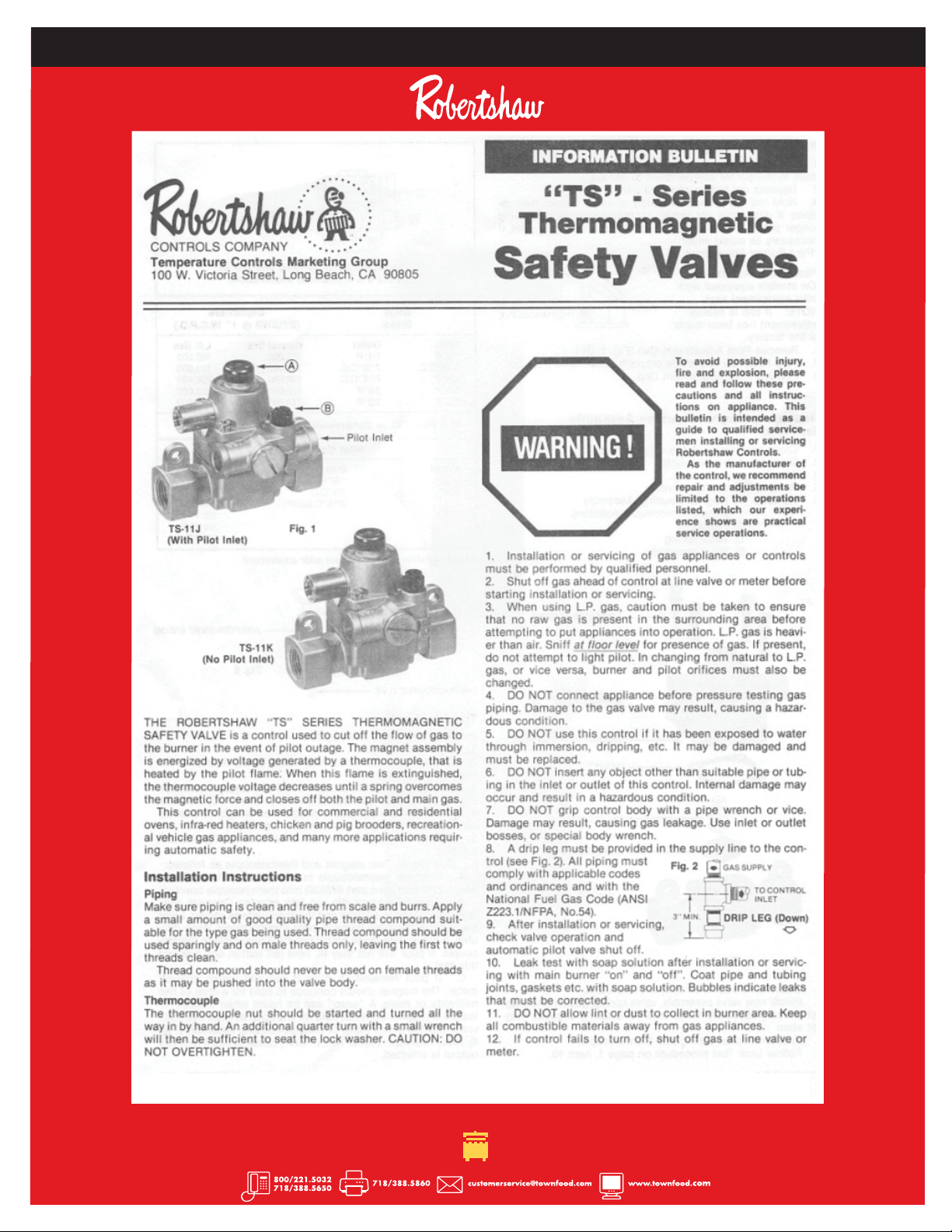
ROBERTSHAW PILOT SAFETY VALVE INFORMATION
_________________________________________________________________________________
_________________________________________________________________________________

17
ROBERTSHAW PILOT SAFETY VALVE INFORMATION
_________________________________________________________________________________
_________________________________________________________________________________
18
ROBERTSHAW PILOT SAFETY VALVE INFORMATION
_________________________________________________________________________________
_________________________________________________________________________________

EF-1 E-1 YF-1 Y-1 MF-1 M-
1
Town Food Service Equipment Company, Inc. 718/388-5650 outside New York State 800/221-5032
19
*please advise if chamber has a flue collar when ordering
ECODECK/YORK REPLACEMENT FIBER CERAMICS
number fits chamber interior dimension
225014N __ 13” _________ 11” (6 lbs.)
225016N __ 16” _________ 14” (7 lbs.)
225118N __ 18” _________ 16” (8 lbs.)
225020N __ 20” _________ 18” (9 lbs.)
225022N __ 22” _________ 20”(12 lbs.)
REPLACEMENT MASTERRANGE FIRE BRICKS
number description
225038 ____ 13” chamber brick set* (55 lbs.)
225042 ____ 16” chamber brick set* (65 lbs.)
225043 ____ 18” chamber brick set* (75 lbs.)
225044 ____ 20” chamber brick set* (85 lbs.)
225045 ____ 22” chamber brick set* (95 lbs.)
FLUE COLLAR AND RANGE CEMENT
Ranges without chamber rings often deteriorate
without insulating cement. Use 10 lbs. of cement to
recement a chamber.
number description
225009 ____ 20 lb. can dry cement
225010 ____ 100 lb. sack dry cement
225100 _____cast iron flue collar (15 lbs.)
RANGE DRIP PANS
number description
227113 _____galvanized drip pan__ 13” x 291
/4 ”(10 lbs.)
227114 _____galvanized drip pan__ 13” x 34” (12 lbs.)
227116 _____galvanized drip pan__ 161
/4” x 291
/4” (12 lbs.)
227117 _____galvanized drip pan__ 161
/4” x 34” (14 lbs.)
227120 _____galvanized drip pan__ 191
/4” x 291
/4 ”(15 lbs.)
227121 _____galvanized drip pan__ 191
/4” x 34” (17 lbs.)
227122 _____custom galvanized to customer’s sketch
227213 _____stainless drip pan ____ 13” x 291
/4 ”(10 lbs.)
227214 _____stainless steel drip pan 13” x 34” (12 lbs.)
227216 _____stainless drip pan ____ 161
/4” x 291
/4”(12 lbs.)
227217 _____stainless steel drip pan 161
/4” x 34” (14 lbs.)
227220 _____stainless drip pan ____ 191
/4” x 291
/4” (15 lbs.)
227221 _____stainless steel drip pan 191
/4” x 34” (17 lbs.)
227222 _____custom stainless to customer’s sketch
229821 _____small sink frame
229822 _____insert for small sink frame
229934 _____large sink frame
229935 _____insert for large sink frame
DRY CEMENT (20 LB. CAN)
DRIP PAN
SMALL SINK FRAME/INSERT FOR SMALL SINK FRAME
CERAMIC INSULATION
FIREBRICK INSULATION
CAST IRON FLUE COLLAR
13
RANGE PARTS
_________________________________________________________________________________
_________________________________________________________________________________

Town Food Service Equipment Company, Inc. 718/388-5650 outside New York State 800/221-5032
20
226916 CLEANING KIT
226800B
226917
226808-57
226800B
226808-60
226912
226822
226811
226807P
226806
16 TIP VOLCANO BURNERS
number description
226916N ____ 16 tip volcano, natural (12 lbs.)
226916P _____ 16 tip volcano, propane (12 lbs.)
226917 ______ replacement tip, natural gas
226918 ______ replacement tip, propane gas
226916C_____ replacement cover (4 lbs.)
226916N-CLNR _ natural gas cleaning kit
226916P-CLNR _ propane gas cleaning kit
226916B _____ cleaning brush
226808H_____ handle for tip cleaning drill
226808-60 ___ tip cleaning drill, natural gas
226808-73 ___ tip cleaning drill, propane gas
SHIELD TIP BURNERS
number description
226911N ____ 18 tip vertical shield, natural (10 lbs.)
226911P _____ 18 tip vertical shield, propane (10 lbs.)
226920N ____ 18 tip angle shield, natural (18 lbs.)
226920P _____ 18 tip angle shield, propane (18 lbs.)
226912 ______ shield tip, natural gas
226914 ______ shield tip, propane gas
226808-57 ___ shield tip cleaning drill, natural
226808-72 ___ shield tip cleaning drill, propane
226940 ______ shielded tip wrench
23 AND 32 TIP JET BURNERS
number description
226800N ____23 tip jet burner w/pilot, nat. (9 lbs.)
226800P _____23 tip jet burner w/pilot, prop. (9 lbs.)
226804N ____32 tip jet burner w/pilot, nat. (13 lbs.)
226804P _____32 tip jet burner w/pilot, prop. (13 lbs.)
226806N ____jet tip, natural, 1
/8”IPS, s/n 58071 & above
226807P _____jet tip, propane, 1
/8”IPS, s/n 58071 & above
226806 ______jet tip, natural, old type, small thread
226807 ______jet tip, propane, old type, small thread
226811 ______jet pilot, natural
226810 ______jet pilot, propane
226822 ______1
/8”IPS x 3
/8” compression elbow
226808-60 ___jet tip cleaning drill, natural
226808-72 ___jet tip cleaning drill, propane
226800B _____jet tip cleaning brush
226800 23 TIP JET BURNER
226920 ANGLE SHIELD TIP
226911 VERTICAL SHIELD TIP
226804 32 TIP JET BURNER
226916 16 TIP VOLCANO
226808H 226808-60
226916B
14
BURNERS AND PARTS
_________________________________________________________________________________
_________________________________________________________________________________
PILOT INCLUDED WITH BURNER. BELOW BURNERS ARE 1
/2”NPT INLET.
This manual suits for next models
2
Table of contents


