TOYODenki VF66 User manual
TOYO INTELLIGENT INVERTER
EIP66-Z Communication
Protocol Manual


3
Preface
Thank you very much for choosing our inverter optional board.
This manual describes the communication protocol of the optional board EIP66-Z designed for VF66 inverter.
Please read this manual thoroughly to use the EIP66-Z communication function properly.
This manual describes the EIP66-Z EtherNet/IP communication function. For the terminal block functions of
EIP66-Z board, wiring, switch settings and VF66 inverter settings, refer to "EIP66-Z Operating Instructions."
To use various functions according to intended use as well as the VF66 inverter functions, read the operating
instructions of VF66 inverter main unit or dedicated manual thoroughly before use.
The following shows the EtherNet/IP specification versions used by EIP66-Z.
Volume1:Edition 3.15 November 2013
Volume2:Edition 1.16 November 2013
4
Be Sure To Read This Before Use
Safety Notice
To use the EIP66-Z correctly, be sure to completely read this manual and all other attached documents before
installation, operation, maintenance, and inspection. You need to have a good knowledge of equipment, safety
information, and all notices before using the EIP66-Z. Read also the operating instructions of VF66 inverter
main unit thoroughly before use for safe operations.
In this manual, safety notices are ranked as "Danger," "Warning," and "Caution."
WARNING
When improper use may cause a dangerous situation, and death or serious
injury may result.
CAUTION
When improper use may cause a dangerous situation, medium-level or minor
injury may result, and only physical damage may result. However, it can
cause serious results depending on the situation. Cautions described in
this manual are all important. Be sure to observe them.
CAUTION [Installation]
Do not use the product if it is found damaged or deformed in unpacking.
It may cause failure/malfunction.
Do not put a flammable material near the product.
It may catch fire.
Do not give a shock to the product by dropping or toppling it.
It may cause failure/damage to the product.
Do not install an optional board with damage or missing part to perform operations.
It may cause injury.
WARNING [Wiring]
Check that the input power is turned off before wiring.
Otherwise, electric shock/fire may result.
After turning off the power, wait at least ten minutes before opening the inverter front cover.
Be sure to connect a ground wire.
Otherwise, electric shock/fire may result.
Let an electrical engineering technician do the wiring work.
Otherwise, electric shock/fire may result.
Be sure to install the main unit before wiring.
Otherwise, electric shock/fire may result.
5
CAUTION [Wiring]
Be sure to attach and lock the communication cable and connector.
Otherwise, failure/malfunction may result.
WARNING [Operation]
Be sure to attach the inverter front cover before turning on the input power.
Do not remove the cover while the inverter is energized.
Ignoring this may cause electric shock.
Do not operate the switch with wet hands.
Ignoring this may cause electric shock.
While the inverter is energized, do not touch the inverter terminal even when the inverter is stopped.
Ignoring this may cause electric shock.
Resetting an alarm with the operation signal input causes a sudden restart.
Perform resetting after making sure that the operation signal is off.
Otherwise, you may be injured.
The inverter operation setting is available from low to high speed. Check the allowable range of motor
or machine carefully before starting operation.
Otherwise, injury/failure/damage may result.
CAUTION [Operation]
Do not touch the inverter radiation fin or discharge resistor because it can be very hot.
Ignoring this may cause burn injury.
WARNING [Maintenance/inspection and part replacement]
Be sure to turn off the power before performing inspection.
Otherwise, electric shock/injury/fire may result.
Only the specified person must perform maintenance/inspection and part replacement.
Use an insulated tool for maintenance/inspection.
Otherwise, electric shock/injury may result.
CAUTION [Others]
Never modify the product.
Otherwise, electric shock/injury may result.
CAUTION [General cautions]
Some figures in this manual are shown with the cover or safety shield removed for the purpose of detailed
descriptions. However, for actual operations, be sure to attach the specified cover or safety shield and
follow the instructions in this manual.
Note that these safety precautions and specifications described in each manual are subject to change without
notice.

6
Contents
Be Sure To Read This Before Use ................................................................................................................................. 4
Safety Notice........................................................................................................................................................... 4
CHAPTER 1 Function Overview......................................................................................................................................... 7
CHAPTER 2 Function Specifications.............................................................................................................................. 8
2. 1 EtherNet/IP Communication Function Connector/Terminal Specifications.......................................... 8
2. 2 EtherNet/IP Communication Specifications............................................................................................... 8
2. 3 Device Profile................................................................................................................................................ 9
2. 4 Others................................................................................................................................................................ 9
CHAPTER 3 Communication Function Description....................................................................................................... 10
3. 1 Parameter Setting........................................................................................................................................ 10
3. 2 Speed Commanding Place Setting ............................................................................................................... 12
3. 3 I/O Assembly Instance Number Setting.................................................................................................... 13
CHAPTER 4 I/O Assembly ................................................................................................................................................ 14
4. 1 Standard I/O Assembly Data Attribute Format....................................................................................... 14
4. 2 Expanded I/O Assembly Data Attribute Format....................................................................................... 16
CHAPTER 5 Object............................................................................................................................................................ 23
5. 1 Identity Object (Class Code: 0x01)......................................................................................................... 24
5. 2 Message Router Object (Class Code: 0x02)............................................................................................. 26
5. 3 Assembly Object (Class Code: 0x04)........................................................................................................ 26
5. 4 Connection Manager Object (Class Code: 0x06)..................................................................................... 27
5. 5 Motor Data Object (Class Code: 0x28).................................................................................................... 28
5. 6 Control Supervisor Object (Class Code: 0x29)..................................................................................... 29
5. 7 AC/DC Drive Object (Class Code: 0x2A).................................................................................................. 31
5. 8 TCP/IP Interface Object (Class Code: 0xF5)......................................................................................... 32
5. 9 Ethernet Link Object (Class Code: 0xF6) .............................................................................................. 34
5. 10 VF66 Parameter Table Object (Class Code: 0x67) ............................................................................... 35
5. 11 VF66 Traceback Data Object (Class Code: 0x68)................................................................................. 36
5. 12 VF66 Protection History Object (Class Code: 0x69).......................................................................... 37
5. 13 VF66 Monitor Data Object (Class Code: 0x6A)..................................................................................... 40
CHAPTER 6 Status Code .................................................................................................................................................. 42

7
CHAPTER 1 Function Overview
EIP66-Z is attached to the connector of the board (VFC66-Z) inside the VF66 inverter to use. EIP66-Z is equipped
with the EtherNet/IP adapter function (slave station), analog input/output function, multifunction input and
PG input/output function.
EtherNet/IP is a public network standard, and the specification and protocol are made public by ODVA (Open
DeviceNet Vendor Association, Inc.) to provide mutual compatibility between the devices of the same type by
multiple vendors.
The EIP66-Z EtherNet/IP communication function allows users to input a command related to operation, speed,
torque, etc. to the VF66 inverter or monitor the situations including the inverter operation/protection status,
current and voltage. In addition, reading/rewriting of inverter settings and reading of traceback data,
protection history and monitoring data are available. This function can also be used as an input/output signal
of the internal PLC function of the VF66 inverter. For the internal PLC function, refer to the VF66 PC Tool
manual.
CAUTION [Safety precautions]
Read this manual thoroughly before use for proper handling.
Our inverter is not designed/manufactured for the devices or systems used in a life-threatening
situation.
Do not use this inverter for special use, such as riding mobile object, medical care, aerospace,
nuclear power control, submarine repeater/system, etc.
This inverter is manufactured under stringent quality control; however, install safety equipment
to avoid a serious accident for the important facility which may put human lives in danger by failure
of the inverter
or the facility to which a serious loss is caused by failure of the inverter.
Contact us to use this product for the load other than three-phase AC motors.
Electrical work is required for this inverter. Let an electrical engineering technician do the work.

8
CHAPTER 2 Function Specifications
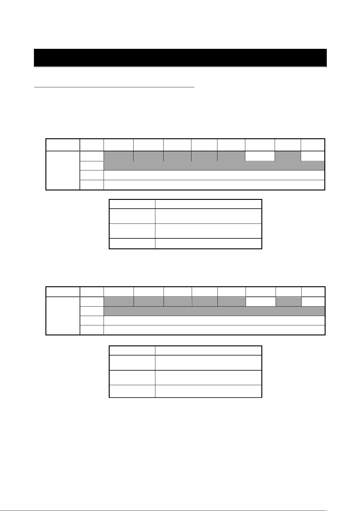
2. 1 EtherNet/IP Communication Function Connector/Terminal Specifications
Table 2.1 Communication function connector specifications (RJ-45 8 poles)
EIP66-Z connector CN3/4
Pin No.
Usage
Description
1
TX+
Transmission signal line (+)
2
TX-
Transmission signal line (-)
3
RX+
Reception signal line (+)
4
-
Unused
5
-
6
RX-
Reception signal line (-)
7
-
Unused
8
-
Table 2.2 Communication function terminal specifications
EIP66-Z terminal block
TB3
Terminal name
Usage
Description
FG
Safety ground terminal
Shielded terminal (M4) for CN3/CN4
2. 2 EtherNet/IP Communication Specifications
Table 2.3 EtherNet/IP communication specifications
Ethernet
Compliance standard
IEEE802.3i (10BASE-T)/IEEE802.3u (100BASE-TX)
Transmission speed
10/100 Mbps (automatic switching)
Communication mode
Full-duplex/half-duplex (automatic switching)
Connection type
Star/daisy chain connection
Interface
RJ-45 connector
Transmission distance
(between nodes or node and hub)
Within 100 m (depends on the specification of used cable)
Connected cable
Shielded twisted pair cable (STP): Category 5 or higher
Straight, cross (automatic switching)
EtherNet/IP
IP address setting
Set by the setting parameter of VF66 inverter main unit.
Communication function
Cyclic communication (Implicit message)
Message communication (Explicit message)
Vendor ID
178
Product Code
13
Device Type
AC Drive Profile
Product Name
EIP66 Series
ACD function (Address Conflict Detection)
Supported
Conformance test
EtherNet/IP CT-11
EDS file
EIP66 Series 1_0.eds

9
2. 3 Device Profile
An ODVA certified AC drive profile and Toyo original profile that works as a vendor-specific expanded
profile are available for EIP66-Z.
Standard profile
AC drive profile
Expanded profile
Toyo original profile
Select a profile to use using the inverter setting parameter. (Refer to Section 3.3.)
2. 4 Others
For the terminal block and other specifications, refer to "EIP66-Z Operating Instructions."
WARNING [Wiring]
Check that the input power is turned off before wiring.
Otherwise, electric shock/fire may result.
CAUTION [Wiring]
Never connect the G and G2 terminals to a ground.
Ignoring this may cause failure/damage.
Do not bring the PS and G terminals into contact or connect them.
Ignoring this may cause failure/damage.

10
CHAPTER 3 Communication Function Description
3. 1 Parameter Setting
The EIP66-Z EtherNet/IP communication function allows users to input a command related to operation, speed,
torque, etc. to the VF66 inverter or monitor the situations including the inverter operation/protection status,
current and voltage. In addition, reading/rewriting of inverter setting parameters and reading of traceback data,
protection history and monitoring data are available. This function can also be used as an input/output signal
of the internal PLC function of the VF66 inverter. For the internal PLC function, refer to the VF66 PC Tool manual.
To communicate with the EtherNet/IP scanner (master), the following VF66 inverter setting parameters need to
be set. Read also "EIP66-Z Operating Instructions" and operating instructions of VF66 inverter main unit and
scanner to use.
As for the direction of EtherNet/IP communication in this chapter, "Input" indicates the direction of input
from EIP66-Z to the network, and "Output" indicates the direction of output from the network to EIP66-Z. This
does not apply to the descriptions of the internal PLC function and multifunction input.
Table 3.1.1 EtherNet/IP communication related settings
Display
Item
Setting band (selection item)
Default
Driving
ReWrite
J-00
1: Digital communication option selection
0: Communication option not used
8: Use EIP66-Z
1 to 7: Set to use other options
0
x
J-07
IP address setting (high-order 2 bytes)
Set an IP address in hexadecimal
notation.
For the case of 192. 168. 100. 1,
0
x
J-08
IP address setting (low-order 2 bytes)
set J-07 to C0A8, and
J-08 to 6401.
0
x
J-09
Output Assembly
Instance number setting
0: Instance No. 20 (standard profile)
2: Instance No. 100 (expanded profile)
10: Instance No. 108 (expanded profile)
(refer to Section 3.3)
0
x
J-10
Input Assembly
Instance number setting
0: Instance No. 70 (standard profile)
14: Instance No. 132 (expanded profile)
15: Instance No. 140 (expanded profile)
(refer to Section 3.3)
0
x
J-11
SpeedScale setting
-126 to 127
3
x
J-12
MonitorDataNo. setting
0 to 119
3
○
J-16
Subnet mask setting (high-order 2 bytes)
Set a subnet mask in hexadecimal notation.
0
x
J-17
Subnet mask setting (low-order 2 bytes)
0
x
J-18
Default gateway setting (high-order 2 bytes)
Set a default gateway in hexadecimal
notation.
0
x
J-19
Default gateway setting (low-order 2 bytes)
0
x

11
* When a change is made in these settings, turn off the inverter power and then turn it on again.
・"J-11" is used to set the speed scaling coefficient (AC/DC Drive object attribute 22 "SpeedScale") used by
the standard profile (AC drive). This speed scaling coefficient determines the resolution of speed detection
value (SpeedActual) and speed setting value (SpeedRef).
Resolution = r/min/2SpeedScale
With the default value (= 3), the resolution becomes 0.125 r/min.
・"J-12" is used to set MonitorDataNo. used by the instance 140.
For more information about the setting value, refer to Section 4.2.4.
EIP66-Z allows the use of internal PLC function when the expanded profile is selected. Whether to use the internal
PLC function can be set using the VF66 inverter setting parameters (area i) as shown in the following table.
For more information, refer to the operating instructions of VF66 inverter main unit.
Table 3.1.2 Selecting use of internal PLC function
Display
Item
Selection item
Default
Driving
ReWrite
i-00
PLC-L function usage selection
off: Unused
on: Used
off
x
i-01
PLC-H function usage selection
0: Unused
1: Used
2: Used (PLCH output recognized as
speed command input)
0
x
・Use the internal PLC function when "J-09" and "J-10" are set to 2 or more (expanded profile).
・For the internal PLC function, refer to the VF66 PC Tool manual.
* In using the PLC-L function, each bit of the first and second words does not function as an operation control
or multifunction input signal. In this case, create a sequence to operate the operation control signal by
the internal PLC function.

12
3. 2 Speed Commanding Place Setting
To enable various commands on the VF66 inverter via communication, the following inverter setting parameters
need to be set appropriately. To enable the operation control signal of first word, turn on the forward operation
terminal "ST-F" on the terminal block TB1 of VF66 inverter control board VFC66-Z. For more information, refer
to the operating instructions of VF66 inverter main unit.
Table 3.2 Commanding place selection setting
Display
Item
Setting band (selection item)
Default
Driving
ReWrite
b-09
Commanding place when coupled
0: Terminal block
1: Console (SET66-Z)
2: Digital communication option
1
x
b-10
Speed commanding place
selection(*1)
0: Coupled
1: Analog input (1) (AIN1)
2: Console (SET66-Z)
3: Digital communication option
4: Analog input (2) (AIN2)
5: (For external extension option)
6: Analog input (3) (AIN3)
7: Internal PLC
0
x
b-11
Operation commanding place
selection
0: Coupled
1: Terminal block
2: Console (SET66-Z)
3: Digital communication option
0
x
b-12
JOG commanding place selection
0: Coupled
1: Terminal block
2: Console (SET66-Z)
3: Digital communication option
0
x
i-07
Operation mode selection(*2)
0: Speed control (ASR) mode
1: Torque command negative direction
prioritized
2: Torque command positive direction
prioritized
3: Torque control (ATR) mode
4: Speed/torque control setting change
0
x
i-08
Torque command input place
selection(*2)
1: Analog input (1) (AIN1)
1: Analog input (2) (AIN2)
2: Digital communication option
3: Internal PLC output
1
x
J-14
Date/time data selection from
communication
0: Without date/time data
1: With date/time data
0
x
(*1) This becomes "Frequency commanding place selection" when V/f mode is selected for the inverter mode.
(*2) This cannot be set when V/f mode is selected for the inverter mode.
・To control the inverter via a scanner (master) on the network using the standard profile (AC drive), set
the parameter "b-10" (Speed commanding place selection) to 3 (Digital communication option).
With "b-10" set to 3, EIP66-Z sets the speed commanding place (AC/DC Drive object attribute 4 "NetRef") to
network control at power-on to receive a speed command from a scanner on the network.
With "b-10" set to a value other than 3, EIP66-Z sets the speed commanding place to local control and ignores
a speed command from a scanner.

13
・To control the inverter via a scanner (master) on the network using the standard profile (AC drive), set
the parameter "b-11" (Operation commanding place selection) to 3 (Digital communication option).
With "b-11" set to 3, EIP66-Z sets the operation commanding place (Control Supervisor object attribute 5
"NetCtrl") to network control at power-on to receive an operation command from a scanner on the network.
With "b-11" set to a value other than 3, EIP66-Z sets the operation commanding place to local control and
ignores an operation command from a scanner.
3. 3 I/O Assembly Instance Number Setting
The EIP66-Z I/O Assembly instance number is set by the inverter setting parameters "J-09" (Output Assembly
instance number setting) and "J-10" (Input Assembly instance number setting). These values are set on
EIP66-Z at power-on. The default values are both 0.
Table 3.3
Parameter name
Device profile
Setting
value
Instance
number
Name
Size
(word)
"J-09"
Output Assembly
instance number
setting
Standard profile
(AC drive)
0
20
Basic Speed Control Output
2
Expanded profile
(Toyo original)
2
100
Special 1 Control Output
4
10
108
Special 9 Control Output
12
"J-10"
Input Assembly
instance number
setting
Standard profile
(AC drive)
0
70
Basic Speed Control Input
2
Expanded profile
(Toyo original)
14
132
Special 13 Control Input
18
15
140
Special 14 Control Input
4
・When the "J-09" instance number is set to 20, select 70 for the "J-10" instance number.
When the "J-09" instance number is set to a value other than 20, select a value other than 70 for the
"J-10" instance number.
The standard profile and expanded profile cannot be set together.
・Specifying 1 for "J-09" selects the instance number 20, and specifying any value from 3 to 9 selects
the instance number 108.
・Specifying 1 for "J-10" selects the instance number 70, and specifying any value from 2 to 13 selects
the instance number 132.
14
CHAPTER 4 I/O Assembly
4. 1 Standard I/O Assembly Data Attribute Format
The following shows the data format for the case of selecting the standard profile (AC drive profile).
4. 1. 1 Output Assembly Instance
Table 4.1.1
Instance
Byte
Bit 7
Bit 6
Bit 5
Bit 4
Bit 3
Bit 2
Bit 1
Bit 0
20
0
Fault Reset
Run Fwd
J-09 = 0
1
(2 words)
2
Speed Reference (low-order byte)
3
Speed Reference (high-order byte)
Name
Description
Run Fwd
Forward operation command
0: Stop, 1: Run
Fault Reset
Fault reset
0 -> 1 = Fault reset
Speed Reference
Speed setting value
4. 1. 2 Input Assembly Instance
Table 4.1.2
Instance
Byte
Bit 7
Bit 6
Bit 5
Bit 4
Bit 3
Bit 2
Bit 1
Bit 0
70
0
Running1
Faulted
J-10 = 0
1
(2 words)
2
Speed Actual (low-order byte)
3
Speed Actual (high-order byte)
Name
Description
Faulted
Abnormal
0: Normal, 1: Run
Running1
Running
0: Stop, 1: Running
Speed Actual
Speed detection value

15
4. 1. 3 SpeedRef/SpeedActual Calculation Method
The inverter provides the following three modes, and the calculation method of SpeedRef/SpeedAcutal
varies by the mode.
(1) Induction motor V/f mode
(2) Induction motor vector mode
(3) ED motor vector mode
SpeedRef/SpeedAcutal calculation method in the vector mode
In the vector mode (2 and 3), SpeedRef and SpeedAcutal are calculated using SpeedScale as follows.
SpeedRef (AC/DC Drive object attribute 8)
= Rotational speed command x 2SpeedScale
SpeedActual (AC/DC Drive object attribute 7)
= Motor speed x 2SpeedScale
SpeedRef calculation example in the vector mode
・SpeedRef = 4567
・SpeedScale = 3
Speed command = SpeedRef/2SpeedScale
= 570.875 r/min
SpeedRef/SpeedAcutal calculation method in the V/f mode
In the V/f mode (1), a motor pole number is required as well as SpeedScale to calculate SpeedRef
and SpeedAcutal.
The motor pole number is specified by the inverter setting parameter "A-06."
SpeedRef (AC/DC Drive object attribute 8)
= {(Frequency command x 60)/(Motor pole number/2)} x 2Speedscale
SpeedActual (AC/DC Drive object attribute 7)
= {(Rotational frequency x 60)/(Motor pole number/2)} x 2Speedscale
SpeedRef calculation example in the V/f mode
・Number of motor poles = 4 poles
・Frequency command = 30 Hz
・SpeedScale = 3
SpeedRef = {(30 Hz x 60)/(4 poles/2)} x 23
= 7200
16
4. 2 Expanded I/O Assembly Data Attribute Format
The following shows the data format for the case of selecting the expanded profile (Toyo original
profile).
4. 2. 1 Output Assembly Instance
Table 4.2.1
Instance
Byte
Bit 7
Bit 6
Bit 5
Bit 4
Bit 3
Bit 2
Bit 1
Bit 0
100
J-09 = 2
(4 words)
0
Preset2
Preset1
Protection
status reset
Fault Reset2
DC brake command
DC-Brake
Initial
excitation
command
Excit.
Reverse
operation
command
Rev
JOG command
Jog
Operation
command
Start
[I00027]
[I00026]
[I00025]
[I00024]
[I00023]
[I00022]
[I00021]
[I00020]
1
Max-SPD
Reduce
S-ARC off
Speed hold
Spd Hold
MRH deceleration
MRH down
MRH
acceleration
MRH up
Acc/DecSel2
Acc/DecSel1
Preset3
[I0002F]
[I0002E]
[I0002D]
[I0002C]
[I0002B]
[I0002A]
[I00029]
[I00028]
2
Ex-Fail.1
(no 86A)
External failure
4
Ex-Fail.4
External failure
3
Ex-Fail.3
External failure
2
Ex-Fail.2
External
failure 1
Ex-Fail.1
Rev Cmd
ATRMode
Droop control
OFF
Droop off
[I00037]
[I00036]
[I00035]
[I00034]
[I00033]
[I00032]
[I00031]
[I00030]
3
SPD.Ref.
Term
Unused
Emergency stop
(Normally open)
input
EMG.Stop
Second Motor
Trace Trg.
Ex-Fail.4
(no 86A)
Ex-Fail.3
(no 86A)
Ex-Fail.2
(no 86A)
[I0003F]
[I0003E]
[I0003D]
[I0003C]
[I0003B]
[I0003A]
[I00039]
[I00038]
4
Communication speed command: Speed Reference2
(20000/top)
(Low-order byte)
Communication input register 1 [i00010]
(Low-order byte)
5
Communication speed command: Speed Reference2
(20000/top)
(High-order byte)
Communication input register 1 [i00010]
(High-order byte)
6
Communication torque command: Torque Reference
(5000/100 %)
(Low-order byte)
Communication input register 2 [i00011]
(Low-order byte)
7
Communication torque command: Torque Reference
(5000/100 %)
(High-order byte)
Communication input register 2 [i00011]
(High-order byte)
108
J-09 = 10
(12 words)
8
Date
(Low-order byte)
Communication input register 3 [i00012]
(Low-order byte)
9
Month
(High-order byte)
Communication input register 3 [i00012]
(High-order byte)
10
Minute
(Low-order byte)
Communication input register 4 [i00013]
(Low-order byte)
11
Hour
(High-order byte)
Communication input register 4 [i00013]
(High-order byte)
12
(Not specified)
Communication input register 5 [i00014]
(Low-order byte)
13
(Not specified)
Communication input register 5 [i00014]
(High-order byte)
14
(Not specified)
Communication input register 6 [i00015]
(Low-order byte)
15
(Not specified)
Communication input register 6 [i00015]
(High-order byte)
16
(Not specified)
Communication input register 7 [i00016]
(Low-order byte)
17
(Not specified)
Communication input register 7 [i00016]
(High-order byte)
18
(Not specified)
Communication input register 8 [i00017]
(Low-order byte)
19
(Not specified)

17
Communication input register 8 [i00017]
(High-order byte)
20
(Not specified)
Communication input register 9 [i00018]
(Low-order byte)
21
(Not specified)
Communication input register 9 [i00018]
(High-order byte)
22
(Not specified)
Communication input register 10 [i00019]
(Low-order byte)
23
(Not specified)
Communication input register 10 [i00019]
(High-order byte)
・When the instance 100 (J-09 = 2) is used, the Output Assembly data length becomes four words.
・When the instance 108 (J-09 = 10) is used, the Output Assembly data length is 12 words.
When the internal PLC function is not used, the seventh word and the followings will be ignored.
・When the internal PLC function is used, each bit of the first and second words of Output Assembly data
becomes an input relay of the internal PLC function. The third word and the followings become input
registers of the internal PLC function.
For the allocation of Output Assembly data to the input relay/register of the internal PLC function,
see Table 4.2.1.

18
4. 2. 2 Input Assembly Instance
Table 4.2.2
Instance
Byte
Bit 7
Bit 6
Bit 5
Bit 4
Bit 3
Bit 2
Bit 1
Bit 0
132
J-10 = 14
(18 words)
0
Gate driving
Auto measurement
(auto tuning)
in operation
Power failure
DC excitation
Reverse
operation
command
JOG operation
Inverter running
(deceleration
stop included)
Operation/JOG
command input
1
External signal
input 4
External signal
input 3
External signal
input 2
External signal
input 1
Second setting
block selected
External DB
protection
operation or
communication
abnormality
DC brake
Initial
excitation
2
Current sensor
abnormality
Overload
protection
DC part
overvoltage
Gate board
abnormality
Unused
(unspecified)
Unused
(unspecified)
IGBT protection
operation
Overcurrent
protection
3
Optional error
Memory
abnormality
Unit overheat
Overtorque
protection
Insufficient
voltage (power
failure)
Overfrequency
protection
Overspeed
protection
Start delay
4
Open phase
Setting error
FCL operation
Charging
resistance
overheat
Motor overheat
Speed control
error
Communication
timeout error
Sensorless
start error
5
External failure
4
External failure
3
External failure
2
External failure
1
Sensor error
PG error
Fan failure
CPU abnormal
process
6
Setting reached
Speed detection 2
(spd <= detect2)
Speed detection 2
(spd >= detect2)
Speed detection 2
(spd = detect2)
Speed detection
1 (spd <=
detect1)
Speed detection
1 (spd >=
detect1)
Speed detection 1
(spd = detect1)
Unused
(unspecified)
[O00047]
[O00046]
[O00045]
[O00044]
[O00043]
[O00042]
[O00041]
[O00040]
7
Cooling fan
failure
Second setting
block
selected
Reverse
operation
Retry by failure
Overload
pre-alarm
Power failure
detected
Absolute torque
value detection
Torque
detection
[O0004F]
[O0004E]
[O0004D]
[O0004C]
[O0004B]
[O0004A]
[O00049]
[O00048]
8
Motor speed: Speed Actual2 (20000/top)
(Low-order byte)
Communication output register 1 [o00010]
(Low-order byte)
9
Motor speed: Speed Actual2 (20000/top)
(High-order byte)
Communication output register 1 [o00010]
(High-order byte)
10
ARC output: ARC out (20000/top)
(Low-order byte)
Communication output register 2 [o00011]
(Low-order byte)
11
ARC output: ARC out (20000/top)
(High-order byte)
Communication output register 2 [o00011]
(High-order byte)
12
Effective current: RMS Motor Current (10000/100 % [Inv.rated])
(Low-order byte)
Communication output register 3 [o00012]
(Low-order byte)
13
Effective current: RMS Motor Current (10000/100 % [Inv.rated])
(High-order byte)
Communication output register 3 [o00012]
(High-order byte)
14
Torque Command (5000/100 %)
(Low-order byte)
Communication output register 4 [o00013]
(Low-order byte)
15
Torque Command (5000/100 %)
(High-order byte)
Communication output register 4 [o00013]
(High-order byte)
16
DC Voltage (10/1 V [200 V class], 5/1 V [400 V class])
(Low-order byte)
Communication output register 5 [o00014]
(Low-order byte)
17
DC Voltage (10/1 V [200 V class], 5/1 V [400 V class])
(High-order byte)
Communication output register 5 [o00014]
(High-order byte)
18
Output Voltage (20/1 V [200 V class], 10/1 V [400 V class])
(Low-order byte)
Communication output register 6 [o00015]
(Low-order byte)
19
Output Voltage (20/1 V [200 V class], 10/1 V [400 V class])
(High-order byte)
Communication output register 6 [o00015]
(High-order byte)
20
Output Frequency (20000/top)
(Low-order byte)
Communication output register 7 [o00016]
(Low-order byte)
21
Output Frequency (20000/top)
(High-order byte)
Communication output register 7 [o00016]
(High-order byte)
22
OL Pre-counter (10000/100 %)
(Low-order byte)
Communication output register 8 [o00017]
(Low-order byte)
23
OL Pre-counter (10000/100 %)
(High-order byte)
Communication output register 8 [o00017]
(High-order byte)
19
24
Motor Temperature (10/1 ℃)
(Low-order byte)
Communication output register 9 [o00018]
(Low-order byte)
25
Motor Temperature (10/1 ℃)
(High-order byte)
Communication output register 9 [o00018]
(High-order byte)
26
Motor Flux (1024/100 %)
(Low-order byte)
Communication output register 10 [o00019]
(Low-order byte)
27
Motor Flux (1024/100 %)
(High-order byte)
Communication output register 10 [o00019]
(High-order byte)
28
(Not specified)
Communication output register 11 [o0001A]
(Low-order byte)
29
(Not specified)
Communication output register 11 [o0001A]
(High-order byte)
30
(Not specified)
Communication output register 12 [o0001B]
(Low-order byte)
31
(Not specified)
Communication output register 12 [o0001B]
(High-order byte)
32
(Not specified)
Communication output register 13 [o0001C]
(Low-order byte)
33
(Not specified)
Communication output register 13 [o0001C]
(High-order byte)
34
(Not specified)
Communication output register 14 [o0001D]
(Low-order byte)
35
(Not specified)
Communication output register 14 [o0001D]
(High-order byte)
140
J-10 = 15
(4 words)
0
Gate driving
Auto measurement
(auto tuning)
in operation
Power failure
DC excitation
Reverse
operation
command
JOG operation
Inverter running
(deceleration
stop included)
Operation/JOG
command input
1
Failure code: ProtectErrorCode (See Table 4.2.3)
DC brake
Initial
excitation
2
Monitor Number 1 Data (low-order byte) (See Table 4.2.4)
3
Monitor Number 1 Data (high-order byte) (See Table 4.2.4)
4
Monitor Number 2 Data (high-order byte) (See Table 4.2.4)
5
Monitor Number 2 Data (low-order byte) (See Table 4.2.4)
6
Monitor Number 3 Data (high-order byte) (See Table 4.2.4)
7
Monitor Number 3 Data (low-order byte) (See Table 4.2.4)
・When the instance 132 (J-10 = 14) is used, the Input Assembly data length is 18 words.
When the internal PLC function is not used, the 15th word and the followings will be unspecified.
・When the instance 140 (J-10 = 15) is used, the Input Assembly data length is four words.
・When the internal PLC function is used, each bit of the fourth word of Input Assembly data becomes
an output relay of the internal PLC function. The fifth word and the followings become output registers
of the internal PLC function.
For the allocation of Input Assembly data to the output relay/register of the internal PLC function,
see Table 4.2.2.

20
4. 2. 3 Failure Code
The following shows failure codes of the Input Assembly instance 140 (ProtectErrorCode). If multiple
failures/protection operations occur at the same time, a smaller number is used.
Table 4.2.3
Code
Failure/protection item
Code
Failure/protection item
0
No failure/protection
17
Sensorless start error
1
Overcurrent protection
18
Communication timeout error
2
IGBT protection operation
19
Speed control error
3
20
Motor overheat
4
21
Charging resistance overheat
5
GAC abnormality
22
FCL operation
6
DC part overvoltage
23
Setting error
7
Overload protection
24
Open phase
8
DCCT abnormality
25
CPU abnormal process
9
Start delay
26
FAN failure
10
Overspeed protection
27
PG error
11
Overfrequency protection
28
Sensor abnormality
12
Insufficient voltage (power
failure)
29
External failure 1
13
Overtorque protection
30
External failure 2
14
Unit overheat
31
External failure 3
15
Memory abnormality
32
External failure 4
16
Optional error
Other manuals for VF66
1
Table of contents
Other TOYODenki Inverter manuals


