TOYODenki VF66 EIP66-Z User manual

TOYO INTELLIGENT INVERTER
EIP66-Z Operating Manual


3
Preface
Thank you very much for choosing our inverter optional board.
This manual describes handling of the optional board EIP66-Z designed for VF66 inverter. Please read this manual
thoroughly to use EIP66-Z properly.
This manual describes the terminal block functions of EIP66-Z board, wiring, switch settings and VF66 inverter
settings. For the EtherNet/IP communication functions, refer to "EIP66-Z Communication Protocol Manual."
To use various functions according to intended use as well as the inverter functions, read the operating
instructions of VF66 inverter main unit or dedicated manual thoroughly before use.

4
Be Sure To Read This Before Use
Safety Notice
To use the EIP66-Z correctly, be sure to completely read this manual and all other attached documents before
installation, operation, maintenance, and inspection. You need to have a good knowledge of equipment, safety
information, and all notices before using the EIP66-Z. Read also the operating instructions of VF66 inverter
main unit and other related manuals thoroughly before use for safe operations.
In this manual, safety notices are ranked as "Danger," "Warning," and "Caution."
WARNING
When improper use may cause a dangerous situation, and death or serious
injury may result.
CAUTION
When improper use may cause a dangerous situation, medium-level or minor
injury may result, and only physical damage may result. However, it can
cause serious results depending on the situation. Cautions described in
this manual are all important. Be sure to observe them.
CAUTION [Installation]
⚫Do not use the product if it is found damaged or deformed in unpacking.
It may cause failure/malfunction.
⚫Do not put a flammable material near the product.
It may catch fire.
⚫Do not give a shock to the product by dropping or toppling it.
It may cause failure/damage to the product.
⚫Do not install an optional board with damage or missing part to perform operations.
It may cause injury.
WARNING [Wiring]
⚫Check that the input power is turned off before wiring.
Otherwise, electric shock/fire may result.
⚫After turning off the power, wait at least ten minutes before opening the inverter front cover.
⚫Be sure to connect a ground wire.
Otherwise, electric shock/fire may result.
⚫Let an electrical engineering technician do the wiring work.
Otherwise, electric shock/fire may result.
⚫Be sure to install the main unit before wiring.
Otherwise, electric shock/fire may result.

5
CAUTION [Wiring]
⚫Be sure to attach and lock the communication cable and connector.
Otherwise, failure/malfunction may result.
WARNING [Operation]
⚫Be sure to attach the inverter front cover before turning on the input power.
Do not remove the cover while the inverter is energized.
Ignoring this may cause electric shock.
⚫Do not operate the switches with wet hands.
Ignoring this may cause electric shock.
⚫While the inverter is energized, do not touch the inverter terminals even when the inverter is stopped.
Ignoring this may cause electric shock.
⚫Resetting an alarm with the operation signal input causes a sudden restart.
Perform resetting after making sure that the operation signal is off.
Otherwise, you may be injured.
⚫The inverter operation setting is available from low to high speed. Check the allowable range of motor
or machine carefully before starting operation.
Otherwise, injury/failure/damage may result.
CAUTION [Operation]
⚫Do not touch the inverter radiation fin or discharge resistor because it can be very hot.
Ignoring this may cause burn injury.
WARNING [Maintenance/inspection and part replacement]
⚫Be sure to turn off the power before performing inspection.
Otherwise, electric shock/injury/fire may result.
⚫Only the specified person must perform maintenance/inspection and part replacement.
Use an insulated tool for maintenance/inspection.
Otherwise, electric shock/injury may result.
CAUTION [Others]
⚫Never modify the product.
Otherwise, electric shock/injury may result.
CAUTION [General cautions]
Some figures in this manual are shown with the cover or safety shield removed for the purpose of detailed
descriptions. However, for actual operations, be sure to attach the specified cover or safety shield and follow
the instructions in this manual.
Note that these safety precautions and specifications described in each manual are subject to change without
notice.

6
Contents
Be Sure To Read This Before Use .................................................................................................................................... 4
Safety Notice............................................................................................................................................................... 4
CHAPTER 1 Function Overview............................................................................................................................................ 7
CHAPTER 2 Basic Specifications ...................................................................................................................................... 8
2. 1 Multifunction Input Terminal Specifications .......................................................................................... 8
2. 2 Analog Input/Output Terminal Specifications .......................................................................................... 9
2. 3 PG Input/Output Terminal Specifications .................................................................................................. 9
2. 4 EtherNet/IP Communication Function Connector/Terminal Specifications........................................ 10
2. 5 EtherNet/IP Communication Specifications .............................................................................................. 10
2. 6 Others ................................................................................................................................................................ 11
CHAPTER 3 Board Description.......................................................................................................................................... 12
3. 1 Part Names......................................................................................................................................................... 12
3. 2 EIP66-Z Switches............................................................................................................................................. 13
3. 3 How to Mount..................................................................................................................................................... 14
3. 4 LED ...................................................................................................................................................................... 16
CHAPTER 4 Multifunction Input...................................................................................................................................... 18
4. 1 Multifunction Input....................................................................................................................................... 18
CHAPTER 5 Analog Input/Output Function .................................................................................................................... 21
5. 1 Analog Input (2)............................................................................................................................................. 21
5. 2 Analog Input (2) Gain/Offset Adjustment ................................................................................................ 22
5. 3 How to Use Analog Input (2)........................................................................................................................ 24
5. 4 Analog Output (2)........................................................................................................................................... 27
5. 5 Analog Output (2) Gain/Offset Adjustment .............................................................................................. 28
CHAPTER 6 PG Input/Output Function ............................................................................................................................ 31
6. 1 PG Input Signal............................................................................................................................................... 31
6. 2 PG Output Signal............................................................................................................................................. 33
CHAPTER 7 EtherNet/IP Communication Function......................................................................................................... 34
7. 1 EtherNet/IP Connection .................................................................................................................................34
7. 2 EtherNet/IP Communication Function Setting .......................................................................................... 35

7
CHAPTER 1 Function Overview
EIP66-Z is attached to the connector of the board (VFC66-Z) inside the VF66 inverter to use. EIP66-Z is equipped
with the EtherNet/IP adapter function (slave station), analog input/output function, multifunction input and
PG input/output function.
EtherNet/IP is a public network standard, and the specification and protocol are made public by ODVA (Open
DeviceNet Vendor Association, Inc.) to provide mutual compatibility between the devices of the same type by
multiple vendors.
The EIP66-Z EtherNet/IP communication function allows users to input a command related to operation, speed,
torque, etc. to the VF66 inverter or monitor the situations including the inverter operation/protection status,
current and voltage. In addition, reading/rewriting of inverter settings and reading of traceback data, protection
history and monitoring data are available. For the EtherNet/IP communication functions, refer to "EIP66-Z
Communication Protocol Manual." This function can also be used as an input/output signal of the internal PLC
function of the VF66 inverter. For the internal PLC function, refer to the VF66 PC Tool manual.
CAUTION [Safety precautions]
Read this manual thoroughly before use for proper handling.
Our inverter is not designed/manufactured for the devices or systems used in a life-threatening
situation.
Do not use this inverter for special use, such as riding mobile object, medical care, aerospace,
nuclear power control, submarine repeater/system, etc.
This inverter is manufactured under stringent quality control; however, install safety equipment
to avoid a serious accident for the important facility which may put human lives in danger by failure
of the inverter
or the facility to which a serious loss is caused by failure of the inverter.
Contact us to use this product for the load other than three-phase AC motors.
Electrical work is required for this inverter. Let an electrical engineering technician do the work.

8
CHAPTER 2 Basic Specifications
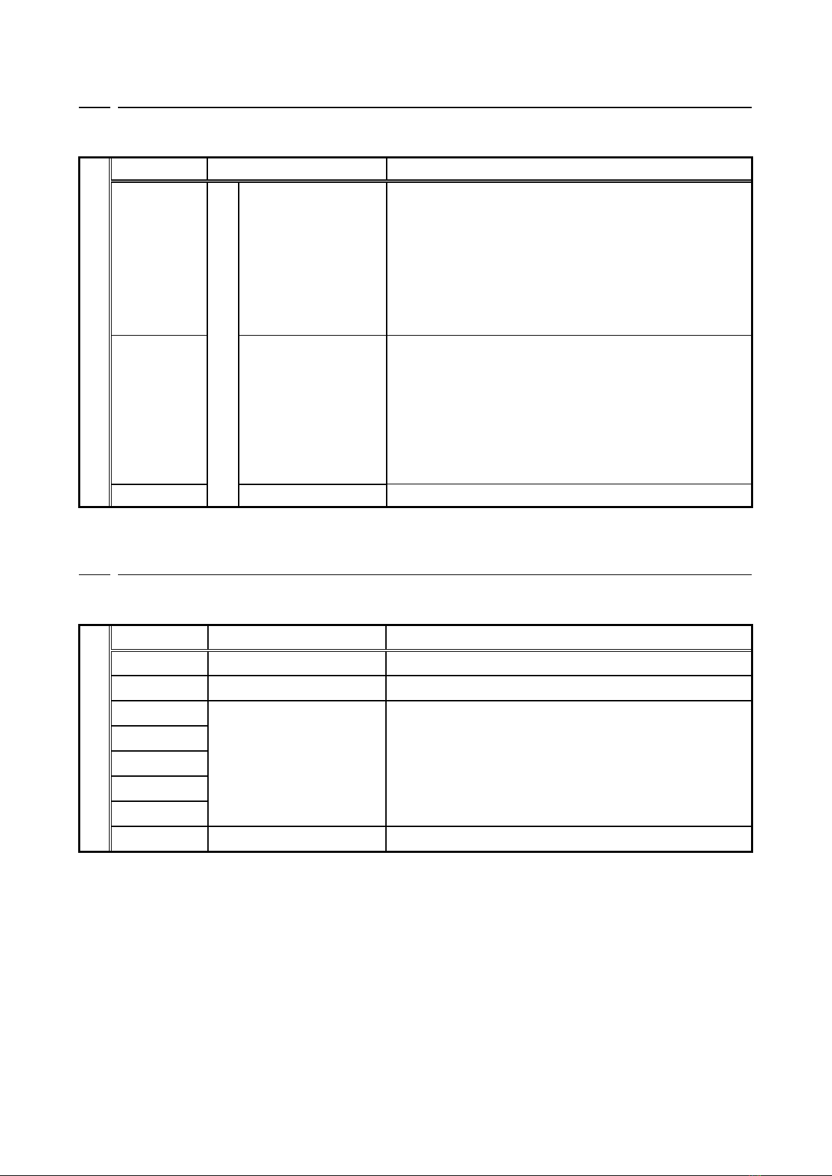
2. 1 Multifunction Input Terminal Specifications
Multifunction input
EIP66-Z terminal block TB1
Terminal name
Usage
Description
PS (2 terminals)
Multifunction input
+12 V power supply terminal
Outputs a direct voltage of +12 V.
G (2 terminals)
GND terminal
Do not connect G terminal to the ground terminal.
Do not bring PS and G terminals into contact or connect them.
MI6
Multifunction input terminal (6)
(Maximum input voltage 24 VDC/maximum input current 3 mA)
The same operation as VF66 inverter console is enabled
by inputting a signal to the multifunction input terminal.
[Under the default condition, the followings are set by the VF66 inverter
setting parameter: Area c.]
・Preset speed selection 1 is set for the multifunction input terminal (6).
・Preset speed selection 2 is set for the multifunction input terminal (7).
・Preset speed selection 3 is set for the multifunction input terminal (8).
・Acceleration or deceleration time selection 1 is set for the multifunction
input terminal (9).
* For more information about multifunction input terminals,
refer to the operating instructions of VF66 inverter main unit.
MI7
Multifunction input terminal (7)
MI8
Multifunction input terminal (8)
MI9
Multifunction input terminal (9)
Multifunction input source/sink mode setting jumper connector
EIP66-Z jumper connector
Connector
symbol
Usage
Description
CN-SO
Source mode
・Change the connection of jumper socket to jumper connector to switch
between the source and sink modes.
・Be sure to turn off the inverter power before changing the connection of
jumper socket.
[The source mode is selected in the default condition.]
・For the source mode, install a switch, etc. between the multifunction input
terminals (6) to (9) and PS terminal to turn ON/OFF.
・For the sink mode, install a switch, etc. between the multifunction input
terminals (6) to (9) and G terminal
to turn ON/OFF.
For more information, refer to CHAPTER 4.
CN-SI
Sink mode
9
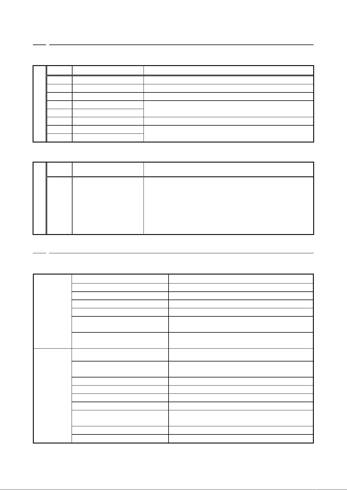
2. 2 Analog Input/Output Terminal Specifications
Analog input/output function
EIP66-Z terminal block TB1
Terminal name
Usage
Description
AIN2
Analog input/output
Analog input (2) terminal
・For the analog input (2) terminal, the input range can be selected
from 0 to ±10 V, 0 to 10 V, and 4 to 20 mA by switching of SW1
and changing of VF66 inverter setting parameter.
(For switching of the input range, refer to CHAPTER 5.)
・The input impedance at analog voltage input is 150 kΩ.
・The input resistance at analog current input is 250 Ω.
[The 0 to 10 V input is selected in the default condition.]
* For more information about the analog input (2) terminal,
refer to the operating instructions of VF66 inverter main unit.
AOT2
Analog output (2) terminal
・For the analog output (2) terminal, the output range can be selected
from 0 to 10 V and 0 to ±10 V (maximum current: 1 mA) by changing of
VF66 inverter setting parameter.
[The setting is made so that the inverter output current becomes 5
V/inverter rated current in the default condition.]
* For more information about the analog output (2) terminal,
refer to the operating instructions of VF66 inverter main unit.
G2
GND terminal
Do not connect G2 terminal to the ground terminal.
2. 3 PG Input/Output Terminal Specifications
PG input/output function
EIP66-Z terminal block TB2
Terminal name
Usage
Description
+12
+12 V power supply terminal
Outputs a direct voltage of +12 V.
G (3 terminals)
GND terminal
Do not connect G terminal to the ground terminal.
A
PG input terminal
Inputs A, B, U/Z, V or W signal
of 12 V power supply PG (complementary output).
B
U/Z
V
W
PGOUT
PG output terminal
Outputs a waveform of frequency divided A signal of PG.
10
2. 4 EtherNet/IP Communication Function Connector/Terminal Specifications
Communication function connector specifications (RJ-45 8 poles)
EIP66-Z connector CN3/4
Pin No.
Usage
Description
1
TX+
Transmission signal line (+)
2
TX-
Transmission signal line (-)
3
RX+
Reception signal line (+)
4
-
Unused
5
-
6
RX-
Reception signal line (-)
7
-
Unused
8
-
Communication function terminal specifications
EIP66-Z terminal block TB3
Terminal
name
Usage
Description
FG
Safety ground terminal
FG terminal (M4) for CN3/CN4
2. 5 EtherNet/IP Communication Specifications
EtherNet/IP communication specifications
Ethernet
Compliance standard
IEEE802.3i (10BASE-T)/IEEE802.3u (100BASE-TX)
Transmission speed
10/100 Mbps (automatic switching)
Communication mode
Full-duplex/half-duplex (automatic switching)
Connection type
Star/daisy chain connection
Interface
RJ-45 connector
Transmission distance
(between nodes or node and hub)
Within 100 m (depends on the specification of used cable)
Connected cable
Shielded twisted pair cable (STP): Category 5 or higher
Straight, cross (automatic switching)
EtherNet/IP
IP address setting
Set by the setting parameter of VF66 inverter main unit.
Communication function
Cyclic communication (Implicit message)
Message communication (Explicit message)
Vendor ID
178
Product Code
13
Device Type
AC Drive Profile
Product Name
EIP66 Series
ACD function (Address Conflict
Detection)
Supported
Conformance test
EtherNet/IP CT-11
EDS file
EIP66 Series 1_0.eds

11
2. 6 Others
Other standard specifications conform to the VF66 inverter. For more information, refer to the operating
instructions of VF66 inverter main unit.
WARNING [Wiring]
⚫Check that the input power is turned off before wiring.
Otherwise, electric shock/fire may result.
⚫Be sure to turn off the inverter power before changing the connection of jumper socket.
Otherwise, electric shock/injury/failure/malfunction may result.
CAUTION [Wiring]
⚫Never connect the G and G2 terminals to a ground.
Ignoring this may cause failure/damage.
⚫Do not bring the PS and G terminals into contact or connect them.
Ignoring this may cause failure/damage.
12
CHAPTER 3 Board Description
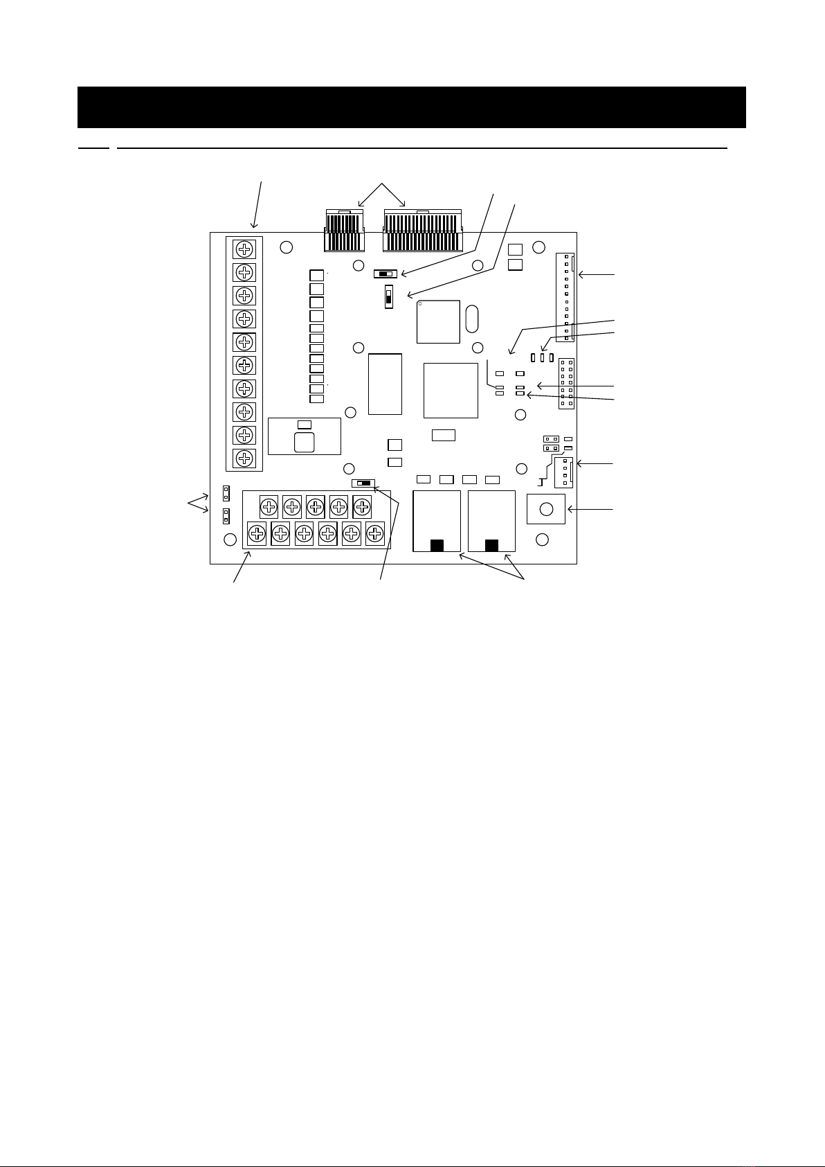
3. 1 Part Names
PS PS MI8 G AIN2 AOT2
MI6 MI7 MI9 G G2
CN-SI CN-SO
EIP66-Z
TB1
TB2 SW1
SW3
SW2
CN1 CN2
+12
A
B
G
G
U/Z
V
W
G
PG
OUT
CN5
CN3
Port0
CN4
Port1
LINK0 LINK1
TxRx0 TxRx1
LED1 LED2
LED5 LED6
MS NS
LED4
LED3
LED7
LED8
LED9
LED10 RDY
LED11 RUN
CN7
JP3
JP4
TB3
FG
①
②③
④
⑤
⑦
⑥
⑧
⑨⑩
⑪
⑫
⑭
⑬
⑮
⑯
Figure 3. 1 EIP66-Z board
①VFC66-Z connector (CN1, CN2)
②PG frequency division output switch (SW2)
③PG signal ON/OFF switch (SW3)
④External extension option (for future extension) connector (CN5)
⑤Analog input/output, multifunction input (TB1)
⑥Analog input signal characteristics changeover switch (SW1)
⑦Jumper connector for switching multifunction input signal characteristics (CN-SI, CN-SO)
⑧PG input/output terminal block (TB2)
⑨EtherNet/IP module status (MS) LED (LED5 green/red)
⑩EtherNet/IP network status (NS) LED (LED6 green/red)
⑪EtherNet/IP link (LINK) LED (LED3, LED4 green)
⑫EtherNet/IP transmission and reception (TxRx) LED (LED1, LED2 yellow)
⑬EtherNet/IP communication RJ-45 connector (CN3, CN4)
⑭Status LED (LED7, LED8, LED9)
⑮Maintenance connector, jumper connector, LED (CN7, JP3, JP4, LED10, LED11)
⑯FG terminal block (TB3)
For the connector connected to (4), use a Molex housing: 5051-12 and gold-plated terminal: 2759G or 2759PBG.
For the connection and use of CN5, refer to the operating instructions of IOEXT66-Z.
13
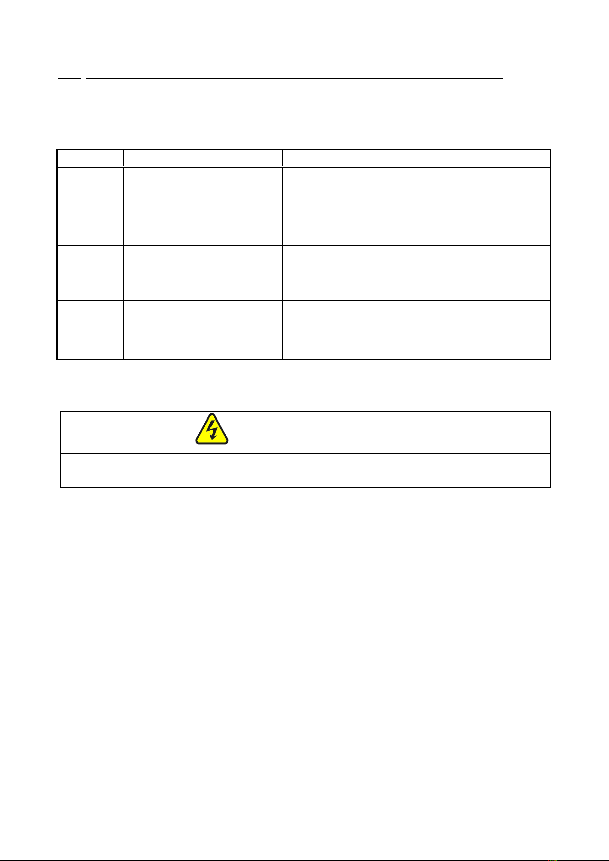
3. 2 EIP66-Z Switches
Various EIP66-Z functions can be changed using switches.
EIP66-Z switch functions
Switch name
Usage
Description
SW1
Analog input (2) signal characteristics
changeover switch
Changes the input signal characteristics of analog input (2) terminal.
・0 to 10 V or 0 to ±10 V input is available with the switch OFF.
・4 to 20 mA input is available with the switch ON.
[The switch is set to OFF in the default condition.]
* To change the input range, change the setting parameter of VF66 inverter
as well. For more information, refer to CHAPTER 5.
SW2
PG frequency division output switch
Changes the output waveform of frequency divided PG signal.
・1/4 frequency divided signal is output with the switch at 3 side.
・1/2 frequency divided signal is output with the switch at 1 side.
[The switch is set to 3 side in the default condition.]
SW3
PG signal ON/OFF switch
Turns on/off the PG signal.
・Disables PG signal input with the switch OFF.
・Enables PG signal input with the switch ON.
[The switch is set to ON in the default condition.]
WARNING [Switches]
⚫Be sure to turn off the inverter power before turning the switch.
Otherwise, electric shock/injury/failure/malfunction may result.

14
3. 3 How to Mount
Support
Optional board
Connector
SET66-Z
board
VFC66-Z
board
Figure 3. 2 Optional board mounting position (VF66B-2R222)
* For opening/closing of the inverter front cover, refer to the operating instructions of inverter main unit.
(1) Before starting to work, check that the inverter power is turned off.
(2) Mount the EIP66-Z board to the area enclosed by the dotted line in Figure 3.2 (the figure shows the case
of VF66B-2R222, but the same applies to the models with other capacities). If another optional board has
already been mounted, remove it according to the following procedure. If another optional board is not
mounted, proceed to (6).
(3) First, remove the SET66-Z board to remove an optional
board safely. Remove the four screws encircled in the
right figure and pull out the SET66-Z board from the
VFC66-Z board.
(4) Next, release the two connectors between the VFC66-Z
board and optional board. Figure 3. 4 (a) shows the state
with the connector fixed. As shown in Figure 3.4 (b), push
up the tab to release the connector.
(5) The supports that fix the optional board to the inverter
chassis are located in the four areas encircled in Figure
3.2. Push the pawl part shown in Figure 3.5 into the
Screw
Figure 3. 3 SET66-Z board
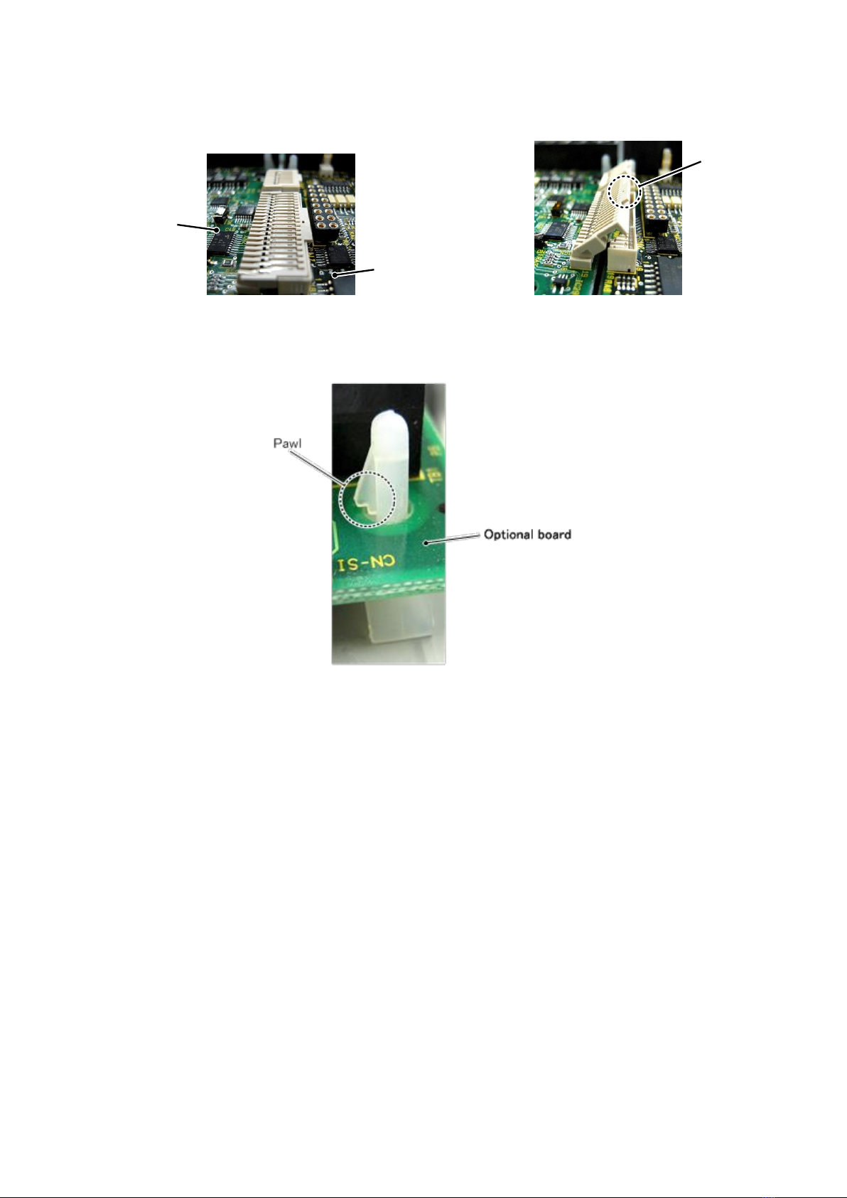
15
support and remove the optional board.
Tab
Optional board
VFC66-Z
board
(a) Fixed connector (b) Connector tab
Figure 3. 4 Connector
Figure 3. 5 Pawl part of support
(6) Align the four holes on the EIP66-Z board with the support positions encircled in Figure 3.2, and push
the board until the pawl part of the support is hooked to the top of the board as shown in Figure 3.5.
(7) Fit the EIP66-Z board connectors CN1 and CN2 into the VFC66-Z board connectors CN7 and CN4, respectively,
by pushing down the tab as shown in Figure 3.4 (b). Figure 3.4 (a) shows the state with the connector
fixed. The moving part of the connector is elastic. Fix it securely to prevent disconnection.
(8) Reattach the SET66-Z board.
(9) Reattach the inverter front cover.
16
WARNING [Attachment/removal]
⚫Be sure to turn off the inverter power before attaching or removing a board.
Otherwise, electric shock/injury/failure/malfunction may result.
CAUTION [Attachment/removal]
⚫Do not attach/remove the connector repeatedly.
Loosened connection part of the connector may cause problems such as connection failure.
⚫Do not insert the objects other than the proper fitted object.
Deformed connection part of the connector may cause problems such as connection failure.
3. 4 LED
・LED1 (TxRx0) and LED2 (TxRx1) operation
Blinks when the EtherNet/IP communication is performed or data is transmitted/received.
LED1 and LED2 support Port0 (CN3) and Port1 (CN4), respectively.
・LED3 (LINK0) and LED4 (LINK1) operation
Lights up when a link is established in the network.
LED3 and LED4 support Port0 (CN3) and Port1 (CN4), respectively.
・LED5 (MS) operation
The module status LED lights up in two colors (green/red) to indicate the device status.
It indicates whether the device is powered on and the device functions normally.
The following table defines the status of module status LED.
Status
LED
Description
Power Off
Off
Power is not supplied to the device.
Device Operational
Green
The device functions normally.
Standby
Blinking green
The device has not been set.
Minot Fault
Blinking red
A recoverable error occurs in the device.
Major Fault
Red
An unrecoverable error occurs in the device.
Device replacement may be necessary.
Self-Test
Blinking red and green
The device is undergoing self-diagnostic test at power-on.

17
・LED6 (NS) operation
The network status LED lights up in two colors (green/red) to indicate the communication link status.
The following table shows the status of network status LED.
Status
LED
Description
Not powered, no IP
address
Off
No IP address exists in the device. Or power is not supplied to the
device.
No connections
Blinking green
Connection is not established, but IP address is obtained.
Connected
Green
Connection is established.
Connection Timeout
Blinking red
Connection time-out occurs.
Duplicate IP
Red
IP address overlaps with another device.
Self-Test
Blinking red and green
The device is undergoing self-diagnostic test at power-on.
・LED7 (CPURUN) operation
While EIP66-Z functions normally, LED7 blinks at intervals of approx. one second. If LED7 does not blink normally
after power-on,
the following causes are suspected.
➢Poor contact between VFC66-Z and EIP66-Z
➢Failure of VFC66-Z or EIP66-Z
・LED8 (COMM) operation
LED8 lights up while the connection for cyclic communication is established.
When the standard profile is used, it lights up also when the connection for message communication is
established.
・LED9 (ALRM) operation
LED9 lights up or blinks when a setting error of device occurs. If LED9 lights up or blinks at power-on,
the following causes are suspected.
➢Instance number setting error (lights up)
➢IP address setting error (blinks)
➢Conflict of IP addresses detected at start-up (blinks)
➢EtherNet/IP communication IC failure (lights up or blinks)
CAUTION [Safety precautions]
⚫If LED7 does not function normally, it may indicate a failure of EIP66-Z or VFC66-Z.

18
CHAPTER 4 Multifunction Input
4. 1 Multifunction Input
EIP66-Z
TB1
PS
4.7kΩ
MI7
MI6
4.7kΩ
MI8
4.7kΩ
MI9
4.7kΩ
G
Internal
power
supply
(12V)
CN-SO
CN-SI
Multi function
input 6
Multi function
input 7
Multi function
input 8
Multi function
input 9
EIP66-Z
TB1
PS
4.7kΩ
MI7
MI6
4.7kΩ
MI8
4.7kΩ
MI9
4.7kΩ
G
CN-SO
CN-SI
Multi function
input 6
Multi function
input 7
Multi function
input 8
Multi function
input 9
External
power supply
(+12~+24V)
1. Source mode (use internal power supply) 2. Source mode (use external power supply)
EIP66-Z
TB1
PS
4.7kΩ
MI7
MI6
4.7kΩ
MI8
4.7kΩ
MI9
4.7kΩ
G
CN-SO
CN-SI
Multi function
input 6
Multi function
input 7
Multi function
input 8
Multi function
input 9
Internal
power
supply
(12V)
EIP66-Z
TB1
PS
4.7kΩ
MI7
MI6
4.7kΩ
MI8
4.7kΩ
MI9
4.7kΩ
G
CN-SO
CN-SI
Multi function
input 6
Multi function
input 7
Multi function
input 8
Multi function
input 9
External
power supply
(+12~+24V)
3. Sink mode (use internal power supply) 4. Sink mode (use external power supply)
Figure 4. 1 Multifunction input connection
EIP66-Z can use the multifunction input of VF66 inverter. The above figures show typical connection
methods for multifunction input signals. The maximum allowable voltage is 24 V, and the maximum allowable
current per terminal is 3 mA. For the function of each multifunction input terminal, refer to the operating
instructions of VF66 inverter main unit.
The source or sink mode can be selected for the multifunction input signal, and the use of internal or
external power supply of inverter can be selected for each mode. The source mode is selected in the default
condition. A switch between the source and sink modes can be made by inserting the jumper socket to the
EIP66-Z board jumper connector CN-SO (source mode) or CN-SI (sink mode).
19
Multifunction input related inverter parameters
Display
Description
Selection
Default
Unit
c-00
Multifunction input place
selection
0: Terminal block
1: Digital communication option
0: Terminal block
-
c-06
Multifunction input terminal
(6) function selection
0: Preset frequency selection 1 (V/f mode)
Preset speed selection 1 (induction motor/ED motor vector mode)
1: Preset frequency selection 2 (V/f mode)
Preset speed selection 2 (induction motor/ED motor vector mode)
2: Preset frequency selection 3 (V/f mode)
Preset speed selection 3 (induction motor/ED motor vector mode)
3: Acceleration or deceleration time selection 1
4: Acceleration or deceleration time selection 2
5: Frequency UP command (MRH mode) (V/f mode)
Speed UP command (MRH mode) (induction motor/ED motor vector
mode)
6: Frequency DOWN command (MRH mode) (V/f mode)
Speed DOWN command (MRH mode) (induction motor/ED motor
vector mode)
7: Frequency hold (V/f mode)
Speed hold (induction motor/ED motor vector mode)
8: S-pattern acceleration or deceleration prohibition
9: Maximum frequency reduction (V/f mode)
Maximum speed reduction (induction motor/ED motor vector mode)
10: Droop control not operated
11: No function (V/f mode)
Speed/torque control selection (induction motor/ED motor vector
mode)
12: Forward/reverse operation command selection
13: DC brake command
14: No function (V/f mode)
Initial excitation command (induction motor/ED motor vector mode)
15: External failure signal 1 (protection relay 86A operation)
16: External failure signal 2 (protection relay 86A operation)
17: External failure signal 3 (protection relay 86A operation)
18: External failure signal 4 (protection relay 86A operation)
19: External failure signal 1 (protection relay 86A not operated)
20: External failure signal 2 (protection relay 86A not operated)
21: External failure signal 3 (protection relay 86A not operated)
22: External failure signal 4 (protection relay 86A not operated)
23: Traceback external trigger
24: Second setting block selection
25: Emergency stop (Normally close)
26: No function
27: Frequency command terminal block selection (V/f mode)
Speed command terminal block selection (induction motor/ED motor
vector mode)
28: No function
29: Operation command [reverse] (STARTR)
30: JOG command [forward] (JOGF)
31: JOG command [reverse] (JOGR)
32: Emergency stop (Normally open)
33: Protection reset (RESET)
34: External signal input 1
35: External signal input 2
36: External signal input 3
37: External signal input 4
0: Preset frequency
selection 1
-
c-07
Multifunction input terminal
(7) function selection
1: Preset frequency
selection 2
c-08
Multifunction input terminal
(8) function selection
2: Preset frequency
selection 3
c-09
Multifunction input terminal
(9) function selection
3: Acceleration or
deceleration time
selection 1
c-10
Multifunction input terminal
(10) function selection
4: Acceleration or
deceleration time
selection 2
c-11
Multifunction input terminal
(11) function selection
5: Frequency UP
command
The EIP66-Z multifunction input can be made via EtherNet/IP communication as well as a terminal block.
Select either of them with the inverter setting parameter c-00. For more information about the multifunction
input via communication, refer to "EIP66-Z Communication Protocol Manual."

20
The EIP66-Z multifunction input signal can also be used as an input relay of the internal PLC function
of the VF66 inverter. For more information, refer to "EIP66-Z Communication Protocol Manual," operating
instructions of VF66 inverter main unit and VF66 PC Tool manual.
WARNING [Wiring]
⚫Check that the input power is turned off before wiring.
Otherwise, electric shock/fire may result.
⚫Be sure to turn off the inverter power before changing the connection of jumper socket.
Otherwise, electric shock/injury/failure/malfunction may result.
CAUTION [Wiring]
⚫Never connect the G and G2 terminals to a ground.
Ignoring this may cause failure/damage.
⚫Do not bring the PS and G terminals into contact or connect them.
Ignoring this may cause failure/damage.
Table of contents
Other TOYODenki Inverter manuals


Popular Inverter manuals by other brands


VIET-TRUNG
VIET-TRUNG CT-2000ES instruction manual

Sigineer Power
Sigineer Power TPH Series user manual

AirMan
AirMan SG instruction manual

Samlexpower
Samlexpower PST-15S-12E owner's manual

Growatt
Growatt MIN 2500TL-X Installation & operation manual

Leroy-Somer
Leroy-Somer TAL 040 Installation and Maintenance


