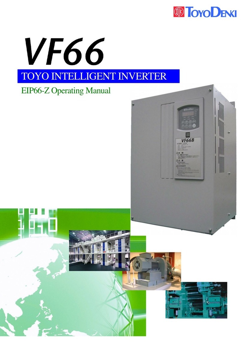
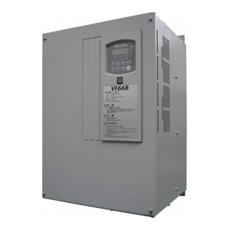
TOYODenki VF66B User manual

TOYO
INTELLIGENT
INVERTER
Operating Manual
~Basic Operation~

VF66BOperatingManual(BasicOperation)
1
Foreword
ThankyouforpurchasingourTOYOVF66Binverter.
Thisinstructionmanualisdesignedtoexplainthecorrectproceduresforinstalling,wiringandoperatingTOYO
VF66Binverter.Carefullyreadthisinstructionmanualbeforeuse.
TOYOVF66Binverterhasmanyspecialfeaturesinadditiontobasicfunctioninordertoaccommodatewidevariety
ofapplicationsandmaximizeperformanceofthesystem.ForthespecialfeatureofVF66B,pleaserefertothe
valuestatedinthededicatedinstructionmanualsortestdatareport.

VF66BOperatingManual(BasicOperation)
2
Safety
For safety
Beforeinstalling,operating,maintainingandinspectingtheinverter,pleasereadthismanualandallotherappendices
thoroughlyinordertogetfamiliarizewiththefeatureoftheinverter,safelyinformationandcorrecthandling.Inthis
manual,thesafetyinstructionsareclassifiedintotwolevels:DANGERandCAUTION.Thesesignshaveimportantinstructions.
Pleasefollowtheinstructionswithoutfail.
DANGERIndicatesahazardoussituationwhichwillresultindeathorseriousinjuryiftheinverter
ishandledimproperly.
CAUTION
Indicatesahazardoussituationwhichmayresultinmoderateorminorinjuryoronlyin
properlydamageiftheinverterishandledimproperly.However,suchasituationmaylead
seriousaccidentsdependingoncircumstances.
Thesesignalwordsindicateimportantinstructions.Followtheinstructionswithoutfail.
CAUTION[Installation]
zInstalltheinverteronametallicornonflammablesurface.
Otherwise,itmaycauseafire.
zDonotplaceflammablematerialsneartheinverter.
Doingsomaycauseafire.
zDonotcarrytheinverterbythefrontcover.
Theinvertermaydropandcausepersonalinjury.
zInstalltheinverteronasurfacethatwithstandsitsweight.
Otherwise,itmaydropandcausepersonalinjury.
zDonotinstalloroperatetheinverterifitisdamagedorhaveanyofitspartsmissing.
Operatingtheinverterinsuchastatemaycausepersonalinjury.
DANGER[Wiring]
zBeforewiring,makesurethattheinputpowerisoff.
Failuretodosomaycauseanelectricshockorafire.
zConnecttheearthwiresurely.
Failuretodosomaycauseanelectricshockorafire.
zTheinvertershallbewiredbyelectricengineeringtechnicians.
Wiringbyunauthorizedpersonsmaycauseanelectricshockorafire.
zWiretheinverterafterinstallingthemainbody.
Failuretodosomaycauseanelectricshockorafire.

VF66BOperatingManual(BasicOperation)
3
CAUTION[Wiring]
zDonotconnectACpowertotheoutputterminals(U,V,andW).
Doingsomaycauseaninjuryorafire.
zCheckthattheratedvoltageoftheproductisidenticalwiththevoltageofACpower.
Ifnot,injuryorafiremayoccur.
zDonotconnectaresistancedirectlytotheDCterminal○
+1orbetween○
+2and○
−or○
+1and○
+2.
Doingsomaycauseafire.
zForgroundfaultprotection,connectthededicatedearthleakageprotectionrelayortheearthleakagebreakerforthe
invertertotheinverterinput(R,S,and,T).
Failuretodosomaycauseanelectricshockorafire.
DANGER[Operation]
zTurnontheinputpowerafterfittingthefrontcover.Donotremovethecoverwhilepowerison.
Doingsomayexposeyoutoshockhazard.
zDonotoperateanyswitchwithwethands.
Doingsomayexposeyoutoshockhazard.
zDonottouchtheinverterterminalwhilepowerisoneveniftheinverterisinthestoppedstate.
Doingsomayexposeyoutoshockhazard.
zThestopbuttoniseffectiveonlywhentheuseofitsfunctionhasbeenspecified.Separatelyprepareanemergencystop
switch.
Failuretodosomaycauseaninjury.
zIfthealarmisresetwiththeoperationsignalkeptinput,theinverterwillsuddenlyrestart.Resetthealarmaftermaking
surethattheoperationsignalisoff.Failuretodosomaycausepersonalinjury.
CAUTION[Operation]
zTheradiatingfinandtheradiatingresistancearehot.Donottouchthem.
Doingsomaycauseaburn.
zTheinvertercanbesettooperateinawiderangeofspeed.Operatetheinverteraftersufficientlycheckingtheallowable
rangeofthemotorandthemachine.
Failuretodosomaycauseapersonalinjury.
zIfaholdingbrakeisnecessary,separatelyprepareit.
Failuretodosomaycausepersonalinjury.
DANGER[Maintenance, inspection and replacement of parts]
zBeforeinspectingtheinverter,turnofftheinputpower,andwaitfor10minutesormoretomakesurethatthemotoris
stopped.
ChecktheDCvoltagebetween○
+and○
−or○
+2and○
−toconfirmthatthevoltageis30Vorless.Failuretodosomay
causeanelectricshock,personalinjuryandafire.
zCheckthattheratedvoltageoftheproductisidenticalwiththevoltageofACpower.
Ifnot,personalinjury,electricshock,ordamagedpartmayoccur.
zUnauthorizedpersonsshallnotmaintainorinspecttheinverterorreplaceitsparts.
Formaintenanceandinspection,useinsulatedtools.
Ifnot,maycauseanelectricshockorpersonalinjury.

VF66BOperatingManual(BasicOperation)
4
DANGER[Other]
zNevermodifytheinverter.
Doingsomaycauseanelectricshockorpersonalinjury.
CAUTION[General precautions]
Allillustrationsgiveninthisinstructionshowtheinverterfromwhichthecoversorsafetyshieldshavebeenremovedto
illustratethedetails.Beforeoperatingtheinverter,returnthecoversandshieldstotheirpositionsasspecified,andoperate
inaccordancewiththemanual.
Thesesafetyprecautionsandspecificationsstatedinthemanualsaresubjecttochangewithoutnotice.

VF66BOperatingManual(BasicOperation)
5
Tableofcontents
Safety............................................................................................................................................................................................... 2
For safety......................................................................................................................................................................................... 2
Chapter 1 Application ............................................................................................................................................................ 7
1.1. Check of package and inspection at the time of purchase ........................................................................................ 7
Chapter 2 Operation............................................................................................................................................................... 9
2.1. Operation at Power-on..................................................................................................................................................... 9
2.2. Operation method of console panel(SET66-Z) .......................................................................................................... 11
2.3. Confirmationofoperationconditionbymonitor.................................................................................................14
Chapter 3 Operation of V/f mode........................................................................................................................................ 16
3.1. Outline of operation........................................................................................................................................................16
3.2. Operation by console panel(SET66-Z) ........................................................................................................................17
3.2.1. Variable frequency driving...............................................................................................................................17
3.2.2. Changing acceleration and deceleration time.............................................................................................. 18
3.2.3. Changing rotation direction ............................................................................................................................19
3.2.4. Inching operation...............................................................................................................................................19
3.2.5. Changing frequency of inching operation.....................................................................................................20
3.2.6. Changing acceleration and deceleration time of inching operation......................................................... 21
3.3. List of monitor items of V/f mode.................................................................................................................................22
3.4. Operation and stop by external contact .....................................................................................................................24
3.5. Changing rotation speed by voltage setting device/variable resistor................................................................. 26
3.6. Auto tuning......................................................................................................................................................................28
3.6.1. Auto tuning.........................................................................................................................................................28
3.6.2. Condition of auto tuning ..................................................................................................................................29
3.6.3. Method of auto tuning ......................................................................................................................................31
3.7. List of parameter to change for setting by simple mode of V/f mode.................................................................32
Chapter 4
Operation of induction motor vector mode
......................................................................................................................... 36
4.1. Characteristics of induction motor vector mode .......................................................................................................36
4.2. Outline of operation........................................................................................................................................................36
4.3. Changing to induction motor vector mode.................................................................................................................37
4.4. Auto tuning......................................................................................................................................................................38
4.4.1. Auto tuning.........................................................................................................................................................38
4.4.2. Condition of auto tuning ..................................................................................................................................39
4.4.3. Method of auto tuning ......................................................................................................................................42
4.5. Operation by console ......................................................................................................................................................44
4.5.1. Changing motor rotation speed ...................................................................................................................... 44
4.5.2. Changing acceleration and deceleration time.............................................................................................. 45
4.5.3. Changing rotation direction ............................................................................................................................46

VF66BOperatingManual(BasicOperation)
6
4.5.4. Inching operation...............................................................................................................................................46
4.5.5. Changing rotation speed of inching operation.............................................................................................47
4.5.6. Changing acceleration and deceleration time of inching operation......................................................... 48
4.6. List of monitor item of induction motor vector mode...............................................................................................49
4.7. List of parameter to change for setting by simple mode of induction motor vector mode................................51
Chapter 5
Operation of ED motor vector mode
....................................................................................................................... 56
5.1. Characteristics of ED motor vector mode ..................................................................................................................56
5.2. Outline of operation........................................................................................................................................................56
5.3. Changing to ED motor vector mode............................................................................................................................58
5.4. Auto tuning......................................................................................................................................................................59
5.4.1. Auto tuning.........................................................................................................................................................59
5.4.2. Condition of auto tuning ..................................................................................................................................60
5.4.3. Method of auto tuning ......................................................................................................................................63
5.5. Operation by console ......................................................................................................................................................66
5.5.1. Changing motor rotation speed ...................................................................................................................... 66
5.5.2. Changing acceleration and deceleration time.............................................................................................. 67
5.5.3. Changing rotation direction ............................................................................................................................68
5.5.4. Inching operation...............................................................................................................................................68
5.5.5. Changing rotation speed of inching operation.............................................................................................69
5.5.6. Changing acceleration and deceleration time of inching operation......................................................... 70
5.6. List of monitor items of ED motor vector mode........................................................................................................71
5.7. List of parameter to change for setting by simple mode of ED motor vector mode........................................... 73
Chapter 6 Contact us............................................................................................................................................................ 78

VF66BOperatingManual(BasicOperation)
7
Chapter 1 Application
1.1. Check of package and inspection at the timeof purchase
Whentheproductarrives,checkthefollowings.
(1) Checkofpackage
DoesthepackageincludeinvertermainbodyandbrochureandCD‑ROMofinstruction?
Invertermainbody
Manual<Brochure&CD‑ROM>
Manual
(2) Arespecificationcontents,accessories,spareparts,andoptiondeliveredasperorder?
Checkthetypeofinverterunitbythelogoonthecoversurface.
Logo

VF66BOperatingManual(BasicOperation)
8
Displaysampleonthecoversurface
sourcevoltage
Spec.ofinput
VF66B
VF66B-7R544
TYPE VF66B‑7R544‑W1
APPL. QA1
INPUT
3Φ380〜460V 50/60Hz
OUTPUT 7.5kW 17.0A
WEIGHT 5.5kg
SER. No. QC123456789‑001
◇
!危 険
・・・・・・・・・・・・・・・
・・・・・・・・・・・・・・・
・・・・・・・・・・・・・・・
△
!注 意
・・・・・・・・・・・・・・・
・・・・・・・・・・・・・・・
△
!DANGER
・・・・・・・・・・・・・・・
・・・・・・・・・・・・・・・
・・・・・・・・・・・・・・・
・・・・・・・・・・・・・・・
・・・・・・・・・・・・・・・
Invertertype(ItshowsVF66series.)
Inverteroutputcapacityandcurrent
TypeVF66B−7R544−W1
Voltageclass 22:200Vclass
44:400Vclass
Outputcapacity7.5kW
Type
Mark
SerialNo.
Weight
(3) Isthereanydamageduringtransportation?
(4) Isthereanyloosenessordropoutofscrews?
Pleaseinformusordealerifthereisanydefault.
CAUTION[Precautions]
Read“Instructionmanual”carefullybeforeuseanduseproperly.
Ourinverterisnotdesignedandmanufacturedtouseequipmentorsystemunderthefatalconditiontohuman.
Pleasecontactoursalesifyouusetheproductstatedinthisbrochureforspecialpurposesuchasmovingvehicle,medical,
aerospace,nuclearcontrol,submarinerepeaterorsystem.
Thoughthisproductismanufacturedunderthestrigentqualitycontrol,forapplicationtoimportantfacilitieswhichinvolves
humanlivesandfacilitiesestimatedseriouslossduetothefailureoftheinverter,setthefail‑safedevicenottoleadserious
accident.
Pleasecontactusifyouuseloadotherthanthree‑phaseACtraction.
Thisproductneedselectricconstruction.Electricconstructionshallbeperformedbytheexperts.

VF66BOperatingManual(BasicOperation)
9
Chapter 2 Operation
2.1. Operation at Power-on
WhenVF66Bispoweredon,thefollowingdisplayappearsontheconsolepanelmonitor.
1.5sec
②Then inverter capacity and voltage are displayed for 1.5 seconds. From left inverter
capacity and feeding voltage are shown. Decimal point is shown by r. Also if
voltage class is 200V class, it displays 22, and if voltage class is 400V class, it
displays 44.
<In case of left figure, it is 3.7kW200Vclassinverter.>
③Then the mark distinguishing between setting block and inverter mode is displayed.
In the order corresponding to the digit at the far left,
[Inverter mode of first setting block] [-] [Second setting inverter mode] [Current setting block]]
aremeant.
Invertermodeisthefollowingmark.
o:ItshowsinductionmotorV/fmode.
V:Itshowsinductionmotorvectormode.
E:ItshowsEDmotorvectormode.
<Incaseofleftfigure,V/fmodeissetinFirstsettingblock,inductionmotorvector
modeissetinsecondsettingmodeandcurrentsettingblockisfirstsettingblock.
>
①Inverter type displays for 1.5 seconds.
1.5sec
Cap. Volt
First
setting
block
Second
setting
block
Currentsetting
block
WeexplainoperationofinductionmotorvectormodeinChapter4 Operationofinductionmotorvectormodeand
operationofEDmotorvectormodeinChapter5OperationofEDmotorvectormode.
※EDmotorshowsourpermanentmagnetembeddedsynchronousmotor.
VF66Bcansetthefollowing3typesofinvertermode.
Mark Invertermode Description
o InductionmotorV/fmode Ratioofvoltageandfrequencyofinductionmotorbecomesconstantandfrequencycontrolcanbe
performed.
V Inductionmotorvectormode Highspeedandaccuracyofspeedandtorquecontrolofinductionmotorcanbeperformed.
E EDmotorvectormode HighspeedandaccuracyofspeedandtorquecontrolofEDmotorcanbeperformed.
※AtinitialstateinductionmotorV/fmodeisset.
r/min
Hz
A
V
FNC
DIR REV
ALM
RUN
JOG
Consolepanel
monitor
FNC
RESET
FWD
JOG
START
STOP
REV
MONI
SET
→
Invertermotor

VF66BOperatingManual(BasicOperation)
10
TherearefirstsettingblockandsecondsettingblockinVF66B,andeachblockcansetindividualinverter
modeandparameterrespectively.Consolepaneldisplayatpoweredoncanbecheckedatpresentwhichofblock
isusedfirstsettingblockorsecondsettingblockorwhichofthreeinvertermodeisusedinfirstsetting
blockandsecondsettingblock.
SeeFullmodeinstructionmanualforchangemethodofusedsettingblock(firstsettingblock,second
settingblock).Howeversimplemodedescribedinthismanualcannotbeused.
TherearetwomodesofsimpleanddetailedinVF66B.
Description
Simplemode Thismodecandisplayandchangeonlynecessaryparameterforbasicoperation.
Fullmode Thismodecandisplayandchangeallparameter.
Thismanualdescribesoperationofsimplemode.SeeFullmodeinstructionmanualforchangemethodtoFullmode,
etc.
※・Forparameterwhichcanbedisplayedandchangedbysimplemode;See
Chapter3 3.7 ListofparameterwhichcanbechangedforsettingbysimplemodeofV/fmode
Chapter44.7 Listofparameterwhichcanbechangedforsettingbysimplemodeofinductionmotorvector
mode
Chapter55.7 ListofparameterwhichcanbechangedforsettingbysimplemodeofEDmotorvectormode
・SeeFullmodeinstructionmanualforparameterwhichcanbedisplayedandchangedbyFullmode.
SimpleandFullmode
1
Firstsettingblockandsecondsettingblock
ロック
・
第
2
設定
ブロック
について

VF66BOperatingManual(BasicOperation)
11
2.2. Operation method of console panel(SET66-Z)
VF66Bincludes5digitsLEDindicatorandconsolepanel(SET66‑Z)equippedwith0operationkeybuttons,unit
LEDandstatusdisplayLEDasstandardequipmentandcanperformoperation,readandwriteeachfunctionsetting
data,displaymonitoringoperatingconditionandprotectioncontentsatprotectionoperation.
●Panelsurface
r/min
Hz
A
V
FNC
DIR REV
ALM
RUN
JOG
FNC
RESET
FWD
JOG
START
STOP
REV
MONI
SET
●LEDwindow:7segments5digitsdisplay
Characterandvaluedisplay
Operationmonitor/Mark(No.)/Functionselectionandsettingdata
/protectoperation/Displayofprotectionhistory
●Unitdisplay(LEDdisplay)
●Statusdisplay(LEDdisplay)
FNC:LightedwhenFNCmode(Functionsettingmode)isselected.
DIR:Lightedwheneither[START]or[JOG/→]keyofconsolepanelis
selectedforconsolepaneloperation.
REV:LightedwhenREV(reverse)isselected.
ALM:Lightedwhencumulativeoperationaltimeexceedsthepredetermined
time.
RUN:Lightedduringoperationofinverter.(Duringslowingdownand
stop,itislightedduringDCbraking.)
JOG : Lighted when inverter is inching operation(RUN is lighted
simultaneously.)
●Operationkey
START
FWD
REV
SET
FNC
MONI
RESET
STOP
JOG
<AtFNC(Functionsetting)mode>
・Fixselectionofsettingnumber.
・Writesettingdata.
<AtMONI(Monitor)mode>
・Switchmonitoritems.
<Atprotectionoperation>
・Read1pointtracebackdata.
SwitchMONImodeandFNC mode
<AtFNC(Functionsetting)mode>
・SwitchtoMONImode.
<AtMONI(Monitor)mode>
・SwitchtoFNCmode.
<AtMONI(Monitor)mode>
・When console panel[START]or [JOG/ → ]is
effective,switchforward/reversecommand.
Lighted when REV(LED)is reverse command
selection.
<AtMONI(Monitor)mode>
・Inverteroperateswhenconsoleissetfor
operationcommandsettingplaceselection.
<AtFNC(Functionsetting)mode>
・WhensettingNo.anddataareset,numberof
selecteddigitisincreasedto+1.
(By0→1→・・・・・・→9
→ ‑(minus) → 「 0」 of orders number is
changed.)
<AtMONI(Monitor)mode>
・Switch of monitor items.(See Chapter2 2.3
confirmation of operation condition by monitor for
details..)
<AtFNC(Functionsetting)mode>
・WhensettingNo.anddataareset,numberof
selecteddigitisincreasedto−1.
( By0 → ‑(minus) → 9 → ・ ・・ ・ ・・
→1→0ofordersnumberischanged.)
<AtMONI(Monitor)mode>
・Switchofmonitoritems.
(SeeChapter22.3 confirmationofoperation
conditionbymonitorfordetails.)
<AtFNC(Functionsetting)mode>
・Move operated selected digit to1 digit
right.
<AtMONI(Monitor)mode>
・When console is set for inching command
settingplaceselection,inverteroperates.
Duringoperationbyconsolepanel[START]key,
inverter stops. During protect operation,
protectoperationisreset.

VF66BOperatingManual(BasicOperation)
12
Outlineofoperation
Thereare3modesinconsolepanel(SET66‑Z).
①MONI(Monitor)mode
②FNC(Functionsetting)mode
③Protectionoperationdisplaymode
Outlineofoperationisshowninthefollowingfigure.
PowerOn
Checkcapacity,voltage,and
invertermodeof
VF66B.
<MONI(Monitor)mode>
Operationconditionofmotorandinverter
(rotation speed, output torque, output
voltage) is displayed in console panel
monitor(7segments5digitsdisplay).
<Capacity><voltage>
<invertermode>
r/min
Hz
A
V
FNC
DIR REV
ALM
RUN
JOG
FNC
RESET
FWD
JOG
START
STOP
REV
MONI
SET
→
r/min
Hz
A
V
FNC
DIR REV
ALM
RUN
JOG
FNC
RESET
FWD
JOG
START
STOP
REV
MONI
SET
→
Press[MONI/FNC]key.Press[MONI/FNC]key.
<Protectionoperationdisplaymode>
Incaseofprotectionoperation,
・Displayprotectionoperation.
・Display1pointtraceback
See Instruction manual (trouble
shootingandmaintenance)fordetails.
<FNC(Functionsetting)mode>
AtFNC(Functionsetting)modeFNC(LED)
islighted
and necessary parameter for operation of
inverterisset.
Protection
Protection
r/min
Hz
A
V
FNC
DIR REV
ALM
RUN
JOG
FNC
RESET
FWD
JOG
START
STOP
REV
MONI
SET
→
Press[STOP/RESET]key.
※For parameter which can be displayed and changed by simple mode, see “Chapter3 3.7 Listofparameter
whichcanbechangedforsettingbysimplemodeofV/fmode,
“Chapter4 4.7Listofparameterwhichcanbechangedforsettingbysimplemodeofinductionmotorvector
mode,andChapter55.7 ListofparameterwhichcanbechangedforsettingbysimplemodeofEDmotor
vectormode..

VF66BOperatingManual(BasicOperation)
13
Changeparameterbyconsolepanel(SET66‑Z)
Changeparameterbyconsolepanel(SET66‑Z)isshown.
r/min
Hz
A
V
FNC
DIR REV
ALM RUN
JOG
FNC
RESET
FWD
JOG
START
STOP
REV
MONI
SET
→
WhenconsolepanelFNC(LED)isturnedoffalight,press[MONI/FNC]
keytolight
upFNC(LED).
r/min
Hz
A
V
FNC
DIR REV
ALM
RUN
JOG
FNC
RESET
FWD
JOG
START
STOP
REV
MONI
SET
→
0.FrEFbasicsettingareaisdisplayedandcanbemoved
tosettingitemsby[↑][↓]keys.
r/min
Hz
A
V
FNC
DIR REV
ALM
RUN
JOG
FNC
RESET
FWD
JOG
START
STOP
REV
MONI
SET
→
By[JOG/→]
keyshiftoperateddigittorightandchangenumberby
[↑][↓]keys.Aftersettingparameteryouwanttocha
nge,fixby
[SET]key.
<Incaseofleftfigure,setitemsb‑11isset.>
r/min
Hz
A
V
FNC
DIR REV
ALM RUN
JOG
FNC
RESET
FWD
JOG
START
STOP
REV
MONI
SET
→
Changethenumberforthepropernumberby[↑][↓]keyand
fixby
[SET]key.
<Incaseofleftfigure,parameterissetto1.>
r/min
Hz
A
V
FNC
DIR REV
ALM RUN
JOG
FNC
RESET
FWD
JOG
START
STOP
REV
MONI
SET
→
Changedparameterisdisplayedagain.
<Incaseofleftfigure,b‑11isdisplayedbecause
settingitemb‑11isset.>
Press[MONI/FNC]key,andturnoffalightofFNC(LED).MonitoritemssuchasFout
isdisplayedforabout1sec.anddataofmonitoritemsisdisplayed.
r/min
Hz
A
V
FNC
DIR REV
ALM RUN
JOG
FNC
RESET
FWD
JOG
START
STOP
REV
MONI
SET
→
r/min
Hz
A
V
FNC
DIR REV
ALM RUN
JOG
FNC
RESET
FWD
JOG
START
STOP
REV
MONI
SET
→
AareatoSareacanbemovedtoothersettingareawhile
alphabeticalpartisflashingonandoff.
※Forparameterwhichcanbedisplayedandchangedbysimplemode,
SeeChapter3 3.7 ListofparameterwhichcanbechangedforsettingbysimplemodeofV/fmode,
Chapter44.7 Listofparameterwhichcanbechangedforsettingbysimplemodeofinductionmotorvector
mode,andChapter55.7 ListofparameterwhichcanbechangedforsettingbysimplemodeofEDmotor
vectormode.
<Settingminus‑valueinconsolepanel(SET66‑Z)>
By[JOG/→]keymoveoperateddigittofarleftdigit,andchangenumberby[↑]or[↓].
<[↑]keycase>
Itischangedlike0→1→2→・・・・・・→8→9→−,itbecomesminus
after9.
<[↓]keycase>
Itischangedlike0→−→9→・・・・・・→3→2→1,itbecomesminus
after0.

VF66BOperatingManual(BasicOperation)
14
2.3. Confirmationofoperationconditionbymonitor
VF66Bcanmonitordatasuchasmotorrotationspeed,current,andvoltagebyLEDdisplayofconsolepanel.
Selectionofmonitoringitemsisperformedbythefollowingprocedure.
r/min
Hz
A
V
FNC
DIR REV
ALM
RUN
JOG
FNC
RESET
FWD
JOG
START
STOP
REV
MONI
SET
→
WhenconsolepanelFNC(LED)islighted,press[MONI/FNC]keyandturnoffthe
lightofFNC(LED).
r/min
Hz
A
V
FNC
DIR REV
ALM
RUN
JOG
FNC
RESET
FWD
JOG
START
STOP
REV
MONI
SET
→
Acurrentsettingmonitoritemisdisplayedforabout1sec.
<Incaseofleftfigure,outputfrequency(Fout)
issetasmonitor
item.>
r/min
Hz
A
V
FNC
DIR REV
ALM
RUN
JOG
FNC
RESET
FWD
JOG
START
STOP
REV
MONI
SET
→
In1sec,itischangedfordatadisplayofcurrentsettingmonitor
item.<Incaseofleftfigure,itshow
soutputfrequency
(Fout)is0.0[Hz].>
1sec.later
r/min
Hz
A
V
FNC
DIR REV
ALM
RUN
JOG
FNC
RESET
FWD
JOG
START
STOP
REV
MONI
SET
→
Ifyoupressanyof[SET][↑][↓]
key,acurrentsettingmonitor
itemisdisplayed.
r/min
Hz
A
V
FNC
DIR REV
ALM
RUN
JOG
FNC
RESET
FWD
JOG
START
STOP
REV
MONI
SET
→
Ifyoupresseither[SET]or[↑]key,
next monitor item is shifted and
displayed.
In this case, it is switched to
frequencysettingvalue(Fref).
r/min
Hz
A
V
FNC
DIR REV
ALM
RUN
JOG
FNC
RESET
FWD
JOG
START
STOP
REV
MONI
SET
→
Ifyoupress[↓]key,nextmonitor
itemisshiftedanddisplayed.
In this case, it is switched to
protectionhistorydisplay(trbLE).

VF66BOperatingManual(BasicOperation)
15
Allmonitoritemsare24items.Bypressing[SET]or[↑]keyand[↓]key,eachitemsareswitchedasfollows.
[SET]or[↑]keyand[↓]isswitchedinthereversedirection.
Forlistofmonitoritemsofeachmode,see
V/fmode・・・Chapter3 3.3 ListofmonitoritemsofV/fmode
Inductionmotorvectormode・・・Chapter4 4.6 Listofmonitoritemsofinductionmotorvectormode
EDmotorvectormode・・・Chapter5 5.6 ListofmonitoritemsofEDmotorvectormode
●Incaseofpressing[SET]or[↑]key(Eg.:V/fmodecase)
r/min
Hz
A
V
FNC
DIR REV
ALM
RUN
JOG
FNC
RESET
FWD
JOG
START
STOP
REV
MONI
SET
→
●Incaseofpressing[↓]key(Eg:V/fmodecase)
r/min
Hz
A
V
FNC
DIR REV
ALM
RUN
JOG
FNC
RESET
FWD
JOG
START
STOP
REV
MONI
SET
→

BasicOperation(V/fmode)
16
Chapter 3 Operation of V/f mode
3.1. Outline of operation
Thefollowingsshowaseriesofoperationusingconsole.
See“Chapter33.2.1Rotatingmotorbydesignatedfrequency”fordetailedoperationsuchasfrequencycommand
andchangeofaccelerationanddecelerationtime.
Prep.andwiring
Checkcapacity,voltage,
andinvertermodeforuse.
Poweredon
Checkcapacity,voltage,and
invertermodeofVF66B.
Settingfrequencycommand,
accelerationanddecelerationtime
Operation/Stop
Performconnectionofinverterandpowersource(R,S,T),inverterand
motor(U,V,W)andearth(
).
<Capacity><Voltage>
<invertermode>
r/min
Hz
A
V
FNC
DIR REV
ALM
RUN
JOG
FNC
RESET
FWD
JOG
START
STOP
REV
MONI
SET
→
Pressconsolepanel[MONI/FNC]key,lightFNC[LED]andset
0.FrEF(Frequency command)and3.Acc1(acceleration
time).SeeChapter3 3.2.1 Rotatingmotorbydesignated
frequencyorlaterfordetails.
r/min
Hz
A
V
FNC
DIR REV
ALM
RUN
JOG
FNC
RESET
FWD
JOG
START
STOP
REV
MONI
SET
→
Pressconsolepanel[MONI/FNC]keyandturnoffthelight
ofFNC[LED],bypressing[START]keyoperationisstarted
bysettingfrequencycommand(0.FrEF),acceleration
time(3.Acc1).Operationstopsbypressing[STOP/RESET]
key.
Changesetting

BasicOperation(V/fmode)
17
3.2. Operation by console panel(SET66-Z)
3.2.1. Variablefrequencydriving.
Thefollowingsshowcontrollingrotaitionalspeedofmotorbydesignatedfrequency.
r/min
Hz
A
V
FNC
DIR REV
ALM
RUN
JOG
FNC
RESET
FWD
JOG
START
STOP
REV
MONI
SET
→
r/min
Hz
A
V
FNC
DIR REV
ALM
RUN
JOG
FNC
RESET
FWD
JOG
START
STOP
REV
MONI
SET
→
WhenconsolepanelFNC(LED)isturnedoffalight,press[MONI/FNC]keyandlight
upFNC(LED).
r/min
Hz
A
V
FNC
DIR REV
ALM
RUN
JOG
FNC
RESET
FWD
JOG
START
STOP
REV
MONI
SET
→
By[↑][↓]keyselect0.FrEF(frequencycommand).Fixby
[SET]key.
r/min
Hz
A
V
FNC
DIR REV
ALM
RUN
JOG
FNC
RESET
FWD
JOG
START
STOP
REV
MONI
SET
→
r/min
Hz
A
V
FNC
DIR REV
ALM
RUN
JOG
FNC
RESET
FWD
JOG
START
STOP
REV
MONI
SET
→
By[JOG/→]keyshifttheoperateddigittorightandchange
number(frequency)by[↑][↓]keyandfixby[SET]key.
※Settingareabecomes‑60.0to60.0[Hz]atinitialsettingcondition.
r/min
Hz
A
V
FNC
DIR REV
ALM
RUN
JOG
FNC
RESET
FWD
JOG
START
STOP
REV
MONI
SET
→
Afterfixingfrequencyby[SET]key,0.FrEFisdisplayedagain.
Press[MONI/FNC]keyandturnoffthelightofFNC(LED).Monitor
itemssuchasFoutisdisplayedforabout1second.
※SeeChapter3 3.3 ListofmonitoritemofV/fmodefor
detailsofmonitoritems.
1sec. later
1secondlater,displayofconsoleshowspresentsettingmonitor
item.
<
Incaseofleftfigure,itshowsoutputfrequencyis0.0[Hz].
>
r/min
Hz
A
V
FNC
DIR REV
ALM
RUN
JOG
FNC
RESET
FWD
JOG
START
STOP
REV
MONI
SET
→
Whenyoupress[START]key,operationisstartedandmotorisbegun
torotate,frequencyischangedtopre‑settingfrequency.During
operation,consoleshowspresentsettingmonitoritem.
<Incaseofleftfigure,itshowspresentoutputfrequencyis
0.5[Hz].>
※Whenmotordoesnotrotateevenifyoupress[START]key,change
frequencycommand(0.FrEF).Frequencycommandcanbechanged
duringoperation.
r/min
Hz
A
V
FNC
DIR REV
ALM
RUN
JOG
FNC
RESET
FWD
JOG
START
STOP
REV
MONI
SET
→
Whenyoupress[STOP/RESET]key,operationandrotationofmotor
stops.
<Incaseofleftfigure,itshowspresentoutputfrequencyis
0.0[Hz].>
<Settingarea,settingresolution,initializationdataandunitoffrequencycommand>
Display Content Settingarea Resolution
Initialization
data Unit
0.FrEF Frequencycommand − Maximum frequency (A‑00)to
Maximumfrequency(A‑00) 0.1 0.5 Hz
※See“Chapter3 3.6.2 Conditionofautotuning”forMaximumfrequency(A‑00).

BasicOperation(V/fmode)
18
3.2.2. Changingaccelerationanddecelerationtime
Thefollowingsshowchangingaccelerationanddecelerationtime.
r/min
Hz
A
V
FNC
DIR REV
ALM
RUN
JOG
FNC
RESET
FWD
JOG
START
STOP
REV
MONI
SET
→
Whenyoupress[STOP/RESET]key,operationandrotationofmotor
stops.
<
Incaseofleftfigure,itshowscurrentoutputfrequencyis
0.0[Hz].>
r/min
Hz
A
V
FNC
DIR REV
ALM
RUN
JOG
FNC
RESET
FWD
JOG
START
STOP
REV
MONI
SET
→
WhenconsoleFNC(LED)isturnedoffalight,press[MONI/FNC]keyandlightupFNC
(LED).
r/min
Hz
A
V
FNC
DIR REV
ALM
RUN
JOG
FNC
RESET
FWD
JOG
START
STOP
REV
MONI
SET
→
By [JOG/ → ]key shift the operated digit to the right and
by[↑][↓]keychangenumber(Accelerationanddecelerationtime)
andfixby[SET]key.
r/min
Hz
A
V
FNC
DIR REV
ALM
RUN
JOG
FNC
RESET
FWD
JOG
START
STOP
REV
MONI
SET
→
1sec.later
1secondlater,itischangedfordatadisplayofcurrentsetting
monitoritem.
<Incaseofleftfigure,itshowsoutputfrequencyis0.0[Hz].
r/min
Hz
A
V
FNC
DIR REV
ALM
RUN
JOG
FNC
RESET
FWD
JOG
START
STOP
REV
MONI
SET
→
Whenyoupress[START]key,operationisstartedandmotorisbegun
torotate,itacceleratesanddeceleratesbysettingacceleration
anddecelerationtime
.Duringoperation,dataofcurrentsetting
monitoritemisdisplayed.
<
Incaseofleftfigure,itshowscurrentoutputfrequencyis0.5[Hz].
>
※
Accelerationanddecelerationtimecanbechangedevenifduringoperation.
<
Accelerationtime
>
r/min
Hz
A
V
FNC
DIR REV
ALM
RUN
JOG
FNC
RESET
FWD
JOG
START
STOP
REV
MONI
SET
→
By[ ↑ ][ ↓ ]key
select3.Acc1
(acceleration
time(1)
).Fixby[SET]key.
r/min
Hz
A
V
FNC
DIR REV
ALM
RUN
JOG
FNC
RESET
FWD
JOG
START
STOP
REV
MONI
SET
→
By[ ↑ ][ ↓ ]key
select4.dEc1
(Deceleration
time(1)
).Fixby[SET]key.
<
Deceleration
time
>
r/min
Hz
A
V
FNC
DIR REV
ALM
RUN
JOG
FNC
RESET
FWD
JOG
START
STOP
REV
MONI
SET
→
Press[MONI/FNC]keyandturnoffthelightofFNC(LED).Monitor
itemsuchasFoutisdisplayedforabout1second.
※SeeChapter3 3.3 ListofmonitoritemofV/fmodefor
detailsofmonitoritem.
r/min
Hz
A
V
FNC
DIR REV
ALM
RUN
JOG
FNC
RESET
FWD
JOG
START
STOP
REV
MONI
SET
→
After fixing acceleration
timeby[SET]key,3.Acc
isdisplayedagain.
r/min
Hz
A
V
FNC
DIR REV
ALM
RUN
JOG
FNC
RESET
FWD
JOG
START
STOP
REV
MONI
SET
→
<
Accelerationtime
> <
Decelerationtime
>
Afterfixingdecelerationtime
by[SET]key,4.dEc1is
displayedagain.
<Settingarea,settingresolution,initializationdata,andunitofaccelerationanddecelerationtime>
Display Content Settingarea
(Selectionitems) resolution
Initialization
data Unit
3.Acc1 Accerelationtime(1) 0.0to3600.0 0.1 30.0 sec
4.dEc1 Decelerationtime(1) 0.0to3600.0 0.1 30.0 sec

BasicOperation(V/fmode)
19
Operationofmotorisasshowninthefigure.Whenaccelerationtimeisbigger,gradientoftime‑frequency
islessandtimetoMaximumfrequencyislonger.Ontheotherhand,whenaccelerationisless,gradientof
time‑frequencyisbiggerandtimetoMaximumfrequencyisshorter.
※WhencurrentistoobigataccelerationorDCpartovervoltage(oV)operatesatdeceleration,makesetting
valueofaccelerationanddecelerationtimelonger.
Frequency
Time
「A‑00」
Maximumfrequency
「4.dEc1」
Deceleration
「3.Acc1」
Acceleration
※See“Chapter33.6.2 Conditionofautotuning”forMaximufrequency(A‑00).
3.2.3. Changingrotationdirection
Therearetwomethodsforchangingrotationdirection.
①Methodbypressing[FWD/REV]keyofoperationkey
r/min
Hz
A
V
FNC
DIR REV
ALM
RUN
JOG
FNC
RESET
FWD
JOG
START
STOP
REV
MONI
SET
→
・CheckFNC(LED)isturnedoffalight.
・Incaseoflighting,press[MONI/FNC]keytoturnoffalight.
・Duringoperationandstop,bypressing[FWD/REV]keyrotationdirectionof
motorcanbechanged.
※REV(LED)islighted.
※
DuringlightingupREV(LED),bypressing[FWD/REV]key,REV(LED)isturnedoff.
②Inputofminuscommand
InChapter3 3.2.1 Rotatingmotorbydesignatedfrequency,rotationdirectionofmotorcanbechanged
by turning 0.FrEF(frequency command) minus. SeeChapter2 2.2 Operation procedure of console
panel(SET‑Z)forsettingminus.
3.2.4. Inchingoperation
r/min
Hz
A
V
FNC
DIR REV
ALM
RUN
JOG
FNC
RESET
FWD
JOG
START
STOP
REV
MONI
SET
→
・CheckFNC(LED)isturnedoffalight.
・Incaseoflighting,bypressing[MONI/FNC]keyturnoffalight.
・Bypressing[JOG/→]key,inchingoperationisperformed.
※RUN(LED)andJOG(LED)arelightedup.
・Byreleasing[JOG/→]keyinchingoperationstops.
Other manuals for VF66B
3
Table of contents
Other TOYODenki Inverter manuals
Popular Inverter manuals by other brands

Growatt
Growatt WIT 50-100K-US user manual

Ginlong
Ginlong Solis-100K-5G Installation and operation manual

SEW-Eurodrive
SEW-Eurodrive MOVITRAC LTP-B operating instructions

Sungrow
Sungrow SG5.0RS-ADA user manual

Unitor
Unitor UWI-230TP Assembly & preparation manual

FRONIUS
FRONIUS IG Plus USA operating instructions