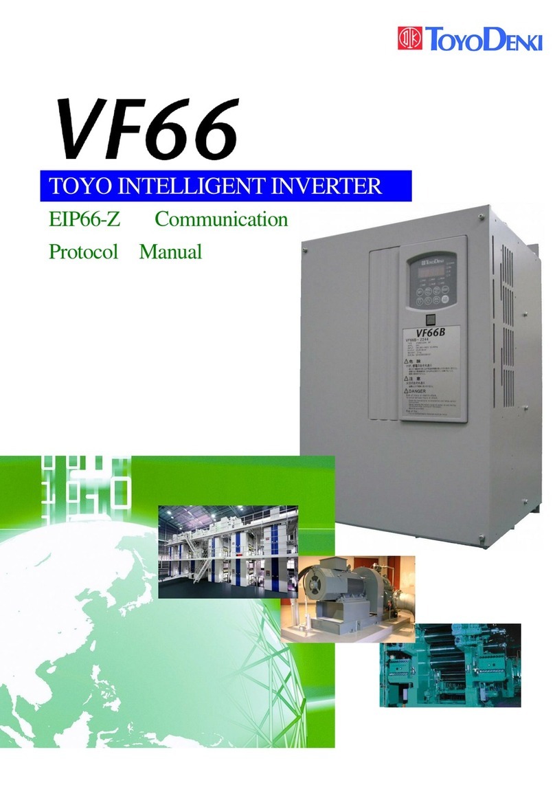
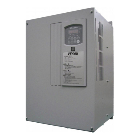
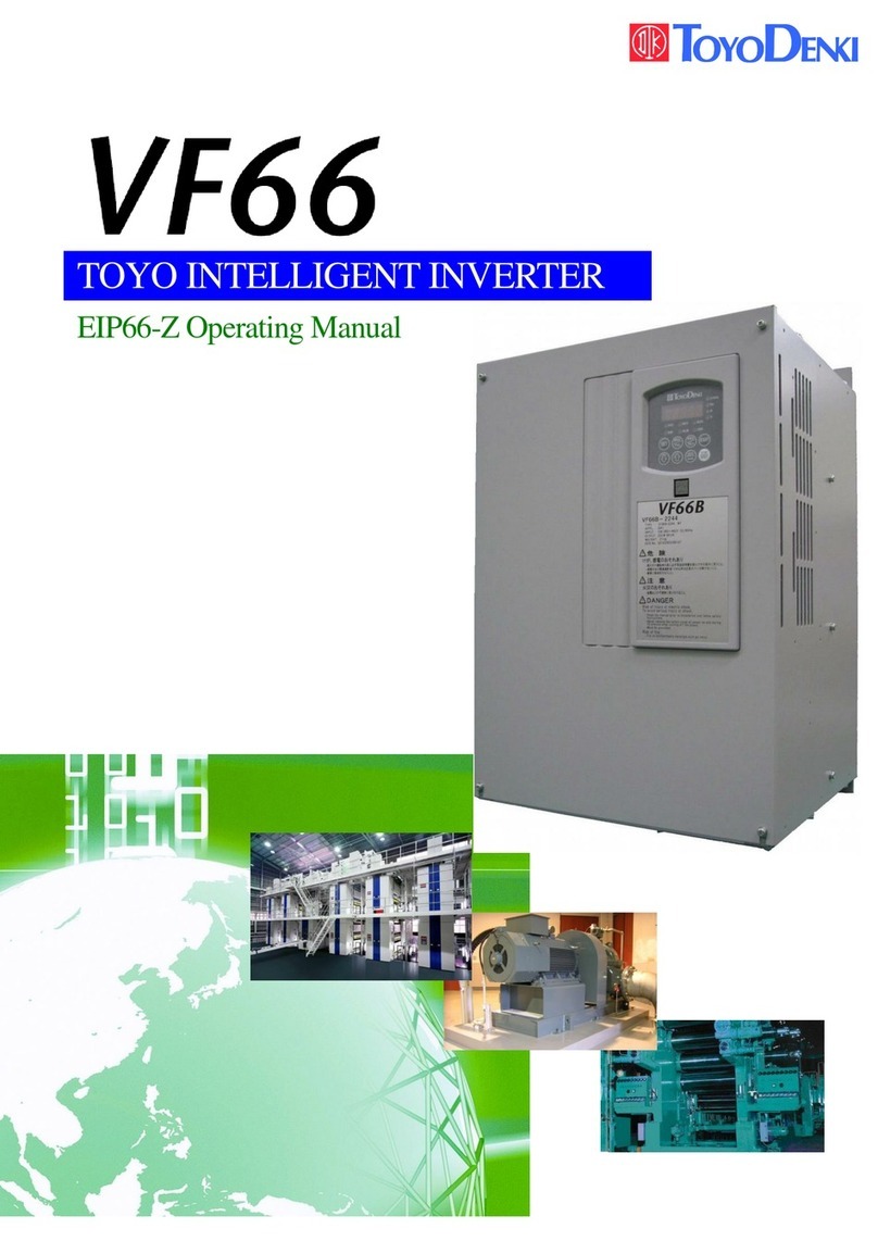
TOYODenki VF66B User manual

TOYO
INTELLIGENT
INVERTER
Operating Manual
~Induction Motor Vector Control Mode ~

Inductionmotorvectormode
1
Foreword
ThankyouforchoosingTOYOinverterproduct.ThisinstructionmanualisforTOYOVF66BinverterFULLmode
(Inductionmotorvectormode).BeforeusingTOYOVF66BinverterinInductionmotorvectormode,pleaseread
asetofinstructionmanuals(Installation,Basicoperation,TroubleshootingandMaintenance)togetfamiliarize
withthefeatureofTOYOVF66Binverterandusethismanualforthosefunctionswhicharenotcoveredinan
instructionmanual(basicoperationedition).
TOYOVF66Binverterhasmanyspecialfeaturesinadditiontobasicfunctioninordertoaccommodatewidevariety
ofapplicationsandmaximizeperformanceofthesystem.ForthespecialfeatureofVF66B,pleaserefertothe
valuestatedinthededicatedinstructionmanualsortestdatareport.

Inductionmotorvectormode
2
Pleasereadbeforeuse
For safety
Beforeinstalling,operating,maintainingandinspectingtheinverter,pleasereadthismanualandallotherappendices
thoroughlyinordertogetfamiliarizewiththefeatureoftheinverter,safelyinformationandcorrecthandling.Inthis
manual,thesafetyinstructionsareclassifiedintotwolevels:DANGERandCAUTION.Thesesignshaveimportantinstructions.
Pleasefollowtheinstructionswithoutfail.
DANGER
Indicatesahazardoussituationwhichmayresultindeathorseriousinjuryifitishandled
improperly.
CAUTION
Indicatesahazardoussituationwhichmayresultinmoderateorminorinjuryoronlyin
propertydamageifitishandledimproperly.However,suchasituationmayleadtoserious
consequencesdependingoncircumstances.
CAUTION[Installation]
zInstalltheinverteronametallicornon‑flammablesurface.
Otherwise,itmaycauseafire.
zDonotplaceflammablematerialsneartheinverter.
Doingsomaycauseafire.
zDonotcarrytheinverterbythefrontcover.
Theinvertermaydropandcausepersonalinjury.
zInstalltheinverteronthesurfacethatwithstandsitsweight.
Otherwise,itmaydropandcausepersonalinjury.
zDonotinstalloroperatetheinverterifitisdamagedorhaveanyofitspartsmissing.
Operatingtheinverterinsuchastatemaycausepersonalinjury.
DANGER[Wiring]
zBeforewiring,makesurethepowerisOFF.
Failuretodosomaycauseanelectricshockorafire.
zMakesuretoconnectgroundingwire.
Failuretodosomaycauseanelectricshockorafire.
zWiringmustbedonebyskilledtechnicians.
Wiringbyunauthorizedpersonsmaycauseanelectricshockorafire.
zWiretheinverterafteritisinstalled.
Failuretodosomaycauseanelectricshockorafire.
CAUTION[Wiring]
zDonotconnectACpowertotheoutputterminals(U,VorW).
Doingsomaycauseaninjuryorafire.
zMakesurethattheratedvoltageofthedeviseisconformedtothevoltageofACpower.
Ifnot,injuryorafiremayoccur.
zDonotconnectaresistancedirectlytotheDCterminal○
+1orbetween○
+2and○
−or○
+1and○
+2.
Doingsomaycauseafire.
zConnectadesignatedground‑faultprotectionrelayorground‑faultbreakertotheinverterinputR,SandTforground‑fault
protection.
Failuretodosomaycauseanelectricshockorafire.

Inductionmotorvectormode
3
DANGER[Operation]
zTurnthepowerONafterfittingthefrontcover.DonotremovethecoverwhilethepowerisON.
Failuretodosomaycauseanelectricalshock.
zDonotoperateanyswitchwithwethands.
Failuretodosomaycauseanelectricalshock.
zDonottouchtheinverterterminalswhilethepowerisONeveniftheinverterisintheidlestate.
Failuretodosomaycauseanelectricalshock
zThestopbuttoniseffectiveonlywhentheuseofitsfunctionhasbeenset.Provideaseparateemergencystopbutton.
Thereispossibilityofpersonalinjury.
zIfthealarmisresetwiththeoperationsignalkeptinput,theinverterwillsuddenlyrestart.Resetthealarmaftermaking
surethattheoperationsignalisOFF
Failuretodosomaycausepersonalinjury.
CAUTION[Operation]
zTheradiatingfinandtheradiatingresistancearehot.Donottouchthem.
Thereisariskofburn.
zTheinvertercanbesettooperateinawiderangeofspeed.Operatetheinverteraftersufficientlycheckingtheallowable
rangeofthemotorandequipment.
Failuretodosomaycausepersonalinjury.
zIfaholdingbrakeisnecessary,provideitseparately.
Failuretodosomaycausepersonalinjury.
DANGER[Maintenance, inspection and parts replacement]
zBeforeinspectingtheinverter,turnthepowerOFF,andwaitfor10minutesormoretomakesurethatthemotorisstopped.
ChecktheDCvoltagebetween○
+1and○
−or○
+2and○
−toconfirmthatthevoltageis30Vorless.
Failuretodosomaycauseanelectricshockorafire.
zCheckthattheratedvoltageofthedeviseisconformedtothevoltageofACpower.
Ifnot,personalinjuryorafiremayoccur.
zUnauthorizedpersonsshallnotperformmaintenanceorinspectionoftheinverterorpartreplacement.Useinsulatedtools
formaintenanceandinspection.
Failuretodosomaycauseanelectricalshockorapersonalinjury.
DANGER[Other]
zNevermodifytheinverter.
Doingsomaycauseanelectricalshockorpersonalinjury.
CAUTION[Generalprecautions]
Someillustrationsgiveninthismanualshowtheinverterfromwhichthecoversorsafetyshieldshavebeenremovedtoillustrate
thedetails.Beforeoperatingtheinverter,reinstallthecoversandshieldstotheiroriginalpositionsandoperatetheinverter
accordingtothismanual.
Thesesafetyprecautionsandspecificationsstatedinthismanualaresubjecttochangewithoutnotice.

Inductionmotorvectormode
4
Tableofcontents
For safety......................................................................................................................................................................................... 2
Chapter1 FULL mode........................................................................................................................................................... 6
1.1. Feature of FULL mode................................................................................................................................................ 6
1.2. Switching to Induction motor vector mode.............................................................................................................. 8
1.3. Switching to FULL mode............................................................................................................................................ 9
1.4. Automatic tuning .......................................................................................................................................................10
1.4.1. Description of automatic tuning .....................................................................................................................10
1.4.2. Requirement for automatic tuning ................................................................................................................ 11
1.4.3. Procedure of automatic tuning........................................................................................................................12
Chapter2 Parameter change from the console................................................................................................................ 14
Chapter3 List of Induction motor vector mode parameter............................................................................................ 15
3.1. Basic set-up area ........................................................................................................................................................15
3.2. A-area (Max. motor speed, motor rating, parameter setting areas).................................................................16
3.3. b-area (Operation mode, operation sequence setting area).............................................................................17
3.4. c-area (Multi-function input related setting area) ............................................................................................19
3.5. d-area (Acceleration/deceleration time, speed jump function, MRH function selection area)..................... 20
3.6. E-area (Torque limit, torque command characteristics, vector control related setting area) ...................21
3.7. F-area (Built-in DB (dynamic brake) operation, protection function, trace back setting area) ............... 22
3.8. G-area (Analog input/output setting area) .........................................................................................................23
3.9. H-area (Multi-function output setting area) ......................................................................................................25
3.10. i-area (Droop control, mechanical loss compensation setting area)...............................................................26
3.11. J-area (Digital communication option setting area).........................................................................................27
3.12. L-area (Input gain, output gain setting area) ....................................................................................................29
3.13. n-area (Monitor adjusting area) ...........................................................................................................................29
3.14. o- area (Factory adjustment area)........................................................................................................................ 30
3.15. P-area (Built-in PLC, P resistor setting area)....................................................................................................30
3.16. S-area (Mode selection, analog input/output adjusting area).........................................................................30
Chapter4 Description of Induction motor vector mode parameter.............................................................................. 32
4.1. Basic set-up area ........................................................................................................................................................32
4.2. A-area (Max.motor speed, motor rating, parameter set-up areas)..............................................................34
4.3. b-area (Operation mode, operation sequence setting area).............................................................................39
4.4. c-area (Multi-function input related setting area) ............................................................................................48
4.5. d-area (Acceleration/deceleration time, speed jump function, MRH function selection area)..................... 53
4.6. E-area (Torque limit, torque command characteristics, vector control related setting area) ...................57
4.7. F-area (Built-in DB (dynamic brake) operation, protection function, trace back setting area) ............... 60
4.8. G-area (Analog input/output setting area) .........................................................................................................67
4.9. H-area (Multi-function output setting area) ......................................................................................................73
4.10. i-area (Droop control, mechanical loss compensation setting area)...............................................................77

Inductionmotorvectormode
5
4.11. J-area (Digital communication option setting area).........................................................................................84
4.12. L-area (Input gain, output gain setting area) ....................................................................................................86
4.13. n-area (monitor adjusting area)............................................................................................................................87
4.14. o- area (Factory adjustment area)........................................................................................................................ 88
4.15. P-area (Built-in PLC, P resistor setting area)....................................................................................................88
4.16. S-area (Mode selection, analog input/output adjusting area).........................................................................89
Chapter5 Replacement of control board VFC66-Z........................................................................................................102
5.1. Replacement of control printed board VFC66-Z with stock parts ..................................................................102
5.2. Replacement of control printed board VFC66-Z.................................................................................................102
5.3. Initialization of VF66B............................................................................................................................................104
5.4. Adjustment of Analog input gain ..........................................................................................................................105
Chapter6 Spare parts and technical assistance............................................................................................................106

Inductionmotorvectormode
6
Chapter1 FULL mode
1.1. Feature of FULL mode
This inverter has total of 16 areas from A through S areas as described in table below. Unlike the SIMPLE mode, which only the
parameter of limited area can be displayed/changed, in the FULL mode, all parameter of all area can be displayed/changed.
* If setting change is made in the FULL mode and then return to the SIMPLE mode, the items indicated by “○” in “Default
value when operated in SIMPLE mode” column will be set to default value. However, if areas C through P are set in the FULL
mode and change the mode to SIMPLE mode once and then back to the FULL mode again, the values previously set in the
FULL mode will be selected for the areas C through P.
Set area Description SIMPLE mode
Distinguishable between
1st set up block and
2nd set up block *1
Default value when
operated in SIMPLE
mode
Remarks
Basic
Speed setting
Jog speed setting
Acceleration/deceleration time (1) and (2)
Speed control PI gain and etc.
○ ○
A
Max. speed
Motor rating, with/without PG
Motor constant
○ ○
b
Rewrite protection
Stop mode and its speed
Instantaneous power failure/ reverse prohibition
Operation/Jog/rotation speed command input place select
Torque limit
○ ○
c Contact input (multi-function input) function selection △ ○ Standard terminal can be selected
d
Acceleration/deceleration time (3) and (4), and S-pattern acceleration/deceleration
setting
Preset speed
Jump speed
MRH related
○ ○
E
Torque command mode
Regeneration stall prevention
Motor temperature compensation ON/OFF
Current control gain
Torque control mode
Simulation mode
Forward direction change
○ ○
F
Over speed/over load/over torque protection related
Trace back
Cumulative operation timer
Other protection related
○ ○
G
Analog input/output characteristics selection of optional circuit board.
Temperature detection option related
Line speed monitor adjustment
△ ○
H Multi-function output selection
Data related to multi-function output ○ ○
i
Built-in PLC
Drooping related
Operation mode (ASR/ATR/Priority)
2nd Speed control gain and etc.
Speed control method selection, position setting and etc.
○ ○
J Communication option related △ ○
L
Vdc adjusting gain
Analog input/output adjusting gain and offset
SIMPLE /FULL mode selection
△
Set via S area
n Inverter mode, inverter capacity ○ Set via S area
P For built-in PLC △ ○
S
Automatic measuring/initialization
Cumulative operation timer reset
ROM rewrite protection
(Only limited portion is rewritable in SIMPLE mode)
Limited part only △ -
Data in this area is not stored.
*1:The parameters which are distinguishable between 1st set up block and 2nd set up block are indicated by “○”, whereas common
parameters are indicated by “△”.

Inductionmotorvectormode
7
VF66B has two modes: SIMPLE mode and FULL mode.
Description
SIMPLE mode Only the parameters required for basic operation can be displayed/changed.
FULL mode All parameters can be displayed/changed.
This manual describes FULL mode. For instruction for SIMPLE mode, please refer to the Operation manual (basic operation
version).
VF66B has two set up blocks 1st and 2nd; each set up block can set up inverter mode and parameter separately. VF66B
permits selection of either sensor-less drive or sensored drive for one motor, or switching between two motors; ED motor and
induction motor*1 (note: two motors can not be operated simultaneously). It is possible to know current usage of the set up
block; 1st or 2nd, or which inverter mode out of three modes is currently used on the 1st and 2nd set up blocks by checking
display on the console panel when the inverter is turned on.
*1: In case of switching between two motors, it is necessary to have contactors to switch motor wirings.
Note: For the method of switching between 1st set up block and 2nd setup block is done by external signal. Please refer to
Chapter3 3.4 <C- area>, also Chapter4 4.4 <C -area> in Chapter 4.
Contactor
VF66Binverter
Inductionmotor EDmotor
Using both 1st and 2nd set up blocks, and use of
contactors, switching between two different motors
becomes possible. (Two motors cannot be operated
simultaneously)
Contactor
VF66BInverter
Inductionmotor EDmotor
Motors cannot be operated with direct connection to the
inverter.
AbouttheSIMPLEandFULLmodes
1
Aboutthe1stand2ndset‑upblocks

Inductionmotorvectormode
8
1.2. Switching to Induction motor vector mode
A method for switching inverter mode into Induction motor vector mode is described below.
Note: This inverter has two set up blocks; 1st set up block and 2nd set up block, and user can select from them. In the default setting, 1st set up
block is selected. For the switching method between 1st set up block and 2nd set up block, please refer to Chapter3 3.4 “C area” and
Chapter4 4.4 “C area”.
①Press [MONI/FNC] key to FNC (function selection) mode. (LED-FNC will be lit)
②Use [↑][↓] keys to select “S-00”. Press [SET] to confirm it.
③Use [JOG/→] key to shift the digit to the right, and [↑][↓] keys to enter a number “1040”, and then
press [SET] key to confirm it.Ifyouinputnumberexcept「1040」,
isdisplayedontheconsole.
④“S-00” will appear again. Press [SET] to confirm.
⑤Use [JOG/→][↑][↓] keys to enter “2”, then press [SET] key to confirm.
Amessageof
will be displayed sequentially.
⑦Selection for the 1st set-up block is displayed. Select “V” for Induction motor vector mode. To change
inverter mode, use [↑][↓] keys to select a mode, press [SET] key to confirm the selection.
o:Induction motor V/f mode
V:Induction motor vector mode
E:ED motor vector mode
⑧Selection for the 2nd set-up block is displayed. Select an inverter mode from “o”, “V”or “E”using
[↑][↓] keys. Press [SET] to confirm the selection.
<In case of left figure, Induction motor vector mode has been selected for the 2nd set-up mode.>
is displayed for approx. 1sec. then displays
, and inverter mode change is completed.
Approx. 5sec. later, the display will return to display inverter type, capacity and voltage.
⑥“SurE”will be blinking on the display, press [SET] key to confirm.

Inductionmotorvectormode
9
1.3. Switching to FULLmode
MethodtoswitchbetweenFULLmodeandSIMPLEmodeisdescribedbelow:
①Press [MONI/FNC] key to FNC (function selection) mode. (LED-FNC will be lit)
②Use [↑][↓] keys to select “S-00”. Press [SET] to confirm.
③Use[JOG/→]keytoshiftthedigittotheright,and[↑][↓]keystoenteranumber1040
,
andthenpress[SET]toconfirm.Ifyouinputnumberexcept「1040」,
isdisplayedon
theconsole
④“S-00” will appear again. Press [SET] to confirm.
⑤Use [JOG/→][↑][↓] keys to enter “4”, then press [SET] to confirm.
・To change from SIMPLE mode into FULL mode, alternative display of “FuLL” and ”SurE”
will appear. Press [SET] to confirm the change.
・To change from FULL mode into SIMPLE mode, alternative display of “SnPL” and “SurE”
will appear. Press [SET] to confirm the change.
Note:SIMPLEmodeisselectedasafactorydefaultsetting.

Inductionmotorvectormode
10
1.4. Automatic tuning
1.4.1. Descriptionofautomatictuning
In the Induction motor vector mode, control is made based on the parameter of the motor, so that parameter of the motor is
required. VF66B has an automatic tuning function which measures required information of the motor and set the parameter
automatically. Before the operation, automatic tuning must be performed.
In the Induction motor mode, there are four automatic tunings:
① FULL mode automatic tuning (Forward rotation)
② FULL mode automatic tuning (Reverse rotation)
③ DC mode automatic tuning (Forward rotation)
④ DC mode automatic tuning (Reverse rotation)
・ “Full mode automatic tuning” measures all required parameters.
・ “DC mode automatic tuning” measures only part of required parameters: primary resistance and dead time compensation.
Note: Under normal conditions, perform “FULL mode automatic tuning (Forward rotation)” and “DC mode automatic tuning
(Forward rotation)”. Only when each automatic tuning (Forward rotation) cannot be performed due to the relationship with
load equipment etc., then each automatic tuning (Reverse rotation) should be performed.
Note: When automatic tuning is performed, temperature of the motor must be cool enough (less than 25℃), otherwise due to
effect on the motor characteristics, correct measurement cannot be achieved.

Inductionmotorvectormode
11
1.4.2. Requirementforautomatictuning
In order to perform automatic tuning, following conditions are required:
① The motor automatic tuning to be performed must be separated from load equipment.
② The motor automatic tuning to be performed must have rating of the motor.
To set motor rating, set the setting items A-00 through A-07 from the console panel (see below).
r/min
Hz
A
V
FNC
DIR REV
ALM
RUN
JOG
FNC
RESET
FWD
JOG
START
STOP
REV
MONI
SET
→
If LED of“FNC”on the console panel is not lit, press [MONI/FNC] key to light “FNC”.
r/min
Hz
A
V
FNC
DIR REV
ALM
RUN
JOG
FNC
RESET
FWD
JOG
START
STOP
REV
MONI
SET
→
Use [↑][↓] keys to select “A-00”.
r/min
Hz
A
V
FNC
DIR REV
ALM
RUN
JOG
FNC
RESET
FWD
JOG
START
STOP
REV
MONI
SET
→
Use [JOG/→] key to shift the digit to right, and [↑][↓] keys to select a
number correspond to the item to be set, then press [SET] key to confirm.
r/min
Hz
A
V
FNC
DIR REV
ALM
RUN
JOG
FNC
RESET
FWD
JOG
START
STOP
REV
MONI
SET
→
Current setting data is displayed.
r/min
Hz
A
V
FNC
DIR REV
ALM
RUN
JOG
FNC
RESET
FWD
JOG
START
STOP
REV
MONI
SET
→
Write data into the inverter. Use [JOG/→] key to shift the digit to the right,
and [↑][↓] keys to change a number, then press [SET] to confirm. To set
negative value, enter the value to leftmostdigits.
Use[↑][↓]keys to select data
In case data cannot be written:
Above setting range
Below setting range
Prohibited [set by (b-00)]]
r/min
Hz
A
V
FNC
DIR REV
ALM
RUN
JOG
FNC
RESET
FWD
JOG
START
STOP
REV
MONI
SET
→
After the confirmation of setting by [SET] key, “A-00” (selection item)
will appear again.
r/min
Hz
A
V
FNC
DIR REV
ALM
RUN
JOG
FNC
RESET
FWD
JOG
START
STOP
REV
MONI
SET
→
Press [MONI/FNC] key to turn off the LED of FNC. Monitor item such as
“SPd” will be displayed for approx. 1sec.
r/min
Hz
A
V
FNC
DIR REV
ALM
RUN
JOG
FNC
RESET
FWD
JOG
START
STOP
REV
MONI
SET
→
1sec. later
Approx. 1sec. later, data display will change to show monitor item of current
setting.
<In case of left figure, the display indicates rotation speed is 0 rpm.>
Set (A-02)
through (A-07)
same way.
To select data

Inductionmotorvectormode
12
1.4.3. Procedureofautomatictuning
・Procedure for FULL mode automatic tuning
Below is a concrete procedure for FULL mode automatic tuning.
CAUTION[Relating to FULL mode automatic tuning]
Motor will turn during the FULL mode automatic tuning. Please separate the motor from load equipment and perform the tuning as a motor alone,
otherwise may cause damage to the equipment or personal injury.
①Press [MONI/FNC] key to FNC (function selection) mode. (LED-FNC will be lit)
②Use [↑][↓] keys to select “S-00”. Press [SET] to confirm it.
③Use [JOG/→] key to shift the digit to the right, and [↑][↓] keys to enter a number “1040”, and then
press [SET] key to confirm it.Ifyouinputnumberexcept「1040」,
isdisplayedontheconsole
④“S-00” will appear again. Press [SET] to confirm.
⑤Use [JOG/→][↑][↓] keys to select a mode of automatic tuning. For FULL mode automatic tuning, enter
“10” (Forward rotation) or “11” (Reverse rotation). Press [SET] to confirm the selection.
⑥An indication as on the left figure will appear showing set-up block and automatic tuning mode.
・Set-up block: ‘1’
・Automatic tuning mode: ‘ ’ for FULL mode automatic tuning (rightmost is empty).
<In case of the left figure, set-up block is 1, automatic tuning mode is FULL mode>
Set‑upblock
Automatictuningmode
⑦Press [JOG/→] key to start automatic tuning.
⑧Automatically the automatic tuning finishes. When the tuning finishes normally without problem, indication
of “tunEd”will appear after the recording of measurement result. Press [STOP/RESET] key for 3 sec. to
change the indication to show inverter type, capacity and voltage.
*Indication of protection of
will appear if any abnormality presents. Please refer to the operation
manual (trouble shooting / maintenance), Chapter2 2.1.2 <Protection display and its handling> or 2.1.4
<Description of error display when automatic tuning> for more detail.
・Press [STOP/RESET] key for 3 sec. to reset
and to return to inverter type, capacity and voltage
indication.
* Motor operation when FULL mode automatic tuning (Four-pole motor)
After slowly turns about 1/2 rotation, accelerated to the speed approximately 80% of rated rotation speed.
* For the detail of S-area, please refer to Chapter4, 4.16 <S-area>.

Inductionmotorvectormode
13
・Procedure for DC mode automatic tuning
Below is a concrete procedure for DC mode automatic tuning:
CAUTION[Relating to DC mode automatic tuning]
Motor will turn during DC mode automatic tuning in the Induction motor vector mode. In order to prevent mechanical damage, please separate the
motor from the equipment or release mechanical brake so that motor can rotate freely.
①Press [MONI/FNC] key to FNC (function selection) mode. (LED-FNC will be lit)
②Use [↑][↓] keys to select “S-00”. Press [SET] to confirm.
③Use [JOG/→] key to shift the digit to the right, and [↑][↓] keys to enter a number “1040”, and then
press [SET] key to confirm.Ifyouinputnumberexcept「1040」,
isdisplayedontheconsole
④“S-00” will appear again. Press [SET] to confirm.
⑤Use [JOG/→][↑][↓] keys to select a mode of automatic tuning. For DC mode automatic tuning, enter
“12” (Forward rotation) or “13” (Reverse rotation). Press [SET] to confirm the selection.
⑥An indication as on the left figure will appear showing set-up block and automatic tuning mode.
・Set-up block: ‘1’
・Automatic tuning mode: ‘d’ for DC mode automatic tuning.
<In case of the left figure, set-up block is 1, automatic tuning mode is DC mode>
Set‑upblock
Automatictuningmode
⑦Press [JOG/→] key to start automatic tuning.
⑧Automatically the automatic tuning finishes. When the tuning finishes normally without problem, indication
of “tunEd”will appear after the recording of measurement result. Press [STOP/RESET] key for 3 sec. to
change the indication to show inverter type, capacity and voltage.
*Indication of protection or
will appear if any abnormality presents. Please refer to the operation
manual (trouble shooting / maintenance), Chapter2, 2.1.2 <Protection indication and its handling> or 2.1.4
<Description of error indication when automatic tuning> for more detail.
・Press [STOP/RESET] key for 3 sec. to reset
and to return to inverter type, capacity and voltage
indication.
* Motor operation when DC mode automatic tuning (Six-pole motor)
Slowly turns to forward direction up to 2/3 rotation.
* For the detail of S-area, please refer to Chapter4, 4.16 <S-area>.

Inductionmotorvectormode
14
Chapter2 Parameter change from the console
Belowisaconcreteproceduretochangeparametersfromtheconsole:
r/min
Hz
A
V
FNC
DIR REV
ALM RUN
JOG
FNC
RESET
FWD
JOG
START
STOP
REV
MONI
SET
→
If LED of “FNC” on the console panel is not lit, press [MONI/FNC] key to light “FNC”.
r/min
Hz
A
V
FNC
DIR REV
ALM
RUN
JOG
FNC
RESET
FWD
JOG
START
STOP
REV
MONI
SET
→
Basic set-up area “0.SrEF” is displayed. Use [↑][↓] keys to move
to desired set-up items.
r/min
Hz
A
V
FNC
DIR REV
ALM
RUN
JOG
FNC
RESET
FWD
JOG
START
STOP
REV
MONI
SET
→
Use [JOG/→] key to shift the digit to right, and [↑][↓] keys to change a
parameter, then press [SET] key to confirm.
Please refer to Chapter3 <List of the Induction motor vector mode
parameter> and Chapter4 <Description of the Induction motor vector mode
parameters>.
<Leftfigureshowingsetupoftheitemb‑11>
r/min
Hz
A
V
FNC
DIR REV
ALM
RUN
JOG
FNC
RESET
FWD
JOG
START
STOP
REV
MONI
SET
→
Use [↑][↓] keys to select appropriate number, press [SET] to confirm the
number.
<In case of the left figure, parameter is set to “1”.>
r/min
Hz
A
V
FNC
DIR REV
ALM
RUN
JOG
FNC
RESET
FWD
JOG
START
STOP
REV
MONI
SET
→
The parameter you changed is once again displayed.
<Left figure is indicating set-up of the item “b-11”>
Press [MONI/FNC] key to turn off the LED of FNC. Monitor item such as
“SPd” will be displayed for approx. 1sec. then the data of monitor will be
displayed.
r/min
Hz
A
V
FNC
DIR REV
ALM
RUN
JOG
FNC
RESET
FWD
JOG
START
STOP
REV
MONI
SET
→
r/min
Hz
A
V
FNC
DIR REV
ALM
RUN
JOG
FNC
RESET
FWD
JOG
START
STOP
REV
MONI
SET
→
For the A through S areas, you can move to other set-up areas while
alphabet part is blinking.

Inductionmotorvectormode
15
Chapter3 List of Induction motor vector mode parameter
Below are lists of parameters for Induction motor vector mode for each item in each area.
* For description of each parameter, please refer to Chapter4, <Description of Induction motor vector mode parameter>.
3.1. Basic set-up area
Rewritablewheninoperation:Y=YesN=No
Console
displaySet-up items Set-up range (item selection) Default setting Unit Rewritable
0.SrEF Speedcommand ‑Maximumspeed(A‑00)toMaximumspeed
(A‑00) 0
r/min
Y
1.FJoG ForwardJOGspeed Minimumspeed(A‑01)toupto300 24
r/min
Y
2.rJoG ReverseJOGspeed ‑300to‑Minimumspeed(A‑01) ‑24
r/min
Y
3.Acc1 Accelerationtime(1) 0.0to3600.0 30.0
sec Y
4.dEc1 Decelerationtime(1) 0.0to3600.0 30.0
sec Y
5.Acc2 Accelerationtime(2) 0.0to3600.0 0.3
sec Y
6.dEc2 Decelerationtime(2) 0.0to3600.0 0.3
sec Y
7.ASrP Speedcontrolproportiongain(1)
3to50 15
‑ Y
8.ASrI Speed control integral time
constant(1) 20to10000 40
msec
Y
9.ASrJ Speedcontrolsystemmomentof
inertia(1) 0to65535 10
gm2Y

Inductionmotorvectormode
16
3.2. A-area (Max. motor speed, motor rating, parameter setting areas)
Rewritablewheninoperation:Y=YesN=No
Console
display Set-up items Set-up range (item selection) Default setting Unit Rewritable
A‑00 Maximumspeed 300to14700 1800
r/min
N
A‑01 Minimumspeed (DependsonA‑10setting)*1uptoMaximumspeed
(A‑00) 12
r/min
Y
A‑02 Ratedmotorcapacity (Min. depends on inverter)*2 up to rated
capacityoftheinverter*0.00
kW N
A‑03 Ratedmotorvoltage (200Vclass)70to230
(400Vclass)140to460 0
V N
A‑04 Ratedmotorcurrent 20%‑150%ofinvertersratedcurrent 0.00
A N
A‑05 Ratedmotorspeed 20%‑100%ofMax.speed 0
r/min
N
A‑06 Numberofmotorpole 2‑12 4
Pole
N
A‑07 Ratedmotorfrequency Ratedspeed×numberofpole/120toratedspeed
×numberofpole/120+7.0 0.0
Hz N
A‑08 NumberofPG‑pulse 60to3600 600
P/R N
A‑09 PWMcarrierfrequency 1.0to6.0 6.0
kHz N
A‑10 PGselection 0:S‑modesensor‑lessdrive
1:V‑modedrivewithPG(ABphaseinput) 0
― N
A‑11 DeadTimecompensation(U/phase+side)
0.00to9.99 0.00
μsec
N
A‑12 DeadTimecompensation(U/phase‑side)
0.00to9.99 0.00
μsec
N
A‑13 DeadTimecompensation(V/phase+side)
0.00to9.99 0.00
μsec
N
A‑14 DeadTimecompensation(V/phase‑side)
0.00to9.99 0.00
μsec
N
A‑15 DeadTimecompensation(W/phase+side)
0.00to9.99 0.00
μsec
N
A‑16 DeadTimecompensation(W/phase‑side)
0.00to9.99 0.00
μsec
N
A‑17 Motorprimaryresistance 0.0*3
mΩN
A‑18 Motorsecondaryresistance (Setting range differs depend on inverter
capacity)*20.0*3
mΩN
A‑19 Motorleakageinductance 0.0*3
mH N
A‑20 Motormutualinductance (Setting range differs depend on inverter
capacity)*20.0*3
mH N
A‑21 Motorinductancesaturation
coefficient(1) 0.0to50.0 0.0
% N
A‑22 Motorinductancesaturation
coefficient(2) 0.0to50.0 0.0
% N
A‑23 Motorcorelosstorquecompensation 0.0to20.0 0.0
% N
A‑24 Motorlosscoefficient(1) 0.0to200.0 0.0
% N
A‑25 Motorlosscoefficient(2) 0.0to200.0 0.0
% N
*Ifratedvoltageofthemotorislargerthan190V(200Vclass)/380V(400Vclass),themaximumvalueofthe
settingrangewillbeproportionallylarger.
*1:TheminimumvalueforA‑01settingis12whenA‑10=0,and0whenA‑10=1.
*2:PleaserefertoChapter44.2<A‑area>fortheminimumvalueforA‑02,settingrangesofA‑17/A‑18and
A‑19/A‑20.
*3:FortheinitializationdataforA‑17toA‑20,thepositionofthedecimalpointwillchangedependonthe
invertercapacity.

Inductionmotorvectormode
17
3.3. b-area (Operation mode, operation sequence setting area)
Rewritablewheninoperation:Y=YesN=No
Console
displaySet-up items Set-up range (item selection) Default setting Unit Rewritable
b‑00 Settingdatarewriteprotection
OFF(Inactive)
ON(Activateprotection) OFF
― N
b‑01 Stopmodeselection 0:Freestop
1:Decelerationstop
2:DecelerationstopwithDCbrake
1
― Y
b‑02 Stopspeed 0to300 30
r/min
Y
b‑03 DCbrakeoperationtime 0.0to10.0 0.0
sec
Y
b‑04 DCbrakegain 20.0to500.0 100.0
% Y
b‑05 JOGstopmodeselection 0:Freestop
1:Decelerationstop
2:DecelerationstopwithDCbrake
0
― Y
b‑06 JOGstopspeed 0to300 30
r/min
Y
b‑07 Instantaneouspowerinterruption
restart OFF(Inactive)
ON(Active) OFF
― N
b‑08 Reverse prohibition mode
selection 0:Normal
1:Prohibitionofnonconformingrotation
againstcommand
2:Reverseprohibition
0
― N
b‑09 Commandingplacewhencoupled 0:Terminalblock
1:Console(SET66‑Z)
2:Digitalcommunicationoption
1
― N
b‑10 Speedcommandingplaceselection
0:Coupled
1:Analoginput(1)[terminalblock](AIN1)
2:Console(SET66‑Z)
3:Digitalcommunicationoption
4: Analog input(2)[terminal block for
IO66‑Zoptionordigitalcommunication
option](AIN2)
5:(Forfutureextensionoption)*1
6:Analoginput(3)[IO66‑Zoptionterminal
block](AIN3)
7:Built‑inPLC
0
― N
b‑11 Operation commanding place
selection 0:Coupled
1:Terminalblock
2:Console(SET66‑Z)
3:Digitalcommunicationoption
0
― N
b‑12 JOGcommandingplaceselection 0:Coupled
1:Terminalblock
2:Console(SET66‑Z)
3:Digitalcommunicationoption
0
― N
b‑13 Forwardpoweringtorquelimit
0tothevaluedependonRatedmotorcurrent
(A‑04)*2150
% Y
b‑14 Forwardregenerativetorque
limit‑ value depend on Ratedmotor current
(A‑04)*2to0 ‑150
% Y
b‑15 Reversepoweringtorquelimit
‑ value depend on Rated motor current
(A‑04)*2to0 ‑150
% Y
b‑16 Reverseregenerativetorque
limit 0tothevaluedependonRatedmotorcurrent
(A‑04)*2150
% Y
b‑17 Analog speed command
characteristicselection 0:0to±10V
1:0to10V
2:4to20mA
1
― N
b‑18 Analogspeedcommandupperlimit
speed AbsolutevalueofAnalogspeedcommand
lowerlimitspeed(b‑19)to100.0 100.0
% Y

Inductionmotorvectormode
18
Console
displaySet-up items Set-up range (item selection) Default setting Unit Rewritable
b‑19 Analogspeedcommandlowerlimit
speed ‑Analogspeedcommandupperlimitspeed
(b‑18)toAnalogspeedcommandupperlimit
speed(b‑18)
0.0
% Y
b‑20 AnaloginputZeroLimitvoltage 0.000to1.000 0.000
V Y
0:Outputvoltage
1:outputcurrent
2:Torquecommand
3:Speed
4:Speedcommand
5:Built‑inPLCoutput
6:Calibration
7:Internalmonitor
b‑21 Analogoutput(1)characteristic
selection
‑1:6Ffrequency
‑2:6Fspeed
‑3:6Fcalibration
1
― N
*1:b‑10=5isforafutureextensionoption.Undernormalconditions,pleasedonotusethissetting.
*2:Themaximum(minimum)valuefortorquelimitwillbe200×(ratedcurrentofinverter)/thevaluecalculated
fromRatedmotorcurrent(A‑04).However,incaseifcalculatedvalueexceeds200%,thenthemaximum(minimum)
valuewillbe200%.

Inductionmotorvectormode
19
3.4. c-area (Multi-function input related setting area)
Rewritablewheninoperation:Y=YesN=No
Console
displaySet-up items Set-up range (item selection) Default setting Unit Rewritable
c‑00 Multifunction input place
selection 0:Terminalblock
1:Digitalcommunicationoption 0
― N
c‑01 Multifunctioninputterminal(1)
functionselection 29
― N
c‑02 Multifunctioninputterminal(2)
functionselection 30
― N
c‑03 Multifunctioninputterminal(3)
functionselection 31
― N
c‑04 Multifunctioninputterminal(4)
functionselection 32
― N
c‑05 Multifunctioninputterminal(5)
functionselection 33
― N
c‑06 Multifunctioninputterminal(6)
functionselection 0
― N
c‑07 Multifunctioninputterminal(7)
functionselection 1
― N
c‑08 Multifunctioninputterminal(8)
functionselection 2
― N
c‑09 Multifunctioninputterminal(9)
functionselection 3
― N
c‑10 Multifunction input terminal
(10)functionselection 4
― N
c‑11 Multifunction input terminal
(11)functionselection 5
― N
c‑12 Multifunction input terminal
(12)functionselection 6
― N
c‑13 Multifunction input terminal
(13)functionselection 7
― N
c‑14 Multifunction input terminal
(14)functionselection 8
― N
c‑15 Multifunction input terminal
(15)functionselection 9
― N
c‑16 Multifunction input terminal
(16)functionselection 10
― N
c‑17 Multifunction input terminal
(17)functionselection 11
― N
0:Presetspeedselection1
1:Presetspeedselection2
2:Presetspeedselection3
3:Accel./decel.timeselection1
4:Accel./decel.timeselection2
5:Speedupcommand(MRHmode)
6:Speeddowncommand(MRHmode)
7:Speedhold
8:S‑patternaccel./decel.prohibition
9:Max.speedreduction
10:Droopcontroldisabled
11:Speed/torquecontrolselection
12:Forward/reverseoperationcommand
selection
13:DCbrakecommand
14:Initialexcitationcommand
15:Externalfailuresignal1
(protectionrelay86Aenabled)
16:Externalfailuresignal2
(protectionrelay86Aenabled)
17:Externalfailuresignal3
(protectionrelay86Aenabled)
18:Externalfailuresignal4
(protectionrelay86Aenabled)
19:Externalfailuresignal1
(protectionrelay86Adisabled)
20:Externalfailuresignal2
(protectionrelay86Adisabled)
21:Externalfailuresignal3
(protectionrelay86Adisabled)
22:Externalfailuresignal4
(protectionrelay86Adisabled)
23:Tracebackexternaltrigger
24:2ndset‑upblockselection
25:Emergencystop(Bcontact)
26:Nofunction
27:Speedcommandingterminalblock
selection
28:Nofunction
29:Operationcommand[reverse](STARTR)
30:Jogcommand[forward](JOGF)
31:Jogcommand[reverse](JOGR)
32:Emergencystop(Acontact)
33:Protectionreset(RESET)
34:Externalsignalinput1
35:Externalsignalinput2
36:Externalsignalinput3
37:Externalsignalinput4
Other manuals for VF66B
3
Table of contents
Other TOYODenki Inverter manuals
Popular Inverter manuals by other brands
Mitsubishi Electric
Mitsubishi Electric A800 Plus Series Function manual
SMA
SMA SMART LOAD 6000 Technical description

Cru Power
Cru Power HT-S-1800 manual
Samlexpower
Samlexpower PST-12S-12A owner's manual
GENERGY
GENERGY MADEIRA 4000W Instructions for use
ZUCCHETTI
ZUCCHETTI AZZURRO 3PH 250KTL-HV user manual
Power Tech-On
Power Tech-On PS1001 instruction manual
Volt Polska
Volt Polska Sinus Plus 1500 manual
Generac Power Systems
Generac Power Systems Guardian 04758-0 Installation and owner's manual
Westerbeke
Westerbeke 7.0KW BCG-60HERTZ Operator's manual
YASKAWA
YASKAWA Varispeed f7 Connection manual
Pulsar
Pulsar PG12000B Operator's manual
