TOYODenki VF66B User manual

TOYO INTELLIGENT INVERTER
Operating Manual


Table of Contents
Preface …………………………………………………………………………………………………………………4
Be Sure To Read This Before Use …………………………………………………………………………………5
Safety Notice ………………………………………………………………………………………………………5
Chapter 1 Checking and Inspecting Package ……………………………………………………………………9
1.1 Checking Package and Inspection on Purchase …………………………………………………………9
Chapter 2 Product Overview ………………………………………………………………………………………11
2.1 Features………………………………………………………………………………………………………11
2.2 Configuration…………………………………………………………………………………………………13
Chapter 3 How to Install and Connect Inverter …………………………………………………………………15
3.1 Surrounding Environment and How to Install It …………………………………………………………15
3.1.1 Installation Environment ……………………………………………………………………………15
3.1.2 How to Install Inverter ………………………………………………………………………………15
3.2 How to Open and Close Front Cover………………………………………………………………………18
3.2.1 How to Open Front Cover …………………………………………………………………………18
3.2.2 How to Close Front Cover …………………………………………………………………………22
3.3 How to Connect Inverter ……………………………………………………………………………………25
3.3.1 How to Connect Inverter Terminals ………………………………………………………………25
3.3.2 How to Connect Speed Sensor and PG Input Board ……………………………………………26
3.4 Terminal Specifications ……………………………………………………………………………………28
3.5 Notes for Wiring and Electrical Wire Size …………………………………………………………………33
3.5.1 Notes for Wiring………………………………………………………………………………………33
3.5.2 Electrical Corrosion Measures ……………………………………………………………………34
3.5.3 Input / Output Devices and Electrical Wire Size of Main Circuit Wires …………………………35
3.5.4 Electrical Wire Size of Control Board and PG Input Board ………………………………………40
3.6 Inverter Selection and List of Applied Motors ……………………………………………………………41
Chapter 4 Basic Operating Procedures for Inverter ……………………………………………………………43
4.1 Basic Operating Procedures from Console ………………………………………………………………43
4.1.1 Explanation of Display and Operation Keys on Console …………………………………………43
4.1.2 What Are Displayed at Power-on …………………………………………………………………49
4.1.3 Changing Parameter Settings ………………………………………………………………………51
4.1.4 Changing Parameter Simple Mode and Full Mode ………………………………………………56
4.1.5 Changing Inverter Control Methods ………………………………………………………………61
4.1.6 Checking Operating State …………………………………………………………………………64
4.1.7 List of Monitor Items …………………………………………………………………………………66
4.2 Operation Flow of Inverter …………………………………………………………………………………70
4.3 Autotuning of Parameters (Automatic Setting)……………………………………………………………73
4.3.1 What Is Autotuning of Parameters? ………………………………………………………………73
4.3.2 Requirements for Performing Autotuning …………………………………………………………74
4.3.3 How to Perform Autotuning …………………………………………………………………………77
4.4 Operations on Console ……………………………………………………………………………………84
4.4.1 Rotating Motor with Specified Frequency/Speed …………………………………………………84
4.4.2 Changing Acceleration or Deceleration Time ……………………………………………………86
-1-

4.4.3 Changing Rotation Direction ………………………………………………………………………88
4.4.4 How to Perform JOG Operation ……………………………………………………………………89
4.4.5 Changing JOG Frequency/Speed …………………………………………………………………90
4.4.6 Changing JOG Acceleration or Deceleration Time ………………………………………………92
4.5 Start and Stop through External Contact in V/f Control …………………………………………………94
4.6 Changing Speed through Voltage Setting Device/Variable Resistor in V/f Control …………………97
Chapter 5 Explanation of Parameters ……………………………………………………………………………99
5.1 List of Parameters That Can Be Changed in Simple Mode ……………………………………………99
5.1.1 V/f Control ……………………………………………………………………………………………99
5.1.2 Induction Motor Vector Control ……………………………………………………………………105
5.1.3 ED Motor Vector Control …………………………………………………………………………112
5.2 List of Parameters in Full Mode …………………………………………………………………………120
5.3 Detailed Explanation of Parameters ……………………………………………………………………129
5.3.1 Basic Setting Area …………………………………………………………………………………129
5.3.2 Area A (Setting Area for Maximum Frequency/Maximum Speed, Rated Motor, and Other
Parameters) …………………………………………………………………………………………132
5.3.3 Area b (Setting Area for Operation Mode and Operation Sequence) …………………………145
5.3.4 Area c (setting area for parameters related to multifunction input) ……………………………158
5.3.5 Area d (setting area for acceleration or deceleration time, frequency/speed jump functions,
and MRH functions) ………………………………………………………………………………167
5.3.6 Area E (setting area for frequency characteristics, torque limit, torque command characteristics,
and speed control) …………………………………………………………………………………173
5.3.7 Area F (setting area for built-in dynamic brake (DB) operation, protection functions, and
traceback) …………………………………………………………………………………………180
5.3.8 Area G (setting area for analog input and output) ………………………………………………190
5.3.9 Area H (setting area for multifunction output) ……………………………………………………196
5.3.10 Area i (setting area for internal PLC, droop control, and mechanical loss compensation)…203
5.3.11 Area J (setting area for digital communication options) ………………………………………211
5.3.12 Area L (setting area for input and output gain) …………………………………………………214
5.3.13 Area n (monitor adjustment area) ………………………………………………………………215
5.3.14 Area o (special adjustment area) ………………………………………………………………216
5.3.15 Area P (setting area for internal PLC and P register) …………………………………………217
5.3.16 Area S (setting area for mode selection and analog input/output adjustment) ……………217
5.4 Operation Using S Area Parameters ……………………………………………………………………222
5.4.1 How to Clear Protections …………………………………………………………………………222
5.4.2 Data Transfer from/to External Console Option …………………………………………………223
5.4.3 Direct-current Voltage Detection Gain Adjustment ……………………………………………234
5.4.4 Analog Input (1) Gain and Offset Adjustment ……………………………………………………237
5.4.5 Analog Input (1) Gain Adjustment (for 4 to 20 mA input characteristics) ……………………242
5.4.6 Analog Output (1) Gain and Offset Adjustment …………………………………………………246
5.4.7 Analog Input (2) through (5) Gain and Offset Adjustment ………………………………………251
5.4.8 Analog Output (2) through (5) Gain and Offset Adjustment ……………………………………256
Chapter 6 Troubleshooting ………………………………………………………………………………………262
6.1 Protection Messages and Actions ………………………………………………………………………262
-2-

6.1.1 Displays and Behaviors in Protection Display Mode ……………………………………………262
6.1.2 List of Protection Messages ………………………………………………………………………263
6.1.3 How to Handle Protection Messages ……………………………………………………………269
6.1.4 Meaning of Setting Error (SE--) Display …………………………………………………………286
6.1.5 Meaning of Error Displays during Autotuning ……………………………………………………291
6.2 How to Check Data in Protection Display Mode ………………………………………………………293
6.2.1 How to Display Protection Operation Data ………………………………………………………293
6.2.2 List of Data of Protection Operation and Protection History Display …………………………294
6.3 How to Reset Protection Display Mode …………………………………………………………………295
6.4 How to Check Protection History …………………………………………………………………………296
Chapter 7 Maintenance and Inspection …………………………………………………………………………298
7.1 Periodic Inspection…………………………………………………………………………………………298
7.2 When [ALM] LED on Console Turns On …………………………………………………………………299
7.3 How to Replace Cooling Fan ……………………………………………………………………………300
7.3.1 How to Remove Cooling Fan………………………………………………………………………300
7.3.2 How to Install Cooling Fan…………………………………………………………………………303
7.4 Inspecting and Replacing Main Circuit Capacitor ………………………………………………………304
7.5 How to Perform Insulation Resistance Test ……………………………………………………………304
7.6 How to Discard Parts ………………………………………………………………………………………305
Chapter 8 Replacing Control Board ……………………………………………………………………………306
8.1 Tasks Required for Replacing Control Board……………………………………………………………306
8.2 How to Replace Control Board……………………………………………………………………………306
8.3 How to Initialize Inverter Main Unit ………………………………………………………………………309
8.4 How to Adjust Analog Input Gain …………………………………………………………………………313
Chapter 9 Standard Specifications ………………………………………………………………………………318
9.1 Common Specifications……………………………………………………………………………………318
9.2 List of Capacity ……………………………………………………………………………………………322
Chapter 10 Outline Drawing of Inverter …………………………………………………………………………326
10.1 Standard Type ……………………………………………………………………………………………326
10.2 Non-standard Type (Heat Generation Part Protruded Outside) ……………………………………328
Chapter 11 Supporting Overseas Standards……………………………………………………………………330
Chapter 12 Attentions for Contacting Us ………………………………………………………………………331
Chapter 13 Industrial Product Warranty…………………………………………………………………………332
13.1 No-charge warranty period ………………………………………………………………………………332
13.2 Warranty scope …………………………………………………………………………………………332
13.2.1 Problem diagnosis ………………………………………………………………………………332
13.2.2 Repair ………………………………………………………………………………………………332
13.3 Disclaimer …………………………………………………………………………………………………332
13.4 Repair period after product discontinuation ……………………………………………………………332
13.5 Delivery conditions ………………………………………………………………………………………333
INDEX ………………………………………………………………………………………………………………335
-3-

Preface
Thank you very much for choosing our inverter.
This manual describes how to handle a main unit of the inverter.
It provides instructions for using the inverter, such as how to install, wire, and operate it correctly as well as
handling methods of its protection operation.
Before operating it, be sure to carefully read this manual.
Also, keep this manual in an appropriate place so that operators can always take and read it.
In addition to the standard functions, the inverter provides many features. You can build an optimal system for
different applications by using its various functions. In such a case, preferentially use the values described in
the dedicated "Instruction Manual" and "Test Report" for the function.
When delivering any of your products with our inverter built in, consider that this manual can be distributed to
end users. Also, when changing our factory default initialized data (hereinafter referred to as Initialized data)
for setting parameters of the inverter, make sure that end users can be informed about the changed contents
of the Initialized data.
Product Overview
The inverter can drive an induction motor and a Interior Permanent Magnetic Synchronous Motor (ED motor),
and it can support various applications, using V/f control, vector control without sensor, and vector control with
sensor.
You can set two types of operation control methods and motors.
Long-life parts are used for components which require replacement (such as a main circuit capacitor and a
cooling fan), which can reduce maintenance cost.
Preface
-4-
When improper use may cause a dangerous situation, death or serious injury may result, and its danger
seemstobeveryurgent.
When improper use may cause a dangerous situation, death or serious injury may result, and its danger
seemstobeveryurgent.
When improper use may cause a dangerous situation, and death or serious injury may result.
When improper use may cause a dangerous situation, and death or serious injury may result.
When improper use may cause a dangerous situation, medium-level or minor injury may result, and only
physical damage may result. However, it may cause serious results depending on the situation. Cautions
described in this manual are all important. Be sure to observe them.
When improper use may cause a dangerous situation, medium-level or minor injury may result, and only
physical damage may result. However, it may cause serious results depending on the situation. Cautions
described in this manual are all important. Be sure to observe them.
Be Sure To Read This Before Use
Safety Notice
To use the inverter correctly, be sure to completely read this manual and all other attached documents before
installation, operation, maintenance, and inspection.
You need to have a good knowledge of equipment, safety information, and all notices before using the
inverter.
In this manual, safety notices are ranked as "Danger," "Warning," and "Caution."
Be Sure To Read This Before Use
-5-
Installation
●Install the inverter on non-inflammables such as metal.
Otherwise, a fire may occur.
●Do not put inflammables near the inverter.
Otherwise, a fire may occur.
●A model over 22 kW is considered as a heavy material. Don't lift it by yourself. Otherwise, you may be
injured.
●Do not hold the front cover when transporting the inverter.
It may fall, which may result in injury.
●Install the inverter in a place which can support its weight.
It may fall, which may result in injury.
●Do not install and operate the inverter which is damaged or does not have any parts.
Otherwise, you may be injured.
●Do not install the inverter in an atmosphere which contains plasticizer such as halogen and DOP
(phthalate ester).
Otherwise, it may be damaged.
Wiring
●Check that the input power is turned off before wiring.
Otherwise, electric shock or a fire may occur.
Wiring
●Be sure to connect a ground wire.
Otherwise, electric shock or a fire may occur.
●Electrical engineering technicians should connect wires.
Otherwise, electric shock or a fire may occur.
●Be sure to install the inverter before wiring.
Otherwise, electric shock or a fire may occur.
●For ground fault protection, connect a leakage protection relay or leakage circuit breaker to inverter input
terminals [R/L1, S/L2, and T/L3].
Otherwise, electric shock or a fire may occur.
●Do not connect the alternating-current power supply to inverter output terminals [U/T1, V/T2, and W/T3].
Otherwise, injury or a fire may occur.
●Check that inverter power rating matches alternating-current power supply voltage.
Otherwise, injury or a fire may occur.
●Do not directly connect a resistor between direct-current terminals [+1]/[+2] and [-] or [+1] and [+2].
Otherwise, a fire may occur.
Be Sure To Read This Before Use
-6-

Operation
●Be sure to install the front cover before turning on the input power. Do not remove the front cover during
energization.
Otherwise, it may result in a risk of electric shock.
●Do not use operation keys by wet hands.
Otherwise, it may result in a risk of electric shock.
●Do not touch terminals such as main circuit terminals and a protective earth terminal during energization.
Otherwise, it may result in a risk of electric shock.
●The stop button ([STOP/RESET] key) is available only when functions have been set. Provide an
emergency stop button separately.
Otherwise, you may be injured.
●When alarm reset is performed with operation signals input, the inverter suddenly restarts. Check that
signals are turned off, and then perform alarm reset.
Otherwise, you may be injured.
Operation
●Do not touch a heat sink and a discharge resistor because they reach high temperatures.
Otherwise, you may get burned.
●You can set speed of the inverter from low to high. Before operation, check the permitted range of the
motor and machinery sufficiently.
Otherwise, you may be injured.
●Provide a holding brake separately if necessary.
Otherwise, you may be injured.
Maintenance and inspection, and replacement of parts
●Before inspection, turn off the input power after checking that the motor is stopped, and then wait for over
ten minutes. Also, check that direct-current voltage between the direct-current terminals [+1] and [-] or [+2]
and [-] is less than or equal to 30 V.
Otherwise, electric shock, injury, or a fire may occur.
●Check that inverter power rating matches alternating-current power supply voltage.
Otherwise, injury and electric shock may occur, or parts may be damaged.
●Do not perform maintenance and inspection or replace parts except qualified persons. Use a tool for
insulation for maintenance and inspection.
Otherwise, electric shock or injury may occur.
Others
●Never modify the inverter.
Otherwise, electric shock or injury may occur.
Be Sure To Read This Before Use
-7-

General notice
●To provide detailed explanation, all figures described in this manual are sometimes drawn with the cover
or a safety shield removed.
To operate the inverter, be sure to set the specified cover or shield to its original position and to follow the
procedure described in this manual.
●When the inverter is packed with fumigated wooden materials, its electronic components may be fatally
damaged.
Be sure to use ways other than fumigation for sterilization and insect removal. Also, process them before
packing.
●These safety notices and specifications in this manual are subject to change without notice.
Be Sure To Read This Before Use
-8-
Chapter 1
Chapter 1 Checking and Inspecting Package
1.1 Checking Package and Inspection on Purchase
After receiving the inverter, check the package, and then inspect the product and accessories.
If you have any problem, contact us or the distributor.
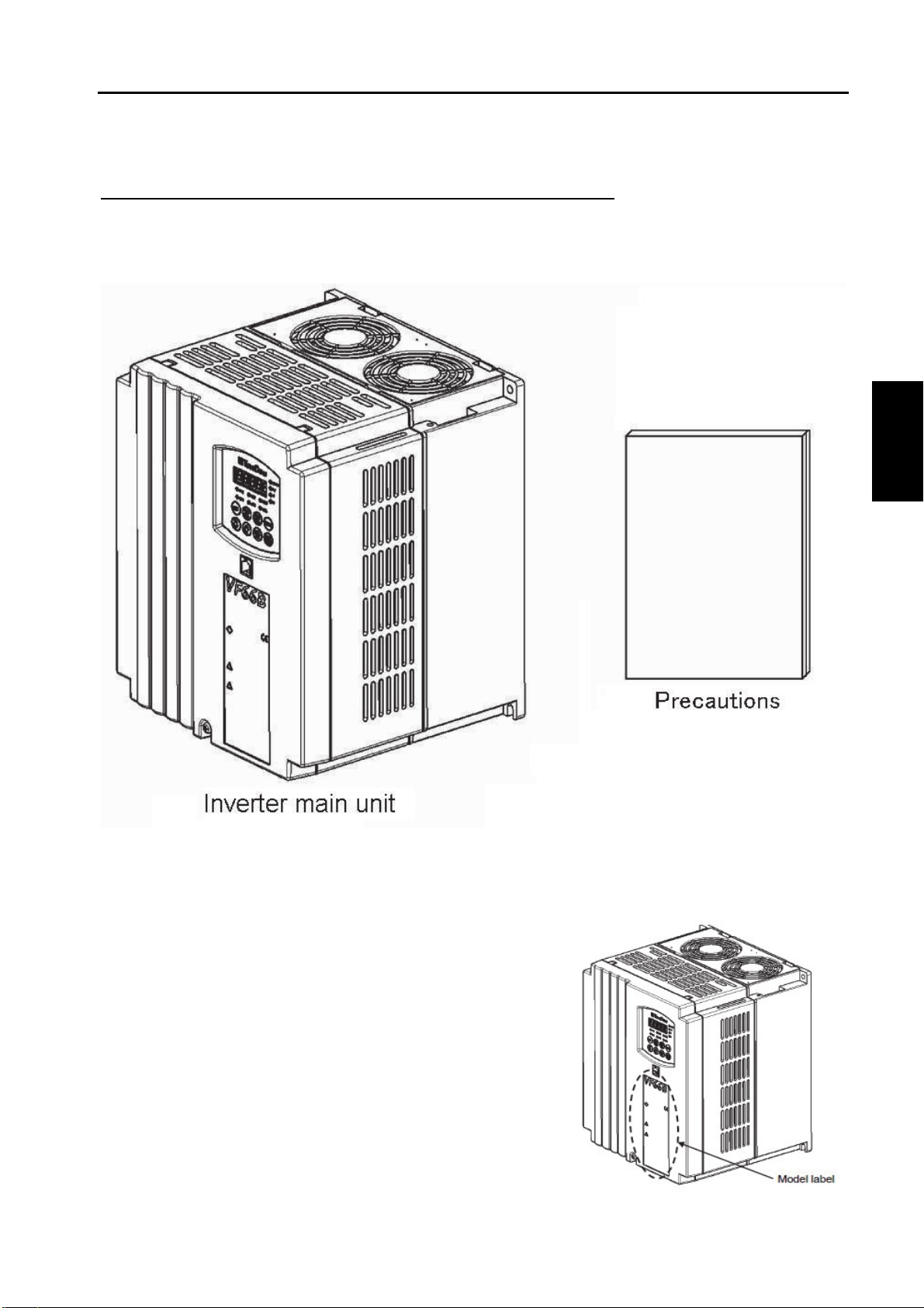
(1) Check that the package contains the inverter main unit and the Precautions.
(2) Check that the specifications, accessories, spares, and options are delivered as you order.
The label on the surface of the cover mentions the inverter-type.
Chapter 1 Checking and Inspecting Package
-9-

Safety notice
To use the inverter correctly, read this manual completely.
Our inverter is not designed and produced for the purpose of being used for a device or system under a
situation where human life may be threatened.
Do not use this inverter for special purposes such as riding, medical, aerospace, nuclear power control, and
a submarine repeater or system.
This inverter is produced under the strict quality control. However, when it is applied to an important facility
where its failure might threaten human life or cause expected serious losses, you should install any safety
devices to prevent serious accidents.
When using it for load other than a three-phase alternating current motor, consult with us.
This inverter requires electrical work. Electrical engineering technicians should do it.
Chapter 1
Example of the model label on the surface of the
cover
(3) Check the product for damages and loose or removed screws during transportation.
Chapter 1 Checking and Inspecting Package
-10 -

Chapter 2
Chapter 2 Product Overview
2.1 Features
■Provide three types of control methods to support various applications
The inverter can drive the induction motor and the Interior Permanent Magnetic Synchronous Motor (ED
motor) to support various applications.
・V/f control
Applications for controlling the general induction motor at variable speed
・Vector control without sensor (induction motor, ED motor)
Applications for requiring higher torque or more accurate speed control than V/f control
・Vector control with sensor (induction motor, ED motor)
Applications for requiring higher torque and high-accuracy speed control
■Standard feature of Autotuning
The inverter provides an Autotuning function where the inverter itself measures motor parameters such as
motor resistance and inductance and also automatically sets parameters.
It can be optimally operated with control methods of [V/f control], [Induction motor vector control], and [ED
motor vector control].
■Simple mode in which parameters can be easily set
The "simple mode," in which the display of parameters is minimized, enables you to prevent incorrect settings.
You can check operations promptly when introducing the inverter.
■Operation possible in two control modes
You can set two types of control methods and motors.
To switch two modes (control methods or motors), you only have to set control method or motor parameters
and then input external signals to the inverter.
■Reduced maintenance cost
Long-life parts are used for components which require replacement.
・Main circuit capacitor: About ten years (life expectancy in design)
・Cooling fan: About five years (life expectancy in design)
For 2.2 to 7.5 kW (200 V/400 V class), you can easily replace the cooling fan without mounting screws.
With a cumulative operation timer, you are automatically notified when to replace components (alarm function).
■Reduced running cost
The ED motor operated with high efficiency enables you to save energy. For the motor with larger volume and
longer use, you can reduce more running cost.
■Support for design and adjustment tool on personal computer
It provides a personal computer tool <VF66 series PC Tool> as an option to offer powerful support from
adjustment at the introduction of the inverter to maintenance.
Chapter 2 Product Overview
-11 -

[Induction motor vector control] and [ED motor vector control]
[Induction motor vector control]
The vector control enables you to control torque of the induction motor and to achieve high-speed and
high-accuracy speed control.
Since it develops higher torque at start, it can be used for line control such as a paper machine and film
processing as well as an extruder for rubber, plastic, and metal, a centrifuge, and a mixer. Also, since it has
a wider constant output (power constant) area, it can be applied to a winder and can be used under a poor
working environment with the speed control without sensor.
[ED motor vector control]
The vector control enables you to control torque of the ED motor and to achieve high-speed and high-
accuracy speed control.
When compared with the [induction motor vector control], this is optimal for the extruder for rubber, plastic,
and metal which requires continuous operation for energy saving.
Chapter 2
Chapter 2 Product Overview
-12 -

Chapter 2
2.2 Configuration
■Inverter main unit
・Front cover
This is a front cover of the inverter. For how to remove it, refer to {3.2.1 How to Open Front Cover}.
・Cooling fan
This is a fan motor for cooling. For how to replace it, refer to {7.3 How to Replace Cooling Fan}.
・Console
It is used for operation from the inverter main unit.
It consists of a seven-segment display, a unit LED, a status display LED, and operation keys.
For details, refer to {4.1.1 Explanation of Display and Operation Keys on Console}.
Chapter 2 Product Overview
-13 -
Chapter 2
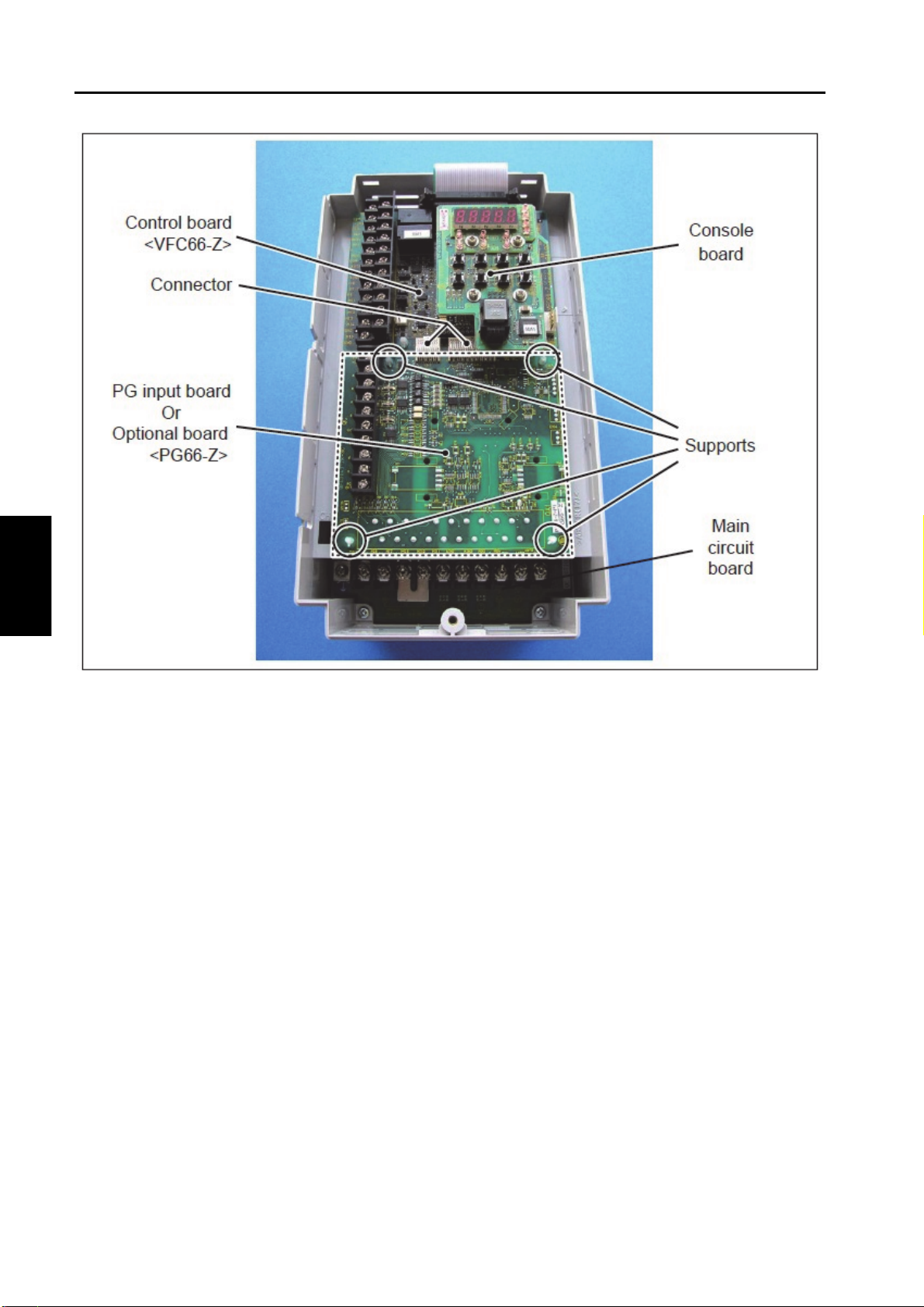
■Board
・Main circuit board <MAC66> (for 2.2 to 7.5 kW only)
This is a main circuit part of the inverter. A terminal block is located in the lower part of it.
For details of wiring, refer to {3.3.1 How to Connect Inverter Terminals} and {3.5 Notes for Wiring and
Electrical Wire Size}. For details of the terminal block, refer to {3.4 Terminal Specifications}.
・Control board <VFC66-Z>
This is a control part of the inverter. A terminal block is located on the left side.
For details of wiring, refer to {3.3.1 How to Connect Inverter Terminals} and {3.5.4 Electrical Wire Size on
Control Board and PG Input Board}. For details of the terminal block, refer to {3.4 Terminal Specifications}.
For how to replace the control board <VFC66-Z>, refer to {8.2 How to Replace Control Board}.
・Console board <SET66-Z>
This is a console part of the inverter. It has switches for the LED and the operation keys.
・PG input board <PG66-Z> or various optional boards
<PG66-Z> is used to connect a speed sensor (PG). A terminal block is located on the left side.
Optional boards are used to add external input/output and communication functions.
Chapter 2 Product Overview
-14 -

Chapter 3
Overvoltage category
Overvoltage
category Equipment Equipment overview
I Secondary circuit Equipment connecting to a circuit where any measures are taken to limit
transient overvoltage to a lower level. It includes a protected electronic
circuit.
II Home electrical
appliance and
office machine
Equipment consuming energy supplied from a fixed wiring facility.
III Electrical facility Equipment in the fixed wiring facility which especially requires reliability
and effectiveness.
IV Power receiving Equipment used for a service entrance.
Pollution degree
Pollution
degree Overview Specific example
1 There is no pollution, or only dry and non-conductive pollution
occurs. This type of pollution has no effect.
Clean room and others
2 Typically, only non-conductive pollution occurs. However, when a
PDS (Power Drive System) is not running, temporary conductivity
can be expected due to condensation.
Electrical equipment in
an office and the control
panel, and others
3 Conductive pollution, or dry and non-conductive pollution resulting in
conductivity due to expected condensation occurs.
In a general factory and
others
4 Pollution causes continuous conductivity due to conductive dust,
rain, and snow.
Outdoor and others
Chapter 3 How to Install and Connect Inverter
3.1 Surrounding Environment and How to Install It
3.1.1 Installation Environment
Install the inverter in an environment below the overvoltage category III and below the pollution degree 2
defined by the IEC60664-1.
3.1.2 How to Install Inverter
■Requirements of where to install the inverter
Installation conditions of the inverter will greatly affect its life and reliability. Avoid installing it in the places
listed below. Use it under the environmental conditions described in {Chapter 9 Standard Specifications}.
(1) In a humid and dusty area or a place where water or oil drips, the insulation of circuits is deteriorated,
which may reduce the life of parts.
(2) Too high ambient temperature will cause the life of the main circuit capacitor or the cooling fan to be
reduced.
(3) In a place containing corrosive gas, connectors may have a loose connection, electrical wires may be
disconnected, and parts may be damaged.
Chapter 3 How to Install and Connect Inverter
-15 -
Installation
●Install the inverter on non-inflammables such as metal.
Otherwise, a fire may occur.
●Do not put inflammables near the inverter.
Otherwise, a fire may occur.
●A model over 22 kW is considered as a heavy material. Don't lift it by yourself. Otherwise, you may be
injured.
●Do not hold the front cover when transporting the inverter.
It may fall, which may result in injury.
●Install the inverter in a place which can support its weight.
It may fall, which may result in injury.
●Do not install and operate the inverter which is damaged or does not have any parts.
Otherwise, you may be injured.
●Do not install the inverter in an atmosphere which contains plasticizer such as halogen and DOP
(phthalate ester).
Otherwise, it may be damaged.
How to install inverter
●Install it correctly.
Incorrect installation may result in a risk of electric shock or a fire.
Chapter 3
(4) In a place having many vibrations, connectors may have a loose connection, electrical wires may be
disconnected, and parts may be damaged.
(5) When using the inverter in a place where ambient temperature is below 0 ℃, use a heater, etc. to ensure
that it becomes 0 ℃or higher at the start of the inverter. After it starts, when the temperature becomes 0
℃or higher due to its heat generation, there is no problem.
■Mounting protective device
As a protective device when a short-circuit causes an accident, be sure to connect a fuse on the input side of
the inverter. Use a fuse described in {3.5.3 Electrical Wire Size of Main Circuit Wires}.
■Action after short-circuit
Dispose a short-circuited inverter in any circumstances without using it.
■Inverter installation requirements and heat radiation
To use the inverter, incorporate it into the control panel, etc. to meet the environmental conditions for
installation.
・Exhaust amount required for inverter loss and heat radiation
Inverter loss is represented as a ratio to the motor load capacity as follows:
2.2to37kW:5.0%,45to55kW:4%,75to90kW:3%,110to315kW:2.5%
For example, when the motor load is 3.7 kW, the loss is 3.7 kW x 5.0 % = 185 W.
When heat generated from the inverter is forcibly exhausted outward by an exhaust fan installed on the
control panel, necessary exhaust amount can be calculated in the following formula:
Q=q/{ρ・C・(To-Ta)}
Chapter 3 How to Install and Connect Inverter
-16 -

Heat radiation and exhaust
・The DCL becomes hot. It may exceed 100 ℃. Provide enough space to keep away from other devices.
・Make sure that heat generated from the inverter and the DCL is exhausted outward from the control
panel. Note that exhaust from the inverter should not circulate in the control panel.
・When using a dynamic braking (DB) optional unit <VFDB2009>, install a dynamic braking (DB) resistor
outside from the control panel as much as possible.
・Avoid using the inverter in a seriously worse environment.
Chapter 3
Where
Q: Exhaust flow (m3/s)
q: Amount of heat generated from the inverter (kW)
ρ: Density (1.057 to 1.251 kg/ m3)
C: Specific heat (1.0 kJ/kg・℃)
To: Exhaust fan exit temperature (℃)
Ta: Control panel inlet temperature (℃)
When ambient temperature on the control panel is 40 ℃, to ensure that exhaust temperature is below 50
℃, a difference between intake and exhaust should be 10 ℃.
To exhaust a loss of 1 kW, an exhaust ability of about 0.1 m3/s is required.
・Installation orientation and intake/exhaust direction
Install the inverter vertically with a logo mark "VF66B" facing up. When it is installed sideways, ventilation
is prevented, which may increase temperature. You should sufficiently consider a path of intake and
exhaust.
The cooling fan built in the inverter sucks air from the bottom and exhausts it to the top. To prevent a wiring
duct, etc. from blocking up the vent, keep enough space.
・Keeping cooling space
To install the inverter and an optional direct-current reactor (DCL), keep cooling space.
When heat generation devices exist in the surrounding environment, place them so that they do not affect
cooling of the inverter and others.
The operating temperatures of the inverter are 0 to 50 ℃. To install it in the control panel, perform
ventilation to ensure that the temperature in the board is below 50 ℃. High ambient temperature will
decrease reliability.
The figure below shows cooling space required for models below 7.5 kW. For models over 11 kW, keep
the size twice as much as the dimensions described in the figure.
Chapter 3 How to Install and Connect Inverter
-17 -

Opening and closing front cover
●Be sure to turn off the inverter when opening and closing the front cover.
Otherwise, it may result in a risk of electric shock.
1. Use the Phillips screwdriver (M4) to loosen a mounting
screw on the front cover.
・You do not have to
r
emove the sc
r
ew.
2. Lift the cover in the direction of the arrow (
A
)tothe
position shown in the figure, using two claws on the top of
the front cover as supporting points.
3. Push the front cover in the direction of the arrow (B) and
then remove the two claws on the front cover from the
inverter main unit.
Chapter 3
3.2 How to Open and Close Front Cover
3.2.1 How to Open Front Cover
To work inside the inverter (such as connecting or wiring terminals, and maintenance/inspection), follow the
steps below to open the front cover.
■For models below 7.5 kW consisting of a resin chassis and front cover
Chapter 3 How to Install and Connect Inverter
-18 -
Other manuals for VF66B
3
Table of contents
Other TOYODenki Inverter manuals


