Toyota Fortuner UH9000S User manual
UHF CB Transceiver
UH9000S / UH9060S / UH9080S
Fitting Instructions
Fortuner
Fitting Kit Part Number: UNIFK001
Page 2 of 14
Fitting Instructions
UH9000S / UH9060S / UH9080S
UHF CB Transceiver
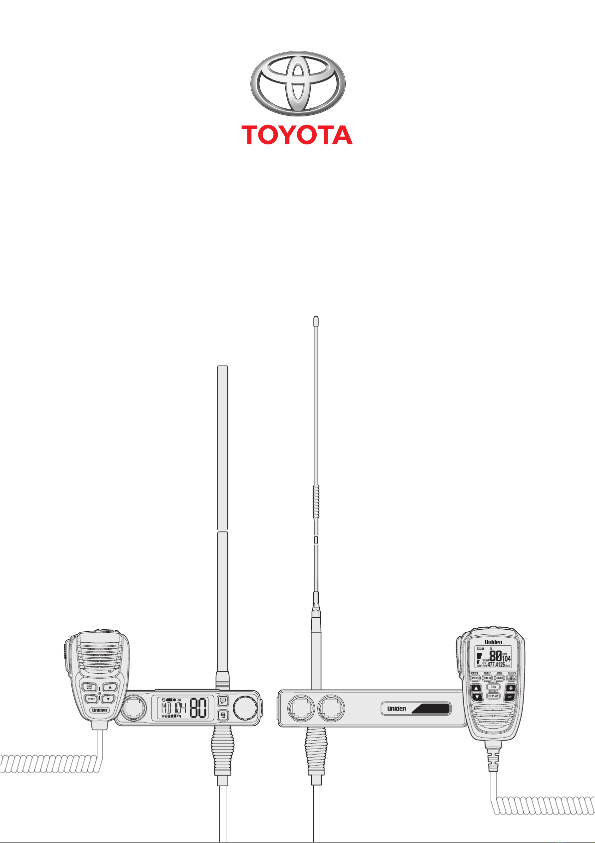
Front
Antenna
Connector
Speaker
Microphone
UH9000S
Rear
Earth
A
ccessory
Power
+
Fuse
Power
Lead Patch
Harness
Antenna
Connector
Extension
Cable
(Optional)
UH9060S / UH9080S
Earth
A
ccessory
Power
+
Fuse
Remote LCD
Speaker
Microphone
Rear
UHF CB Transceiver
Front
Power
Lead Patch
Harness
Fitting Instructions
UH9000S / UH9060S / UH9080S
Page 3 of 14
WARNING
This vehicle is equipped with Supplemental Restraint System (SRS) airbags and seatbelt pretensioners.
Before starting work, wait at least 90 seconds after the ignition switch is turned off and the negative (-) battery terminal
cable is disconnected.
SRS parts are equipped with a backup power source. If work is started within 90 seconds of turning the ignition switch off
and disconnecting the negative (-) battery terminal cable, SRS parts may deploy possibly causing serious injuries.
WARNING
Do not install any parts in a location that may interfere with the operation and deployment of the SRS airbags or seatbelt
pretensioners, including driver, front passenger and knee SRS airbags if tted. Doing so may result in serious injury or
death.
PREPARATION
• Follow all standard workshop and occupational health and safety practices during the installation process.
• Check and note any existing marks or damage to the vehicle.
• Before starting the installation thoroughly read through these installation instructions then follow the tting sequence as described.
• Check that the UHF CB transceiver kit is complete.
• Take all possible precautions to avoid damaging the vehicle’s interior and exterior during the installation. Use protective tape on
parts and tools where necessary.
• To avoid damage to the wiring harness and antenna cable, avoid contact with sharp edges. Cable tie securely every 200 mm.
• Ensure all removed parts are re-tted correctly.
SPECIAL TOOLS
• Trim removal tools
• Protective tape
• Lead wire
PARTS LIST - UHF CB TRANSCEIVER KITS
Model UHF CB Transceiver Kit Fitting Kit Part Number
FORTUNER
UH9000S
UNIFK001UH9060S
UH9080S
PARTS LIST - ANTENNA
Model Antenna Part Number Description
FORTUNER
AT970BKTWIN Antenna Dual Whip Black
AT970WTWIN Antenna Dual Whip White
AT970BK Antenna 1200mm Black
AT970W Antenna 1200mm White
AT890BK Antenna 1000mm Black
AT890W Antenna 1000mm White
AT880TWIN Antenna Dual Whip Stainless Steel
Fitting Instructions
UH9000S / UH9060S / UH9080S
Page 4 of 14
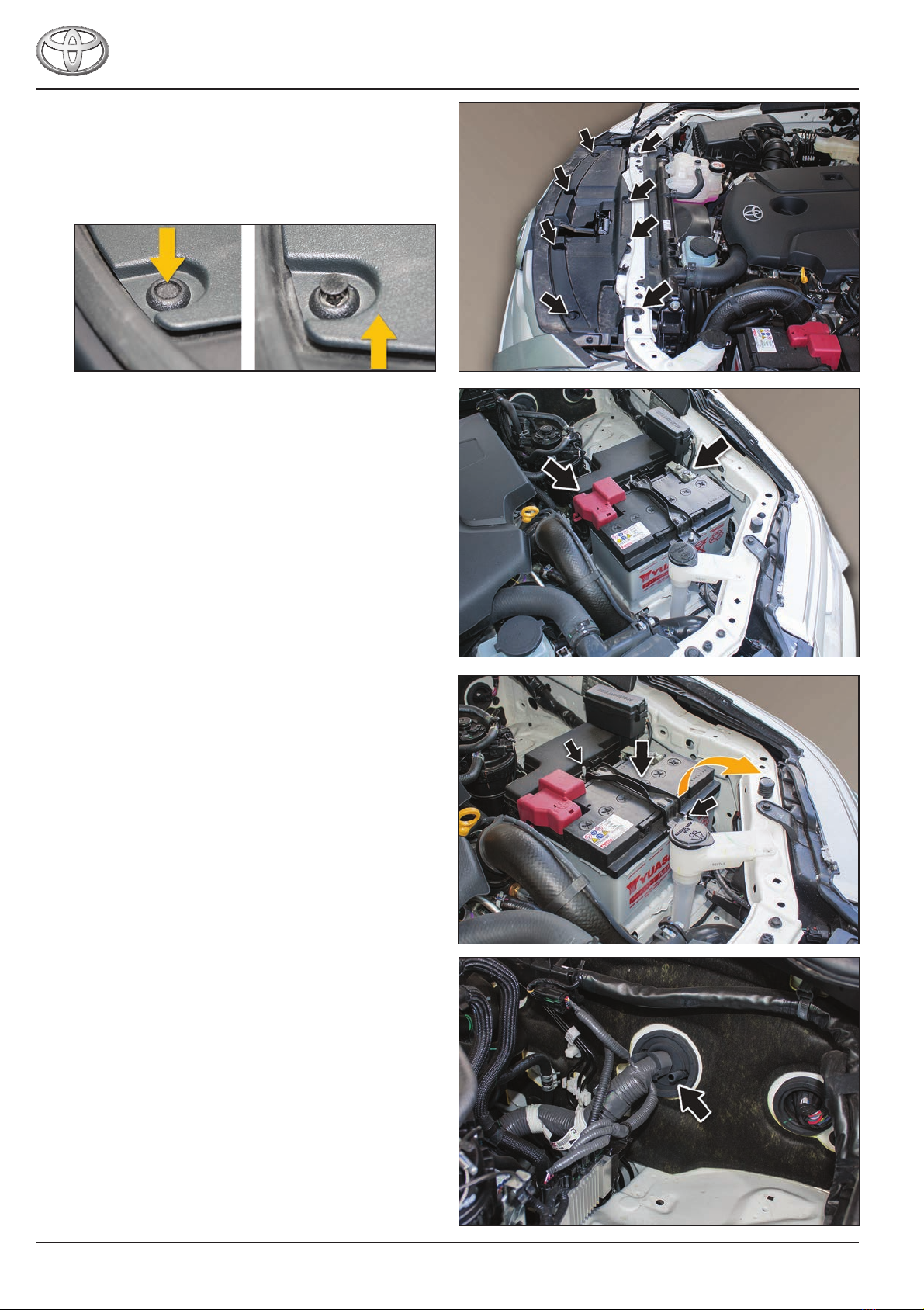
REMOVAL
Removal - Engine Bay
1. Open the bonnet.
2. Remove the radiator shroud (8 scrivets).
Push in the centre of the scrivets and pull up the shroud to
remove. Take care to retain all scrivets.
3. Disconnect the (-) negative battery terminal cable.
4. Disconnect the positive (+) terminal cable.
5. Remove the battery retaining bracket and hook.
6. Remove the battery and store safely.
7. Cut the outer tang off the rewall grommet where
indicated.
Note: Refer to the Alternate antenna cable entry point
on page 8 if both grommet entry points are being
used.
Fitting Instructions
UH9000S / UH9060S / UH9080S
Page 5 of 14
Removal - Interior
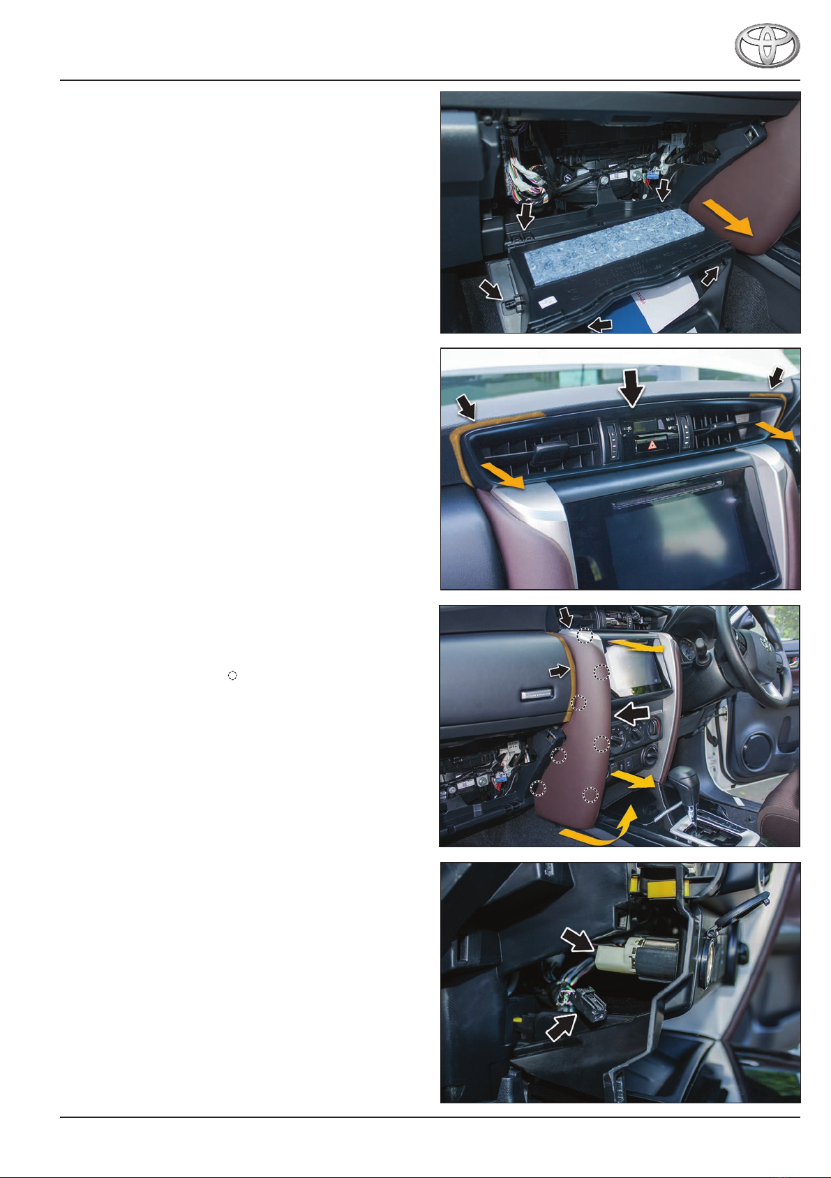
1. Remove the glovebox.
Open the glovebox and remove the (2) stopper pins by
rotating 90º and pulling out.
2. Unclip the damper rod.
3. Open the glovebox fully and pull away from the lower
retaining clips.
4. Place protective tape around the instrument panel garnish
as indicated.
5. Release the instrument panel register bezel garnish.
Carefully pull out slightly from the positions indicated to
release the passenger side centre instrument panel
garnish upper retaining tabs (it is not necessary to remove
fully).
6. Place protective tape around the instrument panel as
indicated.
7. Firmly release the bottom of the passenger’s side centre
instrument panel garnish sub-assembly, then pull straight
back to remove.(7 clips [ ]) .
8. Disconnect the power socket black connector.
Fitting Instructions
UH9000S / UH9060S / UH9080S
Page 6 of 14
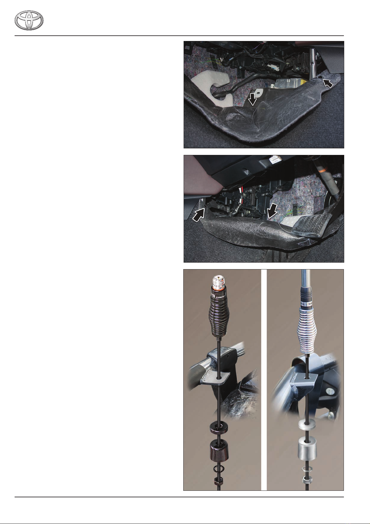
9. Remove the (1) xmas tree clip and fold down the
passenger’s side footwell carpet.
10. Remove the (1) xmas tree clip and fold down the driver’s
side footwell carpet.
INSTALLATION
Antenna
1. Remove the sleeve, spacer washer, lock washer and nut
from the antenna.
2. Pass the antenna cable through the antenna mounting
hole.
3. Secure the antenna to the mount using the sleeve, spacer
washer, lock washer and nut. Tighten securely.
Fitting Instructions
UH9000S / UH9060S / UH9080S
Page 7 of 14
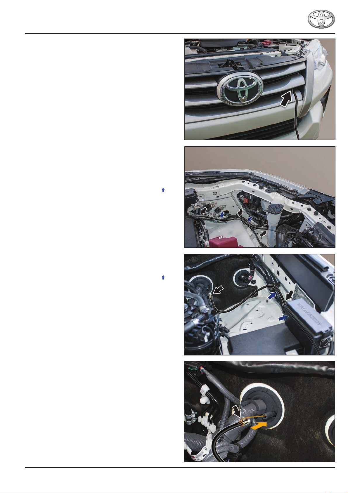
Antenna Cable
1. Pass the antenna cable through the radiator grille opening
in the location as shown.
2. Route the antenna cable through the radiator support
panel to the existing wiring harness behind the left hand
side headlight assembly.
3. Follow the existing wiring harness beside the battery tray,
below the accessory fuse box towards the rewall.
4. At the completion of the installation, cable tie the antenna
cable to the existing wiring harness where indicated [ ].
5. Follow the existing wiring harness and route to the rewall
grommet as shown.
6. At the completion of the installation, cable tie the antenna
cable to the existing wiring harness where indicated [ ].
7. Pass a lead wire through the cut rewall grommet opening
to the passenger’s side footwell.
Attach the antenna cable to the lead wire.
Note: Refer to the next step if both grommet entry points
are being used.

Fitting Instructions
UH9000S / UH9060S / UH9080S
Page 8 of 14
Alternate antenna cable entry point
7. Remove the grommet from rewall:
a. Drill a 5 mm hole through the centre.
b. Ret the grommet to the rewall opening.
c. Pass a lead wire through the cut rewall grommet
opening to the passenger’s side footwell.
d. Attach the antenna cable to the lead wire.
8. Carefully pull the lead wire and antenna cable through
from the passenger’s side footwell.
IMPORTANT
Use silicon spray to allow the antenna cable to pass
through the grommet more easily.
At the completion of the installation process seal the
antenna cable grommet entry point with an automotive
grade sealant and secure with a cable tie.
UH9000S
9. Disconnect the lead wire and route the antenna cable
below the footwell carpet line, behind the centre console
towards the driver’s side footwell.
10. Pull the antenna cable through to the driver’s footwell.

Fitting Instructions
UH9000S / UH9060S / UH9080S
Page 9 of 14
UH9060S / UH9080S
9. Disconnect the lead wire and pull the antenna cable
through to the passenger’s side footwell.
Power Lead Patch Harness - UH9000S
1. Route the power lead patch harness from the driver’s side
footwell, through the centre console to the rear of the
power socket located in the centre console.
2. Disconnect the power socket connector and dehouse the
(2) connector pins from the rear power socket connector
[1].
3. House the (2) removed pins in the free power lead patch
harness connector [2].
4. House the (2) free power lead patch harness pins into the
existing power socket connector [3].
5. Connect the existing power socket connector to the power
socket [4].
IMPORTANT
6. Refer to the following diagram for wiring details.
Fitting Instructions
UH9000S / UH9060S / UH9080S
Page 10 of 14
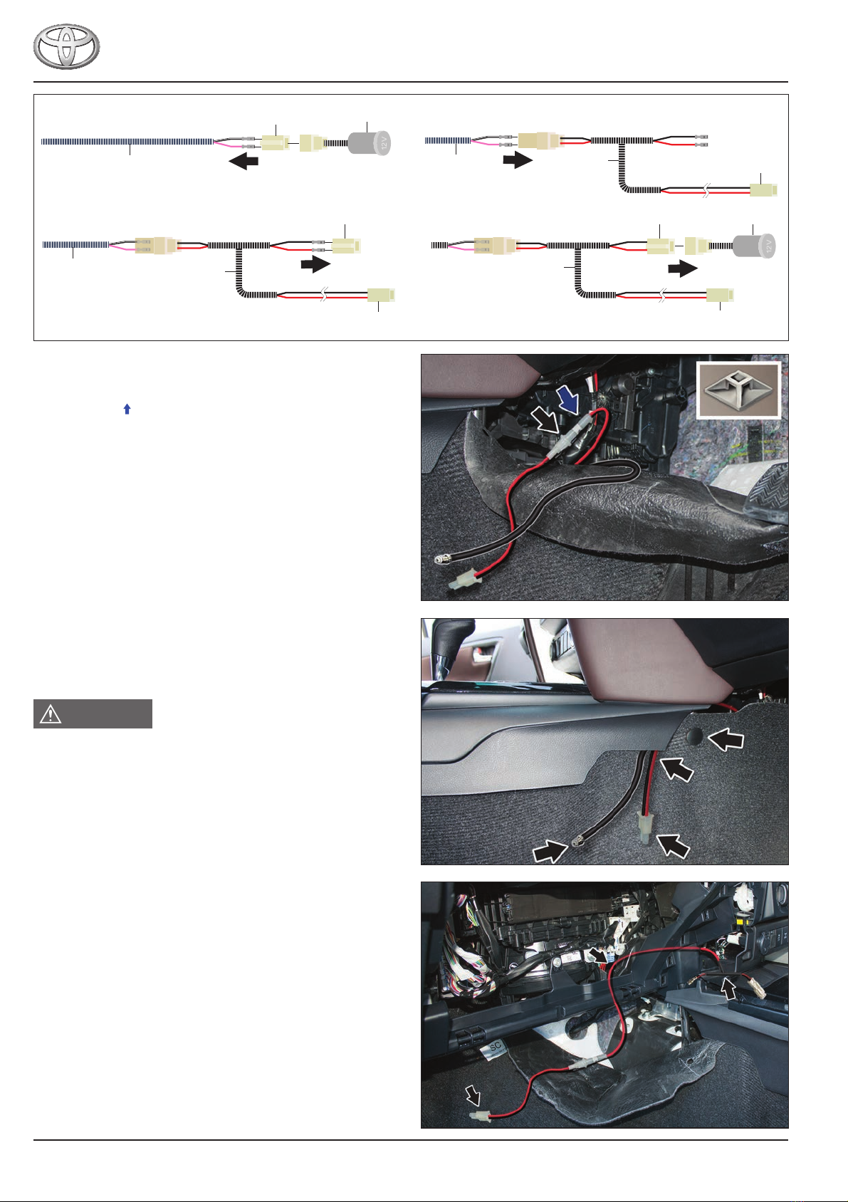
7. Position the power lead patch harness fuse holder/s neatly
behind the driver’s side instrument panel nish cushion
and carpet.
Cable tie [ ] using self-adhesive cable tie mounting blocks
where necessary to avoid fouling and rattling.
8. Position the UHF CB transceiver power lead patch harness
and antenna cable trailing below the centre console panel.
Ret the driver’s side footwell carpet and secure with
existing xmas tree clip.
WARNING
Ensure the driver’s footwell carpet and oormat (if tted)
are repositioned correctly to avoid fouling with the foot
pedals operation.
Power Lead Patch Harness - UH9060S / UH9080S
1. Route the power lead patch harness from the passenger’s
side footwell through the centre console to the rear of the
power socket located in the centre console.
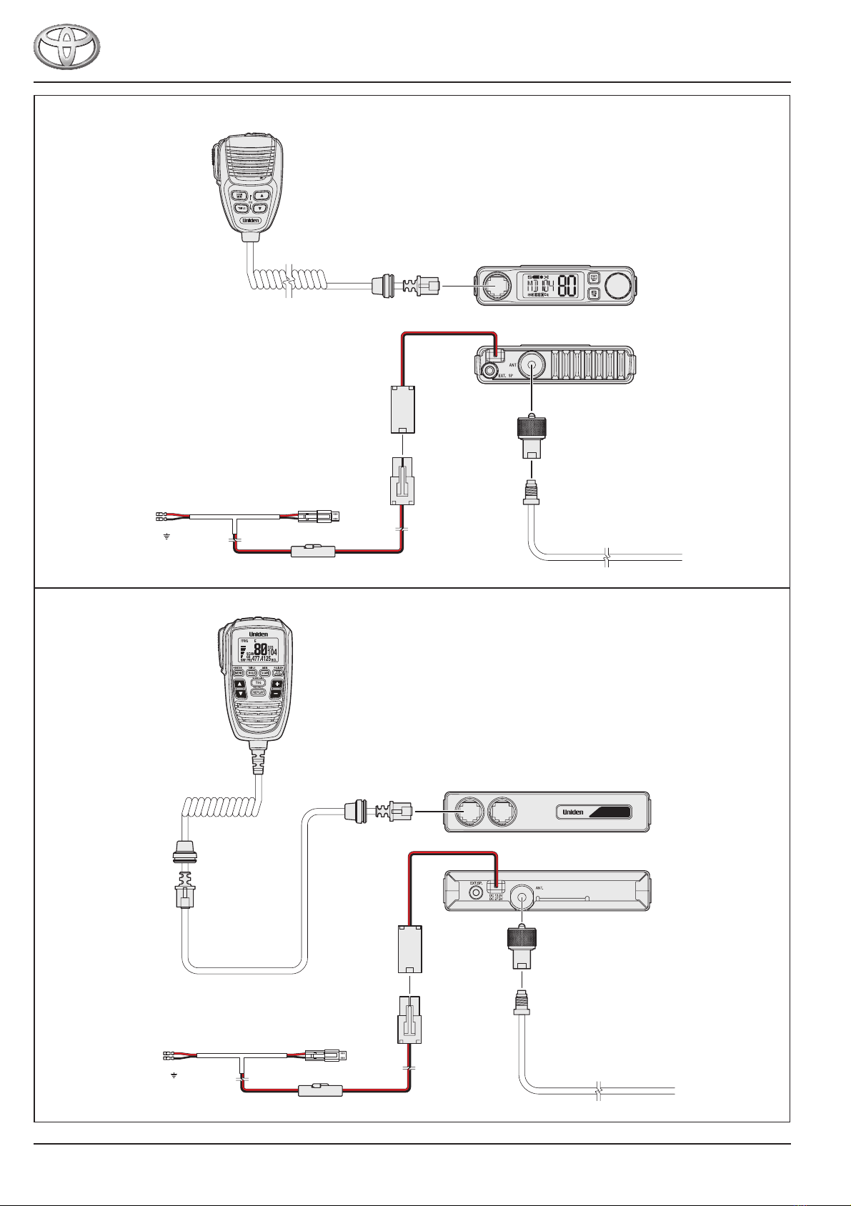
Fortuner
1
Power
socket
Existing vehicle
harness
Existing vehicle power
socket connector
Existing vehicle power
socket connector Power
socket
4
To UHF CB
transceiver
Power lead
patch harness
Existing vehicle power
socket connector
To UHF CB
transceiver
3
Existing vehicle
harness Power lead
patch harness
2
Existing vehicle
harness Power lead
patch harness To UHF CB
transceiver
1
2
1
2
1
2
Other manuals for Fortuner UH9000S
1
This manual suits for next models
2
Table of contents
Other Toyota Transceiver manuals


