TP-Link VIGI SP9030 V1 User manual

Installation Guide
Intelligent Solar Power Supply System

Contents
Chapter 1 Appearance——————————— 3
Chapter 2 Installation ——————————— 6
2.1 Package Contents ...............................................6
2.2 Safety Precautions ..............................................6
2.3 Installation...............................................................7
Chapter 3 Conguration —————————— 12
Appendix FAQ——————————————— 13

3
Chapter 1 Appearance
The TP-Link VIGI intelligent solar power supply system consists of three
parts: horizontal mount, solar panel, and vertical mount.
The TP-Link VIGI intelligent solar power supply system can provide
stable and reliable voltage output for various electronic devices (such as
security surveillance cameras, outdoor wireless APs, wireless bridges,
4G routers, etc.). It is widely used in rural areas, scenic spots, orchards,
reservoirs, factories, mines, forests, etc., where power supply and
networking are hard to provide.
The figures in this guide are for demonstration purposes only. Your
device may differ in appearance from what is depicted.
■Horizontal Mount (containing Controller and Modular Battery)
The horizontal mount (containing controller and modular battery) is
shown as the following figure.
Load Interface
Load Interface #1: 9-12.6VDC
Load Interface #2: 9-12.6VDC
Load Interface #3: 12VDC RJ45 Network interface for
connecting network devices
such as 4G routers and bridges
Four-pin female
connector for
connecting a
solar panel
Controller LED

4
• Controller LED
LED Indication
SYS
On: The system is working and the load is enabled.
Flashing: The system is working and the load is disabled.
Off: The system is not working.
LAN
On: The RJ45 interface is connected.
Flashing: Data is being transferred.
Off: The RJ45 interface is not connected.
PV On: PV panels are connected and have voltage.
Off: PV panels have no voltage.
BAT
On: Battery power is higher than 20%.
Slow Flashing: Battery power is lower than 20%.
Quick Flashing: Intelligent auxiliary heating.
Off: Battery is abnormal.
• Specifications
Items VIGI SP6020 VIGI SP6030 VIGI SP9030
Size 622×613×690mm 622×613×998mm
Weight 14kg 15kg 17.5kg
Material Galvanized Sheet, Polycarbonate Resin
Battery Capacity 20.8AH 31.2AH
Battery Working
Voltage 9~12.6V
Solar Panel 60W/18V 90W/18V
Output 12VDC 2A max per output port
Operating
Temperature -30~60°C
■Solar Panel
The solar panel is shown as the following figure.

5
• Specifications
Items VIGI SP6020/VIGI SP6030 VIGI SP9030
Size 690mm×516mm×30mm 998mm×516mm×30mm
Output Power/
Voltage 60W/18V 90W/18V
Material Monocrystalline Silicon
■Vertical Mount
The mount is shown as the following figure.
Vertical
Mount
PTZ Camera
Connector
Items VIGI SP6020/VIGI SP6030/VIGI SP9030
Size 191mm×40mm×82mm
Operating Temperature -30~60°C
Operating Environment Outdoor

6
Chapter 2 Installation
2.1 Package Contents
Make sure that the package contains the following items. Please contact
your distributor, if any of the listed items are damaged or missing.
The figures are for demonstration only. The actual items may differ in
appearance and quantity from what is depicted.
Horizontal Mount Vertical Mount
U-shaped Screws (2)
Installation Guide
Mounting Screws (12 screws, 12 nuts, 12 at washers)
Solar Panel Screws (2) L-shaped Hex Screwdriver
Solar Panel
PTZ Camera Connector PTZ Camera Connector
Mounting Screws (12)
Waterproof Cable
Attachments
2.2 Safety Precautions
• During installation, collision and knocking are strictly prohibited to avoid
damage.
• When placing the modular battery, make sure that the solar panel is
facing upwards and placed horizontally. Uneven ground may scratch or
damage the solar panel.
• Make sure there are no fixed obstructions. If installed around buildings
or trees, it is necessary to ensure the installation height of the battery
panel is higher than the obstacle.

7
• All modular battery load interfaces should take strict waterproof
measures to avoid short circuit, leakage, and other problems.
2.3 Installation
Step 1. Determine the installation location
Choose a location where the solar panel receives the most sunlight
throughout the year. Position the solar panel south-facing in the Northern
Hemisphere or north-facing in the Southern Hemisphere.
Step 2. Install the horizontal mount
Fix the horizontal mount to the vertical pole with U-shaped screws.
Tip: Determine the direction according to a compass or mobile phone
compass software, and adjust the orientation of the bracket to obtain the
maximum solar energy.
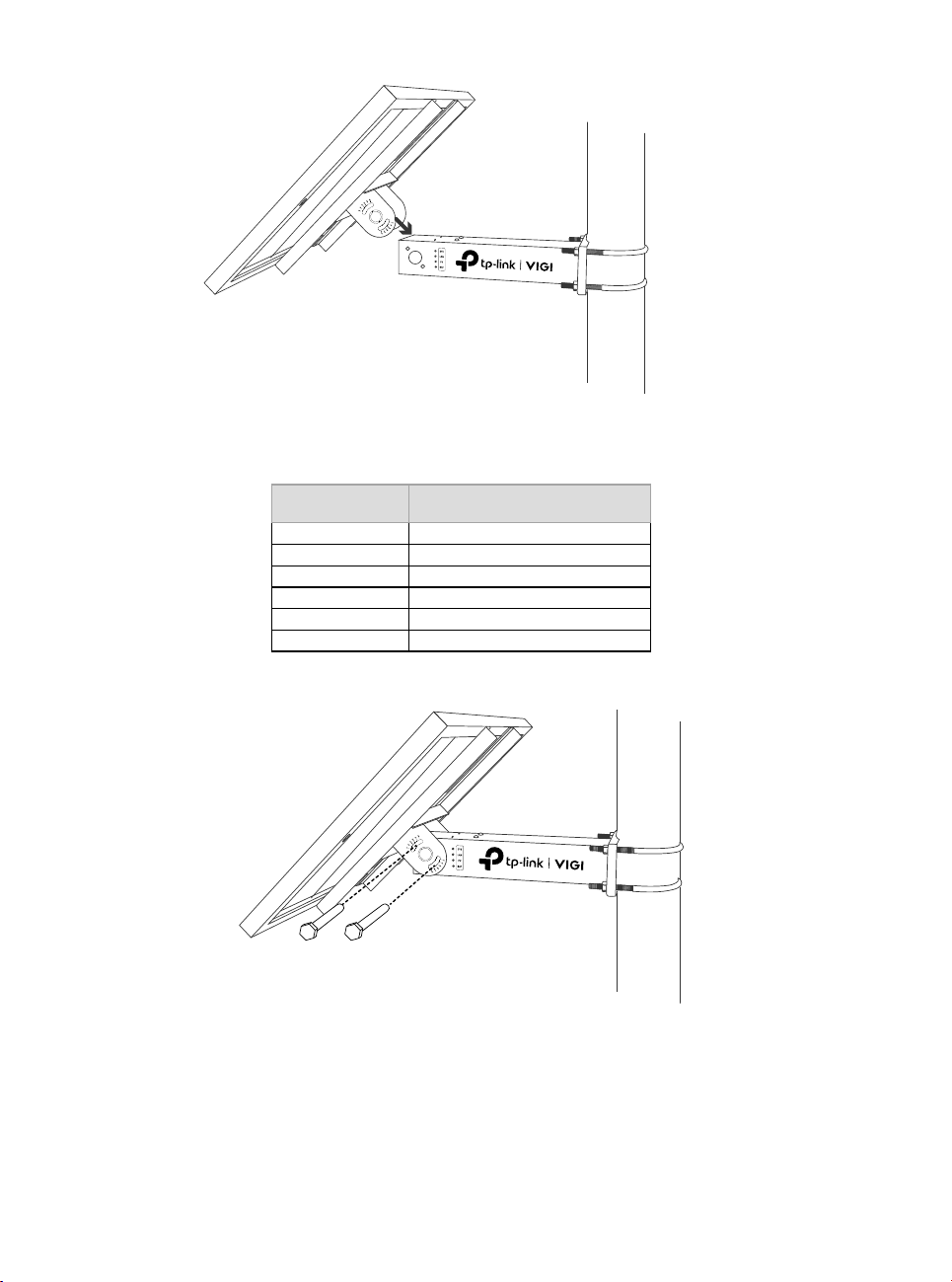
Step 3. Install the solar panel
1. Fix the solar panel on the mount. Determine the installation inclination
according to the location (the inclination can be determined according
to the latitude of the location).
8
Recommended solar panel inclination angles (the following inclination
angles correspond to the holes on the mount):
Latitude Range Recommended Inclination
0-5° 5°
5-15°15°
15-25°25°
25-35°35°
35-45°45°
>45° 55°
2. Install the solar panel using the solar panel matching screws.
Step 4. Install the vertical mount
1. Install the vertical mount to cross the horizontal mount.

9
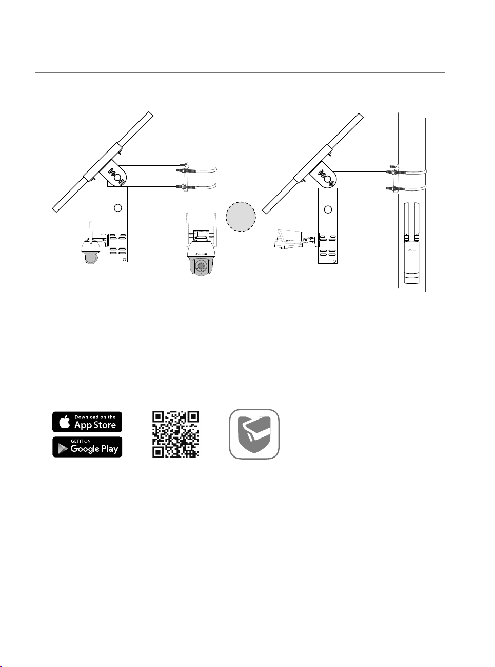
2. Install devices on the vertical mount. Different types of mounts have
varying access methods, and the corresponding type of bracket
should be selected for installation according to the actual situation of
the device.
The installation hole diagram of the load at the end of the vertical mount is as follows:

10
1 Install the PTZ camera connector
2 Install the PTZ camera
Note: If the product is used in a windy area, it is recommended to tie VIGI 5-Series
cameras directly to the pole to reduce the impact of strong wind on the image quality
of the camera.

11
3. After connecting the camera to the load interface, wrap the
connection with over two layers of waterproof tape (not included), as
shown below.
Note: When using waterproof tape, wrap the rst layer, then cut. Apply a second layer,
ensuring no gaps between the connection and tape for secure waterproong.
Step 5. Install Waterproof Cable Attachments
Install the waterproof cable attachments for the network interface if
needed.
Note: Make sure each part is securely attached and the waterproof rings are ush to
keep out water.
Fix Nut Waterproof
Ring
O-ring Network
Interface
Waterproof
Jacket
1. Route the network cable through the following components in order:
fix nut, waterproof ring, and then the waterproof jacket.
2. Fix the O-ring to the network interface of the solar panel and connect
the network cables.
3. Attach the network interface with the waterproof jacket, then twist to
lock.
4. Insert the waterproof ring into the waterproof jacket. Rotate the fix nut
to secure it to the waterproof jacket.
12
Chapter 3 Configuration
Here is a typical network topology for the solar panel.
VIGI C540-4G
4G Network Camera Network Devices
(such as wireless access
points, network bridges, etc.)
Or
Step 1. Connect the RJ45 network interface of the solar panel to the
network devices (such as access points, bridges, and 4G cameras).
Step 2. Follow the instructions to finish Quick Setup.
1. Download and install the latest TP-Link VIGI app.
or
2. Open the app and log in with your TP-Link ID. If you don’t have an
account, sign up first.
3. Tap the + button on the top right and follow the app instructions to add
the solar panel.
Step 3. Done.
The solar panel system is added to your network and can provide power
to your devices. You can control and manage the solar panel system via
the VIGI app remotely.

13
Appendix FAQ
Q1. The controller LED status is abnormal.
• SYS LED is off: It may be out of power or the system board is damaged.
• LAN LED is off: There is no connection. Check whether the RJ45 interface is firmly
connected to the network device.
• PV LED is off: The PV panel is not connected or works abnormally and cannot
generate electricity.
• BAT LED is off: The battery is working abnormally.
Q2. Short system runtime and short monitoring time
• The battery board is disconnected: Check whether the solar panel interface is
connected well, and ensure that the solar panel is in working condition.
• The solar panel is blocked: Check whether the solar panel is blocked by foreign
objects or the front of the solar panel is dirty, which will affect its power generation
efficiency.
• Inefficient equipment system: Confirm the power consumption of the equipment.
If the power consumption is large, it is recommended to replace it with a solar-
powered product with a higher specification.

14
Safety Information
• Do not attempt to disassemble, repair, or modify the device.
• Do not use damaged charger or USB cable to charge the device.
• Do not use any other chargers than those recommended.
• Adapter shall be installed near the equipment and shall be easily accessible.
• Use only power supplies which are provided by manufacturer and in the original packing of
this product. If you have any questions, please don't hesitate to contact us.
• Avoid disposal of a battery into fire or a hot oven, or mechanically crushing or cutting of a
battery, that can result in an explosion.
• Place the device with its bottom surface downward. Install it at stable places, and prevent it
from falling.
• Keep the device away from fire or hot environments. DO NOT immerse in water or any other
liquid.
This equipment is not suitable for use in locations where children are likely to be present.
*Some devices may be incompatible, such as wireless mouse.
Please read and follow the above safety information when operating the device. We cannot
guarantee that no accidents or damage will occur due to improper use of the device. Please use
this product with care and operate at your own risk.
CAUTION!
Avoid replacement of a battery with an incorrect type that can defeat a safeguard.
Avoid disposal of a battery into fire or a hot oven, or mechanically crushing or cutting of a
battery, that can result in an explosion.
Do not leave a battery in an extremely high temperature surrounding environment that can
result in an explosion or the leakage of flammable liquid or gas.
Do not leave a battery subjected to extremely low air pressure that may result in an explosion
or the leakage of flammable liquid or gas.
EU Declaration of Conformity
TP-Link hereby declares that the device is in compliance with the essential requirements and
other relevant provisions of directives 2014/30/EU, 2014/35/EU, 2011/65/EU and (EU)2015/863.
The original EU Declaration of Conformity may be found at https://www.tp-link.com/en/support/
ce/
UK Declaration of Conformity
TP-Link hereby declares that the device is in compliance with the essential requirements and
other relevant provisions of the Electromagnetic Compatibility Regulations 2016 and Electrical
Equipment (Safety) Regulations 2016.
The original UK Declaration of Conformity may be found at https://www.tp-link.com/support/
ukca/


© 2023 TP-Link 7106510490 REV1.0.1
To ask questions, nd answers, and communicate with TP-Link users or engineers, please
visit https://community.tp-link.com to join the TP-Link Community.
For technical support, user guides and other information,
please visit https://www.tp-link.com/support, or simply scan the QR code.
Table of contents
Other TP-Link Power Supply manuals


Popular Power Supply manuals by other brands

jeri
jeri V4 user manual

Schumacher
Schumacher 00-99-000990-0809 owner's manual

Alternative Heating & Supplies
Alternative Heating & Supplies SUREFIRE 512 STOVE SENTRY instruction manual

Elenco Electronics
Elenco Electronics XP-15K Assembly and instruction manual

Ross
Ross DFR-8104A user manual

Roger
Roger PS15v24 user manual


