TPL TPL255 P-72 User manual

TPL ENERGY CO., LIMITED
FLAT 107, 25 INDESCON SQUARE, LONDON, UNITED KINGDOM
1
Installation Manual for TPL SOLAR PV Module
1. General Information
1.1 Overview
Thanks for choosing TPL ENERGY CO., LIMITED (TPL SOLAR) PV modules.
Please read this manual completely before installing TPL SOLAR module. This
module produces electricity when exposed to light. Follow all applicable electrical
safety precautions. Only qualified personnel should install or perform
maintenance work on this module. Do not handle modules when they are wet.
1.2 INTRODUCTIONS
TPL SOLAR modules come in various sizes to satisfy a full range of applications.
Each module is made of crystalline-silicon cells. To protect the cells from the
most severe-environmental conditions, modules are made of high transmission
rate and low iron tempered glass, anti-aging encapsulation material, and high
climate resistant and insulation back sheet by hot lamination, with anodized
Aluminum alloy frame and junction box.
Make sure the array of modules installed within the Maximum permitted system
voltage and the rating current and voltage of the sub-equipments such as
regulators and inverters. The maximum permitted system voltage (DC) of the
modules sold in Europe is 1000V
The assembly is to be mounted over a fire resistant roof covering rated for the
application. Before mounting the module, please consult your local building
department to determine approved roofing materials.
The modules are qualified for application class A: Hazardous voltage (IEC 61730:
higher than 50V DC; EN 61730: higher than 120V), hazardous power
applications (higher than 240W) where general contact access is anticipated
(Modules qualified for safety through EN IEC 61730-1 and -2 within this
application class are considered to meet the requirements for Safety Class II.
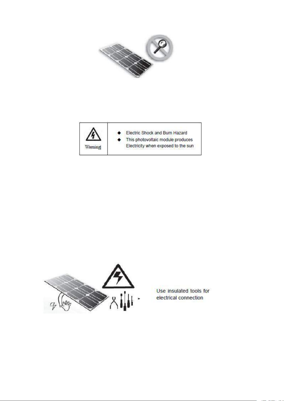
1.3 Warnings
PV modules generate DC electrical energy when exposed to sunlight or other
light sources. Active parts of module such as terminals can result in burns, sparks,
and lethal shock.
Artificially concentrated sunlight shall not be directed on the module or panel.
TPL ENERGY CO., LIMITED
FLAT 107, 25 INDESCON SQUARE, LONDON, UNITED KINGDOM
2
Front protective glass is utilized on module. Broken solar module glass is an
electrical safety hazard (may cause electric shock and fire). These modules
cannot be repaired and should be replaced immediately.
To reduce the risk of electrical shocks or burns, modules may be covered with
an opaque material during installation to avoid shocks or burns.
The installation work of the PV array can only be done under the protection of
sun-sheltering covers or sunshades and only qualified person can install or
perform maintenance work on this module.
Follow the battery manufacture’s recommendations if batteries are used with
module.
Do not use this module to replace or partly replace roofs and walls of living
buildings.
Do not install modules where flammable gas may be present.
Do not touch live terminals with bare hands. Use insulated tools for electrical
connections.
Do not remove any part or disassemble the module.
All instructions should be read and understood before attempting to install,
wire, operate and maintain the module.

TPL ENERGY CO., LIMITED
FLAT 107, 25 INDESCON SQUARE, LONDON, UNITED KINGDOM
3
Please do not lift up PV modules using the attached cables or the junction
box.
All PV systems must be earthed. If there is no special regulation, please follow
the National Electrical Code or other national code.
Under normal conditions, a photovoltaic module is likely to experience
conditions that produce more current and/or voltage than reported at standard test
conditions. Accordingly, the value of Isc and Voc marked on this module should be
multiplied by 1.25 when determining PV system component voltage ratings,
conductor current ratings, fuse sizes, and size of controls connected to the PV
output.
Once the PV module has been shipped to the installation site, all of the parts
should be unpacked properly with care.
Do not stand or step on the PV module, this is prohibited and there can be
risks of micro-crack which may cause a sharp decline of module’s power
performance; What’s more, it may threat your safety.
Only PV modules with the same cell size should be connected in series.
During all transportation situations, please make sure no huge shock for the
vehicle or the modules, as this may damage the module or lead the cell to be
crack.
During all transportation situation, never let the module fall down from the
vehicle, house or hands. This will break the cells of the modules.
Do not clean the glass with chemicals.
Do not disconnect any of the modules when it is under load.
2. Installation
2.1 Installation safety
Always wear protective head gear, insulating gloves and safety shoes (with
rubber soles).
Keep the PV module packed in the carton until installation.
Do not touch the PV module unnecessarily during installation. The glass
surface and the frame may be hot. There is a risk of burns and electric shock.
Do not work in rain, snow or windy conditions.
Due to the risk of electrical shock, do not perform any work if the terminals of
the PV module are wet.
Use insulated tools and do not use wet tools.
When installing PV modules do not drop any objects (e.g., PV modules or
tools).
Make sure flammable gasses are not generated or present near the
installation site.
Insert interconnect connectors fully and correctly. Check all connections.
The interconnect cable should be securely fastened to the module frame, Cable

TPL ENERGY CO., LIMITED
FLAT 107, 25 INDESCON SQUARE, LONDON, UNITED KINGDOM
4
support should be done in a way to avoid the connector from scratching or
impacting the back sheet of the module.
Do not touch the junction box and the end of the interconnect cables
(connectors) with bare hands during installation or under sunlight, regardless of
whether the PV module is connected to or disconnect from the system.
Do not expose the PV module to excessive loads on the surface of the PV
module or twist the frame.
Do not hit or put excessive load on the glass or back sheet, this may break the
cells or cause micro crack.
During the operation, don’t use sharp tools to wipe the back sheet and glass. It
would leave scratch on the module.
Do not drill holes on the frame. It may cause corrosion of the frame.
For roof mounting structure, when install the modules, please try to follow the
“from top to bottom” and/or “from left to right” principle, and don’t step on the
module that will damage the module and would be dangerous for personal safety.
2.2 Installation Condition
2.2.1 Climate condition
Please install the modules in the following conditions:
a) Operating temperature: within –40°C(-4℉) to 85°C (185℉)
b) Humidity: < 85RH%
﹡Note: The mechanical load bearing (include wind and snow loads) of the
module is based on the mounting methods. The professional system installer
must be responsible for mechanical load calculation according to the system
design.
2.2.2 Site selection
In most applications, TPL solar PV modules should be installed in a location
where they will receive maximum sunlight throughout the year. In the Northern
Hemisphere, the module should typically face south, and in the Southern
Hemisphere, the modules should typically face north. Modules facing 30 degrees
away from true South (or North) will lose approximately 10 to 15 percent of their
power output. If the module faces 60 degrees away from true South (or North), the
power loss will be 20 to 30 percent.
When choosing a site, avoid trees, buildings or obstructions, which could cast
shadows on the solar photovoltaic modules especially during the winter months
when the arc of the sun is lowest over the horizon. Shading causes loss of output,
even though the factory fitted bypass diodes of the PV module will minimize any
such loss. Do not install the PV module near naked flame or flammable materials.
When solar modules are used to charge batteries, the battery must be installed in
a manner, which will protect the performance of the system and the safety of its
users. Follow the battery manufacturer’s guidelines concerning installation,

TPL ENERGY CO., LIMITED
FLAT 107, 25 INDESCON SQUARE, LONDON, UNITED KINGDOM
5
operation and maintenance recommendations. In general, the battery (or battery
bank) should be away from the main flow of people and animal traffic. Select a
battery site that is protected from sunlight, rain, snow, debris, and is well ventilated.
Most batteries generate hydrogen gas when charging, which can be explosive. Do
not light matches or create sparks near the battery bank. When a battery is
installed outdoors, it should be placed in an insulated and ventilated battery case
specifically designed for the purpose.
Do not install the PV module in a location where it would be immersed in water or
continually exposed to water from a sprinkler or fountain etc.
2.2.3 Tilt angle selection
The tilt angle of the PV module is measured between the surface of the PV
module and a horizontal ground surface (Figure 1). The PV module generates
maximum output power when it faces the sun directly.
For standalone systems with batteries where the PV modules are attached to a
permanent structure, the tilt angle of the PV modules should be selected to
optimize the performance based on seasonal load and sunlight. In general, if the
PV output is adequate when irradiance is low (e.g., winter), then the angle chosen
should be adequate during the rest of the year. For grid-connected installations
where the PV modules are attached to a permanent structure, PV modules should
be tilted so that the energy production from the PV modules will be maximized on
an annual basis.
2.3 Mechanical Installation introduction
Solar PV modules usually can be mounted by using the following methods: screws
and clamps. Mounting with rail and clamp systems is the primary method of solar
module installation in Australia.
﹡Note:
1) All installation methods herein are only for reference, and TPL solar will not
provide related mounting components, the system installer or trained professional
personnel must be responsible for the PV system’s design, installation, and
mechanical load calculation and security of the system.
2) Before installing, you should confirm below important things:

TPL ENERGY CO., LIMITED
FLAT 107, 25 INDESCON SQUARE, LONDON, UNITED KINGDOM
6
1) Visual check before installation, to make sure there is no bug in the packing and
junction box as well as the surface of module, If have , remove and clean it .
2) Check the series number is right or not.
3) The modules are designed to meet a maximum positive (or downward)
pressure of 5400Pa (Only refer to the mentioned module type in this manual) and
negative (or upward) pressure of 2400Pa. When mounting modules in snow-prone
or high-wind environments, Special care should be taken to mount the modules in
a manner that provides sufficient design strength while meeting local code
requirements.
2.3.1 Fixation with screws
The applicable products please refer to table 1.
The frame of each module has 8 mounting holes (Length* Width: 14mm*9mm)
used to secure the modules to support structure. Always use all the eight
mounting holes to secure the modules. The module frame must be attached to a
mounting rail using M8 corrosion-proof screws together with spring washers and
flat washers in eight symmetrical locations on the PV module. The applied torque
value should be big enough to fix the modules steadily. The reference value for
M8 screw is 16~20N*m. As to special support system or special installation
requirement, please reconfirm with the support’s supplier for the torque value.
Please find detailed mounting information in the below illustration as Figure 2.
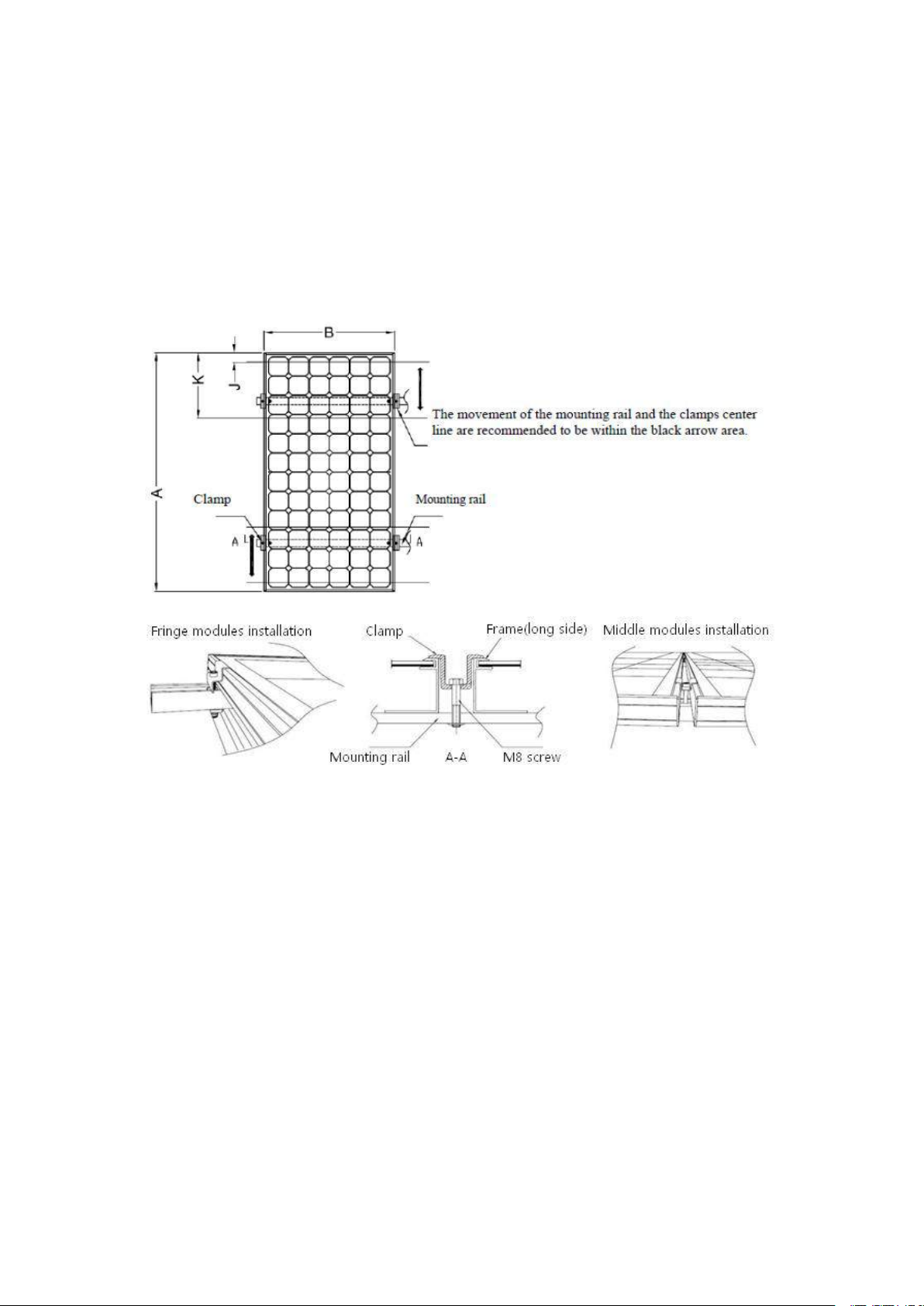
2.3.2 Fixation with clamps at long sides of frames
The module clamps should not come into contact with the front glass and must not
deform the frame. Be sure to avoid shadowing effects from the module clamps.
The module frame is not to be modified under any circumstances. When choosing
TPL ENERGY CO., LIMITED
FLAT 107, 25 INDESCON SQUARE, LONDON, UNITED KINGDOM
7
this type of clamp-mounting method, please be sure to use at least four clamps on
each module, two clamps should be attached on each long sides of the module.
Depending on the local wind and snow loads, if excessive pressure load is
expected, additional clamps or support would be required to ensure the module
can bear the load. The applied torque value should be big enough to fix the
modules steadily (Please consult with the clamp or support‟s supplier for the
specific torque value). Please find detailed mounting information in the below
illustration, the mounting place distance is suggested bigger than J and less than
Kas shown below in Figure 3&4.
Figure 3: PV module installed at long side with Clamp fitting method
TPL ENERGY CO., LIMITED
FLAT 107, 25 INDESCON SQUARE, LONDON, UNITED KINGDOM
8
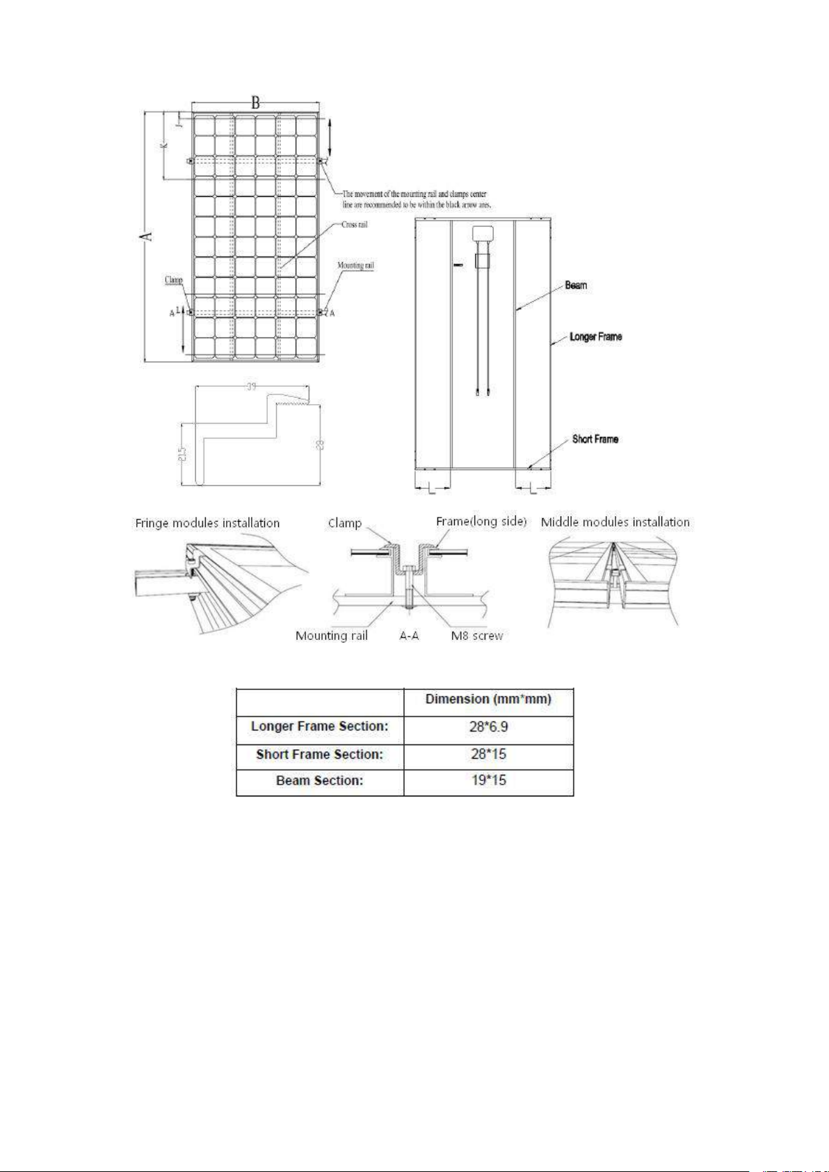
Figure 4: Light PV module installed at long side with Clamp fitting method
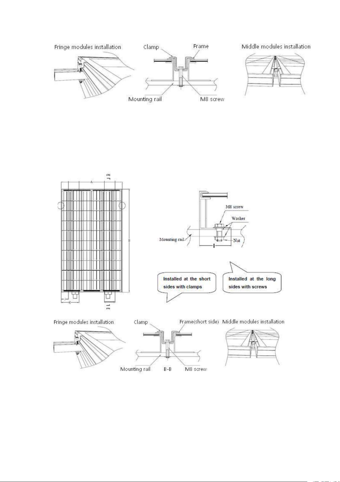
2.3.3 Fixation with clamps at short sides of the frames
The considerations and requirements about mounted by using clamps, please
refer to the instructions in 2.3.2, and find detailed mounting information in the
below illustration as Figure 5, the mounting place distance is suggested bigger
than J and less than K,as shown below.

TPL ENERGY CO., LIMITED
FLAT 107, 25 INDESCON SQUARE, LONDON, UNITED KINGDOM
9
Figure 5: PV module installed at short side with Clamp fitting method
2.3.4 Fixation with clamps at the long & short sides
The considerations and requirements about mounted by using clamps, please
refer to the instructions in 2.3.2, and find detailed mounting information in the
below illustration as Figure 6, the mounting place distance is suggested bigger
than J and the mounting place distance is suggested bigger than J and below.
TPL ENERGY CO., LIMITED
FLAT 107, 25 INDESCON SQUARE, LONDON, UNITED KINGDOM
10
Figure 6: PV module installed at long and short side with Clamp fitting method
2.3.5 Fixation with screws & clamps at the long & short sides
The considerations and requirements about mounted by using screws (clamps),
please refer to the instructions in 2.3.1 (2.3.2), and find detailed mounting
information in the below illustration as Figure 7, the mounting place distance on
short side is suggested bigger than J and less than K, as shown below.
Figure 7: PV module installed at long and short side with Screws and Clamps respectively
3. Wiring and connection
a) Before this procedure, please read the operation instructions of the PV system
carefully. Make wiring by Multi-connecting cables between the PV modules in
series or parallel connection, which is determined by user’s configuration

TPL ENERGY CO., LIMITED
FLAT 107, 25 INDESCON SQUARE, LONDON, UNITED KINGDOM
11
requirement for system power, current and voltage.
b) PV module connected in series should have similar current, and modules must
not be connected together to create a voltage higher than the permitted system
voltage. The maximum number of modules in series depends on system design,
the type of inverter used and environmental conditions.
c) The maximum fuse rating value in an array string can be found on the product
label or in the product datasheet. The fuse rating value is also corresponding to
the maximum reverse current that a module can withstand, i.e. when one string is
in shade then the other parallel strings of modules will be load by the shade string
and the current will pass through to create a current circuit. Thus based on the
maximum series fuse rating of module and local electrical installation criteria,
make sure the modules strings in parallel for connection need to be assembled
with appropriate string fuse for circuit protection.
d) Open the connection box of the control system and connect the cabled from the
PV arrays to the connection box in accordance with the installation indication of
the PV control systems. The cross-sectional area and cable connector capacity
must satisfy the maximum short-circuit of PV system (For a single component, we
recommended the cross-sectional area of cables is 4mm2and the rated current of
connectors is more than 10A), otherwise cables and connectors will become
overheating for large current. Please pay attention the temperature limit of cables
is 85℃.
e) All module frames and mounting racks must be properly grounded in
accordance with local and national electrical codes. Attach the equipment
grounding conductor to the module frame using the hole and hardware provided.
Not that a stainless steel star washer is used between the ground wire and module
frame (see Figure 8 below).This washer is used to avoid corrosion due to
dissimilar metals. Tighten the screw securely.
Figure 8: The graph of Grounding
f) Follow the requirements of applicable local and national electrical codes.
g) These modules contain factory installed bypass diode .if these modules are
incorrectly connected to each other, the bypass diodes, cable or junction box may
be damaged.

TPL ENERGY CO., LIMITED
FLAT 107, 25 INDESCON SQUARE, LONDON, UNITED KINGDOM
12
h) The cable of the junction box is defined as L, as showed below in Figure 9. For
TPL Solar standard module, L is 900/1200mm; and for customized module, L can
be based on your condition. Please take the cable length into consideration before
designing the wiring layout.
4. Maintenance and care
It is required to perform regular inspection and maintenance of the modules,
especially within warranty scope. To ensure optimum module performance,
recommends the following maintenance measures:
4.1 Visual Inspection
Inspect the Modules visually to find whether there are appearance defects, the
following need to be paid more attention especially:
a) Whether the glass is broken;
b) No sharp objects are in contact with the PV module surfaces
c) PV modules are not shaded by unwanted obstacles and/or foreign material
d) Corrosion along the cells’ bus-bar. The corrosion is caused by the dampness
infiltrated into the Modules because that the surface encapsulation materials are
damaged during the installation or transportation.
f) Whether there is burning vestige on the backsheet.
g) Check fixing screws and mounting brackets are tight, adjust and tighten as
necessary.
4.2 Cleaning
a) A built up of dust or dirt on the module(s) front face will result in a decreased
energy output. Clean the panel(s) preferably once per annum if possible (depend
on site conditions) using a soft cloth dry or damp, as necessary. Water with high
mineral content may leave deposits on the glass surface and is not recommended.
b) Never use abrasive material under any circumstances.
c) In order to reduce the potential for electrical and thermal shock, recommends
cleaning PV modules during early morning or late afternoon hours when solar
radiation is low and the modules are cooler, especially in regions with hotter
temperatures.
d) Never attempt to clean a PV module with broken glass or other signs of
exposed wiring, as this presents a shock hazard.
4.3 Inspection of Connector and Cable

TPL ENERGY CO., LIMITED
FLAT 107, 25 INDESCON SQUARE, LONDON, UNITED KINGDOM
13
It’s recommended to implement the following preventive maintenance every 6
months:
a) Check the sealing gels of the junction box to ensure it have no crack or crevice.
b) Examine the PV module(s) for signs of deterioration. Check all wiring for
possible rodent damage, weathering and that all connections are tight and
corrosion free. Check electrical leakage to ground.
5. Electrical specification
The module electrical rating are measured under Standard Test Conditions, which
are 1000W/m2, irradiance with AM 1.5 spectrum and 25 deg (77°F) ambient
temperature. The module might produce more or less voltage or current than
rating value in uncertainty condition.
6. Disclaimer of Liability
Because the use of the manual and the conditions or methods of installation,
operation, use and maintenance of photovoltaic (PV) product are beyond control,
TPL Solar does not accept responsibility and expressly disclaims liability for
loss ,damage, or expense arising out of or in any way connected with such
installation, operation, use or maintenance.
No responsibility is assumed by TPL Solar for any infringement of patents or other
rights of third parties, which may result from use of the PV product. NO license is
granted by implication or otherwise under any patent or patent rights.
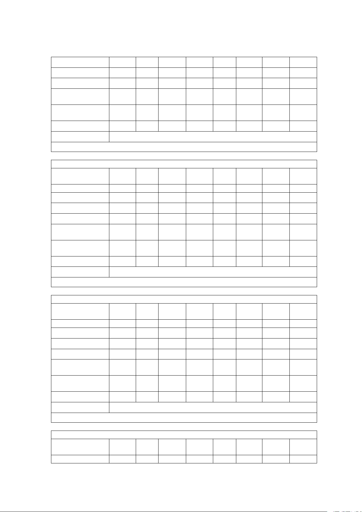
7. General product information
Product Electrical Rating at STC
Module Type
TPL255
P-72
TPL260
P-72
TPL265
P-72
TPL270
P-72
TPL275
P-72
TPL280
P-72
TPL285
P-72
TPL290
P-72
Open-circuit Voltage [V]
44.10
44.16
44.20
44.24
44.28
44.46
44.64
44.72
Short-circuit Current [A]
7.90
8.06
8.30
8.39
8.55
8.64
8.71
8.84
Voltage at Max. power [V]
36.24
36.28
36.32
36.48
36.72
36.90
37.08
37.16
Current at Max. power [A]
7.04
7.17
7.30
7.40
7.49
7.59
7.69
7.80
Max. Power (with
tolerance ±3%) [W]
255
260
265
270
275
280
285
290
Maximum System
Voltage [VDC]
1000
1000
1000
1000
1000
1000
1000
1000
Maximum Fuse Rating [A]
15
15
15
15
15
15
15
15
Module Application
Class A
*At STC (Standard Test Conditions): 1000 W/m2, 25℃cell temperature, AM 1.5 spectrum.
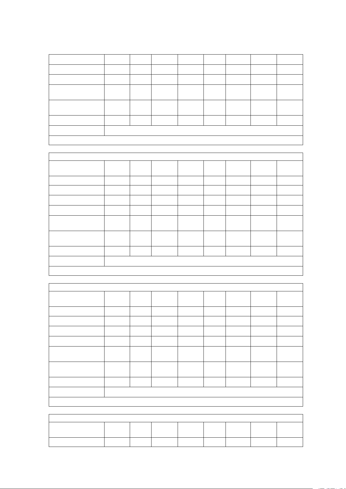
Product Electrical Rating at STC
Module Type
TPL295
P-72
TPL300
P-72
TPL305
P-72
TPL310
P-72
TPL315
P-72
TPL320
P-72
TPL325
P-72
TPL330
P-72
Open-circuit Voltage [V]
44.94
45.15
45.17
45.38
45.67
45.75
45.95
46.16
TPL ENERGY CO., LIMITED
FLAT 107, 25 INDESCON SQUARE, LONDON, UNITED KINGDOM
14
Short-circuit Current [A]
9.02
9.16
9.21
9.32
9.41
9.41
9.50
9.58
Voltage at Max. power [V]
37.38
37.59
37.78
37.87
38.02
38.25
38.47
38.69
Current at Max. power [A]
7.89
7.98
8.07
8.19
8.29
8.37
8.45
8.53
Max. Power (with
tolerance ±3%) [W]
295
300
305
310
315
320
325
330
Maximum System
Voltage [VDC]
1000
1000
1000
1000
1000
1000
1000
1000
Maximum Fuse Rating [A]
15
15
15
15
15
15
15
15
Module Application
Class A
*At STC (Standard Test Conditions): 1000 W/m2, 25℃cell temperature, AM 1.5 spectrum.
Product Electrical Rating at STC
Module Type
TPL335
P-72
TPL340
P-72
TPL345
P-72
TPL350
P-72
Open-circuit Voltage [V]
46.38
46.59
46.80
47.00
Short-circuit Current [A]
9.67
9.75
9.84
9.92
Voltage at Max. power [V]
38.93
39.13
39.39
39.55
Current at Max. power [A]
8.61
8.69
8.76
8.85
Max. Power (with
tolerance ±3%) [W]
335
340
345
350
Maximum System
Voltage [VDC]
1000
1000
1000
1000
Maximum Fuse Rating [A]
15
15
15
15
Module Application
Class A
*At STC (Standard Test Conditions): 1000 W/m2, 25℃cell temperature, AM 1.5 spectrum.
Product Electrical Rating at STC
Module Type
TPL215
P-60
TPL220
P-60
TPL225
P-60
TPL230
P-60
TPL235
P-60
TPL240
P-60
TPL245
P-60
TPL250
P-60
Open-circuit Voltage [V]
34.41
35.09
35.76
35.83
36.22
36.28
36.42
37.08
Short-circuit Current [A]
8.33
8.36
8.39
8.56
8.65
8.82
8.97
8.99
Voltage at Max. power [V]
29.36
29.95
30.40
30.60
30.87
30.90
30.93
31.46
Current at Max. power [A]
7.32
7.35
7.40
7.52
7.61
7.77
7.92
7.95
Max. Power (with
tolerance ±3%) [W]
215
220
225
230
235
240
245
250
Maximum System
Voltage [VDC]
1000
1000
1000
1000
1000
1000
1000
1000
Maximum Fuse Rating [A]
15
15
15
15
15
15
15
15
Module Application
Class A
*At STC (Standard Test Conditions): 1000 W/m2, 25℃cell temperature, AM 1.5 spectrum.
Product Electrical Rating at STC
Module Type
TPL255
P-60
TPL260
P-60
TPL265
P-60
TPL270
P-60
TPL275
P-60
TPL280
P-60
TPL285
P-60
TPL290
P-60
Open-circuit Voltage [V]
37.74
37.94
38.07
38.27
38.47
38.70
38.90
39.09

TPL ENERGY CO., LIMITED
FLAT 107, 25 INDESCON SQUARE, LONDON, UNITED KINGDOM
15
Short-circuit Current [A]
9.01
9.06
9.37
9.48
9.58
9.68
9.78
9.89
Voltage at Max. power [V]
31.74
32.28
31.83
32.03
32.24
32.49
32.69
32.88
Current at Max. power [A]
8.03
8.05
8.33
8.43
8.53
8.62
8.72
8.82
Max. Power (with
tolerance ±3%) [W]
255
260
265
270
275
280
285
290
Maximum System
Voltage [VDC]
1000
1000
1000
1000
1000
1000
1000
1000
Maximum Fuse Rating [A]
15
15
15
15
15
15
15
15
Module Application
Class A
*At STC (Standard Test Conditions): 1000 W/m2, 25℃cell temperature, AM 1.5 spectrum.
Product Electrical Rating at STC
Module Type
TPL205
P-56
TPL210
P-56
TPL215
P-56
TPL220
P-56
TPL225
P-56
TPL230
P-56
TPL235
P-56
TPL240
P-56
Open-circuit Voltage [V]
34.38
34.41
34.46
34.68
34.76
34.88
35.02
35.25
Short-circuit Current [A]
8.27
8.39
8.54
8.67
8.83
8.98
9.06
9.27
Voltage at Max. power [V]
28.12
28.38
28.60
28.84
28.89
29.12
29.20
29.53
Current at Max. power [A]
7.29
7.40
7.52
7.63
7.79
7.90
8.05
8.13
Max. Power (with
tolerance ±3%) [W]
205
210
215
220
225
230
235
240
Maximum System
Voltage [VDC]
1000
1000
1000
1000
1000
1000
1000
1000
Maximum Fuse Rating [A]
15
15
15
15
15
15
15
15
Module Application
Class A
*At STC (Standard Test Conditions): 1000 W/m2, 25℃cell temperature, AM 1.5 spectrum.
Product Electrical Rating at STC
Module Type
TPL245
P-56
TPL250
P-56
TPL255
P-56
TPL260
P-56
TPL265
P-56
TPL270
P-56
Open-circuit Voltage [V]
35.53
35.63
35.83
36.05
36.26
36.46
Short-circuit Current [A]
9.41
9.44
9.55
9.66
9.76
9.87
Voltage at Max. power [V]
29.57
29.80
30.04
30.27
30.46
30.66
Current at Max. power [A]
8.29
8.39
8.49
8.59
8.70
8.81
Max. Power (with
tolerance ±3%) [W]
245
250
255
260
265
270
Maximum System
Voltage [VDC]
1000
1000
1000
1000
1000
1000
Maximum Fuse Rating [A]
15
15
15
15
15
15
Module Application
Class A
*At STC (Standard Test Conditions): 1000 W/m2, 25℃cell temperature, AM 1.5 spectrum.
Product Electrical Rating at STC
Module Type
TPL195
P-54
TPL200
P-54
TPL205
P-54
TPL210
P-54
TPL215
P-54
TPL220
P-54
TPL225
P-54
TPL230
P-54
Open-circuit Voltage [V]
31.28
32.01
32.57
33.17
33.60
34.02
34.32
34.61

TPL ENERGY CO., LIMITED
FLAT 107, 25 INDESCON SQUARE, LONDON, UNITED KINGDOM
16
Short-circuit Current [A]
8.31
8.33
8.39
8.44
8.53
8.62
8.74
8.86
Voltage at Max. power [V]
27.08
27.28
27.32
27.68
27.86
27.92
28.07
28.20
Current at Max. power [A]
7.20
7.33
7.50
7.59
7.72
7.88
8.02
8.16
Max. Power (with
tolerance ±3%) [W]
195
200
205
210
215
220
225
230
Maximum System
Voltage [VDC]
1000
1000
1000
1000
1000
1000
1000
1000
Maximum Fuse Rating [A]
15
15
15
15
15
15
15
15
Module Application
Class A
*At STC (Standard Test Conditions): 1000 W/m2, 25℃cell temperature, AM 1.5 spectrum.
Product Electrical Rating at STC
Module Type
TPL235
P-54
TPL240
P-54
TPL245
P-54
TPL250
P-54
TPL255
P-54
TPL260
P-54
Open-circuit Voltage [V]
34.10
34.31
34.53
34.74
34.94
35.14
Short-circuit Current [A]
9.28
9.41
9.52
9.64
9.75
9.87
Voltage at Max. power [V]
28.49
28.69
28.93
29.15
29.35
29.55
Current at Max. power [A]
8.25
8.37
8.47
8.58
8.69
8.80
Max. Power (with
tolerance ±3%) [W]
235
240
245
250
255
260
Maximum System
Voltage [VDC]
1000
1000
1000
1000
1000
1000
Maximum Fuse Rating [A]
15
15
15
15
15
15
Module Application
Class A
*At STC (Standard Test Conditions): 1000 W/m2, 25℃cell temperature, AM 1.5 spectrum.
Product Electrical Rating at STC
Module Type
TPL170
P-48
TPL175
P-48
TPL180
P-48
TPL185
P-48
TPL190
P-48
TPL195
P-48
TPL200
P-48
TPL205
P-48
Open-circuit Voltage [V]
27.74
28.21
28.60
28.81
29.09
29.51
29.86
30.40
Short-circuit Current [A]
8.17
8.27
8.39
8.56
8.71
8.81
8.93
8.99
Voltage at Max. power [V]
24.16
24.19
24.32
24.52
24.72
24.79
27.28
27.32
Current at Max. power [A]
7.04
8.23
7.40
7.54
7.69
7.87
7.33
7.50
Max. Power (with
tolerance ±3%) [W]
170
175
180
185
190
195
200
205
Maximum System
Voltage [VDC]
1000
1000
1000
1000
1000
1000
1000
1000
Maximum Fuse Rating [A]
15
15
15
15
15
15
15
15
Module Application
Class A
*At STC (Standard Test Conditions): 1000 W/m2, 25℃cell temperature, AM 1.5 spectrum.
Product Electrical Rating at STC
Module Type
TPL210
P-48
TPL215
P-48
TPL220
P-48
TPL225
P-48
TPL230
P-48
Open-circuit Voltage [V]
30.45
30.58
30.78
31.00
31.20

TPL ENERGY CO., LIMITED
FLAT 107, 25 INDESCON SQUARE, LONDON, UNITED KINGDOM
17
Short-circuit Current [A]
9.41
9.45
9.58
9.71
9.84
Voltage at Max. power [V]
25.35
25.58
25.80
26.05
26.26
Current at Max. power [A]
8.29
8.41
8.53
8.64
8.76
Max. Power (with
tolerance ±3%) [W]
210
215
220
225
230
Maximum System
Voltage [VDC]
1000
1000
1000
1000
1000
Maximum Fuse Rating [A]
15
15
15
15
15
Module Application
Class A
*At STC (Standard Test Conditions): 1000 W/m2, 25℃cell temperature, AM 1.5 spectrum.
Product Electrical Rating at STC
Module Type
TPL130
P-36
TPL135
P-36
TPL140
P-36
TPL145
P-36
TPL150
P-36
TPL155
P-36
TPL160
P-36
TPL165
P-36
Open-circuit Voltage [V]
20.16
20.67
21.12
21.44
22.03
22.64
23.12
23.63
Short-circuit Current [A]
8.60
8.71
8.84
9.02
9.08
9.13
9.19
9.23
Voltage at Max. power [V]
16.56
17.13
17.57
17.58
18.03
18.26
18.78
19.21
Current at Max. power [A]
7.85
7.88
7.97
8.25
8.32
8.49
8.52
8.59
Max. Power (with
tolerance ±3%) [W]
130
135
140
145
150
155
160
165
Maximum System
Voltage [VDC]
1000
1000
1000
1000
1000
1000
1000
1000
Maximum Fuse Rating [A]
15
15
15
15
15
15
15
15
Module Application
Class A
*At STC (Standard Test Conditions): 1000 W/m2, 25℃cell temperature, AM 1.5 spectrum.
Product Electrical Rating at STC
Module Type
TPL170
P-36
TPL175
P-36
Open-circuit Voltage [V]
24.11
24.52
Short-circuit Current [A]
9.28
9.39
Voltage at Max. power [V]
19.65
20.09
Current at Max. power [A]
8.65
8.71
Max. Power (with
tolerance ±3%) [W]
170
175
Maximum System
Voltage [VDC]
1000
1000
Maximum Fuse Rating [A]
15
15
Module Application
Class A
*At STC (Standard Test Conditions): 1000 W/m2, 25℃cell temperature, AM 1.5 spectrum.
Product Electrical Rating at STC
Module Type
TPL100
P-28
TPL105
P-28
TPL110
P-28
TPL115
P-28
TPL120
P-28
TPL125
P-28
TPL130
P-28
TPL135
P-28
Open-circuit Voltage [V]
15.49
16.02
16.58
17.08
17.64
18.11
18.62
19.12

TPL ENERGY CO., LIMITED
FLAT 107, 25 INDESCON SQUARE, LONDON, UNITED KINGDOM
18
Short-circuit Current [A]
8.61
8.74
8.85
8.98
9.07
9.15
9.19
9.23
Voltage at Max. power [V]
12.36
12.95
13.38
13.87
14.27
14.59
15.10
15.57
Current at Max. power [A]
8.09
8.11
8.22
8.28
8.41
8.57
8.61
8.67
Max. Power (with
tolerance ±3%) [W]
100
105
110
115
120
125
130
135
Maximum System
Voltage [VDC]
1000
1000
1000
1000
1000
1000
1000
1000
Maximum Fuse Rating [A]
15
15
15
15
15
15
15
15
Module Application
Class A
*At STC (Standard Test Conditions): 1000 W/m2, 25℃cell temperature, AM 1.5 spectrum.
Product Electrical Rating at STC
Module Type
TPL165
S-72
TPL170
S-72
TPL175
S-72
TPL180
S-72
TPL185
S-72
TPL190
S-72
TPL195
S-72
TPL200
S-72
Open-circuit Voltage [V]
43.73
43.85
43.99
44.19
44.24
44.28
44.64
44.76
Short-circuit Current [A]
5.00
5.33
5.36
5.60
5.84
5.86
5.96
6.10
Voltage at Max. power [V]
35.80
36.17
36.34
36.36
36.68
36.72
37.08
37.20
Current at Max. power [A]
4.60
4.70
4.82
4.95
5.04
5.17
5.26
5.38
Max. Power (with
tolerance ±3%) [W]
165
170
175
180
185
190
195
200
Maximum System
Voltage [VDC]
1000
1000
1000
1000
1000
1000
1000
1000
Maximum Fuse Rating [A]
10
10
10
10
10
10
10
10
Module Application
Class A
*At STC (Standard Test Conditions): 1000 W/m2, 25℃cell temperature, AM 1.5 spectrum.
Product Electrical Rating at STC
Module Type
TPL205
S-72
TPL125
S-54
TPL130
S-54
TPL135
S-54
TPL140
S-54
TPL145
S-54
TPL150
S-54
TPL115
S-48
Open-circuit Voltage [V]
45.32
29.19
29.63
30.20
30.60
31.33
31.90
27.83
Short-circuit Current [A]
6.17
5.71
5.85
5.96
6.10
6.17
6.27
5.54
Voltage at Max. power [V]
37.77
24.51
25.15
25.67
26.03
26.71
27.23
16.64
Current at Max. power [A]
5.43
5.10
5.17
5.26
5.38
5.43
5.51
5.41
Max. Power (with
tolerance ±3%) [W]
205
125
130
135
140
145
150
115
Maximum System
Voltage [VDC]
1000
1000
1000
1000
1000
1000
1000
1000
Maximum Fuse Rating [A]
10
10
10
10
10
10
10
10
Module Application
Class A
*At STC (Standard Test Conditions): 1000 W/m2, 25℃cell temperature, AM 1.5 spectrum.
Product Electrical Rating at STC
Module Type
TPL120
S-48
TPL125
S-48
TPL130
S-48
TPL135
S-48
TPL80
S-36
TPL85
S-36
TPL90
S-36
TPL95
S-36
Open-circuit Voltage [V]
28.93
29.76
30.68
31.25
21.09
21.26
21.43
21.65
TPL ENERGY CO., LIMITED
FLAT 107, 25 INDESCON SQUARE, LONDON, UNITED KINGDOM
19
Short-circuit Current [A]
5.53
5.60
5.65
5.76
5.03
5.33
5.60
5.85
Voltage at Max. power [V]
17.34
17.93
25.15
25.67
18.00
18.09
18.18
18.36
Current at Max. power [A]
5.46
5.58
5.17
5.26
4.44
4.70
4.95
5.17
Max. Power (with
tolerance ±3%) [W]
120
125
130
135
80
85
90
95
Maximum System
Voltage [VDC]
1000
1000
1000
1000
1000
1000
1000
1000
Maximum Fuse Rating [A]
10
10
10
10
10
10
10
10
Module Application
Class A
*At STC (Standard Test Conditions): 1000 W/m2, 25℃cell temperature, AM 1.5 spectrum.
Product Electrical Rating at STC
Module Type
TPL100
S-36
TPL65
S-28
TPL70
S-28
TPL75
S-28
TPL80
S-28
Open-circuit Voltage [V]
21.86
14.28
15.18
15.74
16.71
Short-circuit Current [A]
6.10
6.07
6.15
6.35
6.38
Voltage at Max. power [V]
18.60
12.15
12.94
13.54
14.18
Current at Max. power [A]
5.38
5.35
5.41
5.54
5.64
Max. Power (with
tolerance ±3%) [W]
100
65
70
75
80
Maximum System
Voltage [VDC]
1000
1000
1000
1000
1000
Maximum Fuse Rating [A]
10
10
10
10
10
Module Application
Class A
*At STC (Standard Test Conditions): 1000 W/m2, 25℃cell temperature, AM 1.5 spectrum.
Product Electrical Rating at STC
Module Type
TPL265
M-72
TPL270
M-72
TPL275
M-72
TPL280
M-72
TPL285
M-72
TPL290
M-72
TPL295
M-72
TPL300
M-72
Open-circuit Voltage [V]
42.57
44.50
44.64
44.75
44.86
44.93
45.07
45.14
Short-circuit Current [A]
8.30
8.32
8.35
8.37
8.39
8.41
8.48
8.51
Voltage at Max. power [V]
35.94
36.15
36.35
36.51
36.65
36.95
37.39
37.66
Current at Max. power [A]
7.37
7.47
7.57
7.67
7.78
7.85
7.89
7.97
Max. Power (with
tolerance ±5%) [W]
265
270
275
280
285
290
295
300
Maximum System
Voltage [VDC]
1000
1000
1000
1000
1000
1000
1000
1000
Maximum Fuse Rating [A]
15
15
15
15
15
15
15
15
Module Application
Class A
*At STC (Standard Test Conditions): 1000 W/m2, 25℃cell temperature, AM 1.5 spectrum.
Product Electrical Rating at STC
Module Type
TPL305
M-72
TPL310
M-72
TPL315
M-72
TPL320
M-72
TPL325
M-72
TPL330
M-72
TPL335
M-72
TPL340
M-72
Open-circuit Voltage [V]
45.25
45.36
45.45
45.55
45.65
45.75
45.85
45.95

TPL ENERGY CO., LIMITED
FLAT 107, 25 INDESCON SQUARE, LONDON, UNITED KINGDOM
20
Short-circuit Current [A]
8.58
8.62
8.67
8.72
8.75
8.79
8.83
8.86
Voltage at Max. power [V]
38.03
38.32
38.61
38.89
39.17
39.48
39.79
40.10
Current at Max. power [A]
8.02
8.09
8.16
8.23
8.30
8.36
8.42
8.48
Max. Power (with
tolerance ±5%) [W]
305
310
315
320
325
330
335
340
Maximum System
Voltage [VDC]
1000
1000
1000
1000
1000
1000
1000
1000
Maximum Fuse Rating [A]
15
15
15
15
15
15
15
15
Module Application
Class A
*At STC (Standard Test Conditions): 1000 W/m2, 25℃cell temperature, AM 1.5 spectrum.
Product Electrical Rating at STC
Module Type
TPL345
M-72
TPL350
M-72
TPL220
M-60
TPL225
M-60
TPL230
M-60
TPL235
M-60
TPL240
M-60
TPL245
M-60
Open-circuit Voltage [V]
46.05
46.15
35.30
36.00
36.68
37.30
37.96
37.53
Short-circuit Current [A]
8.87
8.93
8.31
8.33
8.36
8.40
8.43
8.46
Voltage at Max. power [V]
40.40
40.70
27.82
28.30
28.58
28.87
29.17
31.02
Current at Max. power [A]
8.54
8.60
7.91
7.95
8.05
8.14
8.23
7.90
Max. Power (with
tolerance ±5%) [W]
345
350
220
225
230
235
240
245
Maximum System
Voltage [VDC]
1000
1000
1000
1000
1000
1000
1000
1000
Maximum Fuse Rating [A]
15
15
15
15
15
15
15
15
Module Application
Class A
*At STC (Standard Test Conditions): 1000 W/m2, 25℃cell temperature, AM 1.5 spectrum.
Product Electrical Rating at STC
Module Type
TPL250
M-60
TPL255
M-60
TPL260
M-60
TPL265
M-60
TPL270
M-60
TPL275
M-60
TPL280
M-60
TPL285
M-60
Open-circuit Voltage [V]
37.62
37.74
37.82
37.93
38.03
38.13
38.23
38.33
Short-circuit Current [A]
8.51
8.60
8.65
8.69
8.74
8.79
8.82
8.87
Voltage at Max. power [V]
31.38
31.76
31.99
32.32
32.61
32.90
33.22
33.50
Current at Max. power [A]
7.97
8.03
8.13
8.20
8.28
8.36
8.43
8.51
Max. Power (with
tolerance ±5%) [W]
250
255
260
265
270
275
280
285
Maximum System
Voltage [VDC]
1000
1000
1000
1000
1000
1000
1000
1000
Maximum Fuse Rating [A]
15
15
15
15
15
15
15
15
Module Application
Class A
*At STC (Standard Test Conditions): 1000 W/m2, 25℃cell temperature, AM 1.5 spectrum.
Product Electrical Rating at STC
Module Type
TPL290
M-60
TPL210
M-56
TPL215
M-56
TPL220
M-56
TPL225
M-56
TPL230
M-56
TPL235
M-56
TPL240
M-56
Open-circuit Voltage [V]
38.42
34.61
34.77
34.83
34.93
35.06
35.15
35.26
This manual suits for next models
14
Table of contents
Popular Inverter manuals by other brands

GYS
GYS MSW 82000 Translation of the original instructions

Jiangsu GoodWe Power Supply Technologu Co.
Jiangsu GoodWe Power Supply Technologu Co. GW06K-DT SEries user manual

YASKAWA
YASKAWA XGI 1000-65/65 Installation and operation guide

Tektronix
Tektronix AFG31000 Series Specification and Performance Verification Technical Reference

Kipor
Kipor KDE12EA Operation manual

Sofar
Sofar HYD 3000-EP user manual


