Frecon FR150A Series User manual

FR150A Series Multifunctional Compact Inverter
- 1 -
PREFACE
Thank you for choosing FRECON developed and produced FR150A series
multifunctional compact inverter.
FR150ASeries multifunction compact inverter is a compact, feature-rich, and highly
price-competitive models. Particularly suitable for electronic equipment, food packaging, woodworking,
treadmills and other small power transmission applications. This user manual presents a detailed
description of FR150Aseries multifunction compact inverter product characterization, structural
features, parameter setting, operation and commissioning, maintenance inspection, and other
contents. Make sure to carefully read the safety precautions before application, and use this product
on the premise that personnel and equipment safety is ensured.
IMPORTANT NOTES
◆To illustrate the details of some of the products ,in this manual have outer casing or safety
shields be removed picture .When using this product, please be sure to install a good outer
casing or covering, and in accordance with the contents of the manual operation.
◆The illustrations this manualfor illustration only andmay vary with different products you have
ordered.
◆The company is committed to continuous improvement of products, product features will
continue to upgrade, the information provided is subject to change without notice.
◆If you are using have questions, please contact our regional agents or our customer service
center. Customer Service Tel 0755 -33067999.
◆The company's other products please visit our website: .http://www.frecon.com.cn

FR150A Series Multifunctional Compact Inverter
- 2 -
TABLE OF CONTENTS
PREFACE ....................................................................................................................................- 1 -
TABLE OF CONTENTS................................................................................................................- 2 -
CHAPTER 1 PRODUCT INFORMATION......................................................................................- 3 -
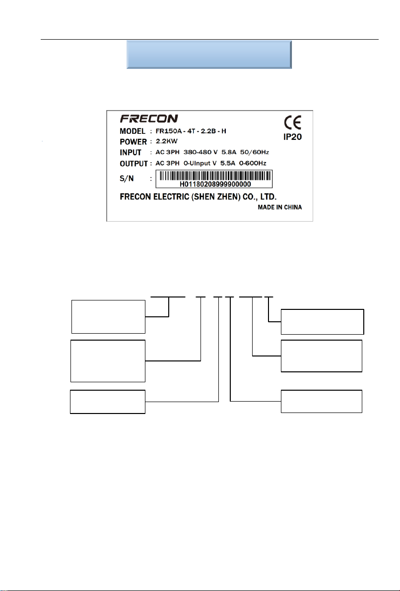
1.1 NAMEPLATE INFORMATION .....................................................................................................- 3-
1.2 INFORMATION OF FR150APRODUCT MODEL........................................................................... - 4-
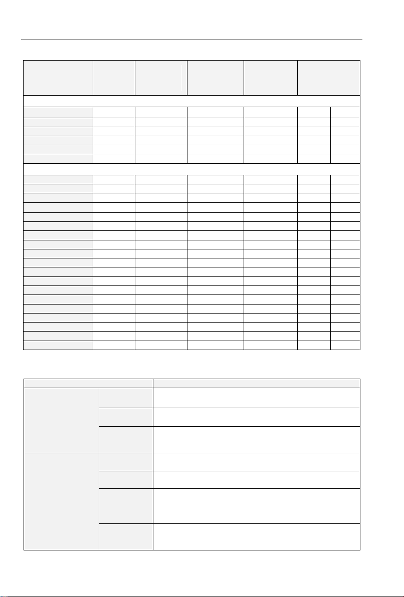
1.3 TECHNICAL FEATURES OF FR150A.........................................................................................- 4-
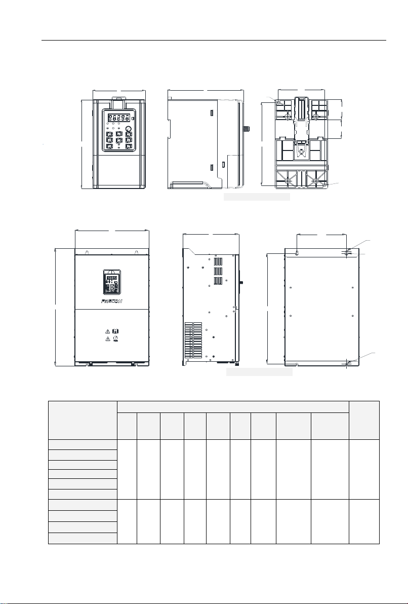
1.3 CONFIGURATION,MOUNTING DIMENSIONS AND WEIGHT............................................................- 7-
CHAPTER 2 WIRING AND TERMINALS......................................................................................- 9 -
2.1WIRING WAY.........................................................................................................................- 9-
2.2TERMINAL CONFIGURATION.................................................................................................. - 10 -
CHAPTER 3 OPERATION AND DISPLAY..................................................................................- 17 -
3.1 INTRODUCTION OF KEYPAD .................................................................................................. - 17 -
3.2VIEWING AND MODIFYING FUNCTION CODES.......................................................................... - 19 -
3.3 VIEWING STATUS PARAMETERS ............................................................................................- 20 -
3.4 MOTOR AUTO-TUNING.........................................................................................................- 20 -
3.5 PASSWORD SETTING........................................................................................................... - 20 -
3.6 KEYPAD LOCK ....................................................................................................................- 20 -
3.7 SHORTCUT MENUS FUNCTION CODE DESCRIPTION .................................................................. - 20 -
CHAPTER 4 LIST OF PARAMETER..........................................................................................- 22 -
4.1 FIVE LED (DIGITAL)DISPLAY INDICATORS............................................................................... - 23 -
4.2 STANDARD FUNCTION PARAMETERS .....................................................................................- 23 -
4.3 PULSE FEEDBACK...............................................................................................................- 48 -
CHAPTER 5 MAINTENANCE AND TROUBLESHOOTING........................................................- 49 -
APPENDIX A: MODBUS COMMUNICATION PROTOCOL ........................................................- 53 -
APPENDIX B: BRAKING RESISTOR.........................................................................................- 59 -

FR150A Series Multifunctional Compact Inverter
- 3 -
Chapter 1 Product Information
1.1 Nameplate information
Fig.1-1 Nameplate information
Model Explanation
Model show on product nameplate contains information below
FR150□-4T-0.7B
Master series code of
product:
FR150:Multifunctional
Compact Inverter
Input voltage:
2:220V(-15%~+20%)
4:380V(-15%~+30%)
Input voltage phases:
S:Single-phase
T:Three-phase
Brake unit:
B: Built-in brake unit
Adaptable Motor (kW)And
Type of
Motor:0.7:0.75kW(General
type)
Industry-specific series
code:
A:Standard Machine
B~Z:Industry-specific
retention
Fig.1-2 Model Explanation

FR150A Series Multifunctional Compact Inverter
- 4 -
1.2 Information of FR150A Product Model
Table 1-1 FR150A Product model and technical data
Model
Power
capacity
KVA
Rated input
current
A
Rated output
current(heavy
load)A
Rated
output
current(light
load)A
Adaptive motor
kW HP
Single phase:220V,50/60Hz Range:-15%~+30%
FR150A-2S-0.2B
0.5
4.9
1.6
2.5
0.25
0.25
FR150A-2S-0.4B
1.0
6.5
2.5
3
0.37
0.5
FR150A-2S-0.7B
1.5
9.3
4.2
4.6
0.75
1.0
FR150A-2S-1.1B
1.1
11
5.5
6.5
1.1
1.5
FR150A-2S-1.5B
3.0
15.7
7.5
8.5
1.5
2
FR150A-2S-2.2B
4.0
24
9.5
10.5
2.2
3
Three phase:380V,50/60Hz Range:-15%~+30%
FR150A-4T-0.7B
1.5
3.4
2.5
3
0.75
1
FR150A-4T-1.5B
3.0
5.0
4.2
4.6
1.5
2
FR150A-4T-2.2B
4.0
5.8
5.5
6.5
2.2
3
FR150A-4T-4.0B
6.0
11
9.5
10.5
3.7、4
5
FR150A-4T-5.5B
8.9
14.6
13
17
5.5
7.5
FR150A-4T-7.5B
11
20.5
17
20
7.5
10
FR150A-4T-011B
17
26
25
32
11
15
FR150A-4T-015B
21
35
32
37
15
20
FR150A-4T-018B
24
38.5
37
45
18.5
25
FR150A-4T-022B
30
46.5
45
49
22
30
FR150A-4T-030B
40
62
60
75
30
40
FR150A-4T-037B
57
76
75
82
37
50
FR150A-4T-045
69
92
91
112
45
60
FR150A-4T-055
85
113
112
134
55
70
FR150A-4T-075
114
157
150
168
75
100
FR150A-4T-090
134
186
176
210
90
125
FR150A-4T-110
160
220
210
253
110
150
FR150A-4T-132
192
260
253
304
132
175
FR150A-4T-160
231
310
304
340
160
210
1.3 Technical Features of FR150A
Table 1-2 Technical features of FR150A
Project
Specifications
Power input
Rated input
voltage (V)
1-Phase 220V (-15%~+20%)
3-phase 380 V (-15%~+30%)
Rated input
current (A)
See table 1-1
Rated input
frequency
(Hz)
50Hz/60Hz,tolerance±5%
Power output
Applicable
motor (kW)
See table 1-1
Rated output
current (A)
See table 1-1
The
maximum
output
voltage (V)
0~rated input voltage, error<±3%
The
maximum
output
0.00~600.00 Hz,unit0.01Hz

FR150A Series Multifunctional Compact Inverter
- 5 -
frequency
(Hz)
Control
characteristics
V/f patterns
V/f control
Sensor-less vector control 1
Sensor-less vector control 2
Speed range
1:50 (V/f control)
1:100 (sensor-less vector control 1)
1:200 (sensor-less vector control 2)
Speed
accuracy
±0.5% (V/f control)
±0.2% (sensor-less vector control 1、2 )
Speed
fluctuation
±0.3% (sensor-less vector control 1、2 )
Torque
response
< 10ms (sensor-less vector control 1、2 )
Starting
torque
0.5Hz: 180% (V/f control, sensor-less vector control 1)
0.25Hz:180%(sensor-less vector control 2)
Basic functions
Carrier
frequency
0.7kHz~16kHz
Overload
capability
G Model:150% Rated Current 60s,180% Rated Current
10s,200% Rated Current 1s.
Torque boost
Automatic torque boost;Manual torque boost 0.1%~
30.0%
V/F Curve
Three ways: Three ways: straight; multi-point type; N
Th-type V / F curve(1.2Th -type、1.4Th -type、1.6Th -type、
1.8Th -type、2Th -type)
Acceleration
and
deceleration
Curve
Line or curve acceleration and deceleration mode.
Four kinds of acceleration and deceleration time,Ramp
Time Range :0.0~6000.0s
DC brake
DC brake start frequency: 0.00~600.00Hz
DC brake time:0.0s~10.0s
DC brake current:0.0%~150.0%
Basic functions
Jog brake
Jog frequency range:0.00Hz~50.00Hz.
Jog deceleration time: 0.0s~6000.0s.
Simple PLC、
Multi-speed
Through the built-in PLC or control terminal to achieve up
to 16 speed running
Built-in PID
Facilitate the realization of process control loop control
system
Automatic
voltage
adjustment
(AVR)
When the grid voltage changes, can automatically maintain
a constant output voltage
Fast current
limit function
Minimize over current fault protection inverter running
Over voltage
Over current
System automatically limits of current and voltage during
operation to prevent frequent
Run
Command
source
Given the control panel, control terminal, serial
communication port given.
Frequency
given
9 kinds of frequency sources: digital setting, keyboard
potentiometer setting, analog
Voltage, given analog current reference pulse is given, the
serial port is given, multi-speed given, PLC is given, the
process PI D reference. There are several ways to switch
Protection
function
Provide fault protection dozen: Overcurrent、Overvoltage、Undervoltage、
Overtemperature、Overload Etc Protection.

FR150A Series Multifunctional Compact Inverter
- 6 -
Display and
keyboard
LED Display
Display Parameters
Key lock and
function
selection
Realize some or all of the keys locked, scope definition
section keys to prevent misuse
Run and stop
monitoring
information
In the run or stop can be set to monitor U00 group four
objects were.
Environment
Place of
operation
Indoors, no direct sunlight, free from dust, corrosive
gases,
flammable gases, oil mist, water vapor, water drop and
salt, etc.
Altitude
0~2000m
De-rate 1% for every 100m when the altitude is above
1000 meters
Ambient
temperature
-10℃~40℃
Relative
humidity
5~95%, no condensation
Vibration
Less than 5.9m/s2 (0.6g)
Storage
temperature
-20℃~+70℃
Others
Efficiency
Rated power≥93%
Installation
Wall-mounted or DIN-rail mounting
IP grade
IP20
Cooling
method
Fan cooled

FR150A Series Multifunctional Compact Inverter
- 7 -
1.3 Configuration, Mounting Dimensions and Weight
◆FR150A (0.2~22kW)
W
H
DW1
H1
H3
H2
d2
d1
Fig 1-3 FR150A (0.2~22kW) product size diagram
◆FR150A (30~160kW)
H
D
WW1
H1
d1
d1
d2
Fig 1-3 FR150A (30~160kW) product size diagram
Table 1-3 Configuration, mounting dimensions and weight
Model.
External and Install dimensions (mm)
N.W
(kg)
W
H
D
W1
H1
H2
H3
Install
hole
d1
Install
hole
d2
FR150A-2S-0.2B
75
150
120
65
140
35
38.5
4.5
4.5
0.95
FR150A-2S-0.4B
FR150A-2S-0.7B
FR150A-2S-1.1B
FR150A-4T-0.7B
FR150A-4T-1.5B
FR150A-2S-1.5B
93
171
132
82
160
35
39
4.5
4.5
1.46
FR150A-2S-2.2B
FR150A-4T-2.2B
FR150A-4T-4.0B

FR150A Series Multifunctional Compact Inverter
- 8 -
Model.
External and Install dimensions (mm)
N.W
(kg)
W
H
D
W1
H1
H2
H3
Install
hole
d1
Install
hole
d2
FR150A-4T-5.5B
117
187
160
102
172
-
-
4.7
4.7
2.5
FR150A-4T-7.5B
FR150A-4T-011B
146
249
174
131
236
-
-
5.5
5.5
3.9
FR150A-4T-015B
198
300
182
183
287
-
-
5.5
5.5
6.2
FR150A-4T-018B
FR150A-4T-022B
FR150A-4T-030B
245
390
187
200
375
-
-
7
13
11.6
FR150A-4T-037B
FR150A-4T-045
300
485
226
200
581
-
-
7
13
14.8
FR150A-4T-055
FR150A-4T-075
335
600
236
200
581
-
-
9.5
17.5
22.8
FR150A-4T-090
310
620
280
200
601
-
-
9.5
17.5
25
FR150A-4T-110
310
650
309
200
620
-
-
11.5
22
40
FR150A-4T-132
FR150A-4T-160
400
750
320
300
723
-
-
11.5
22
69

FR150A Series Multifunctional Compact Inverter
- 9 -
Chapter 2 Wiring and Terminals
2.1 Wiring way
2.1.1Single-phase 220V inverter typical wiring diagram
L
24V
DI1
DI2
DI3
DI4
DI7/HI
GND
+10V
AI1
AI2
GND
PE
U
V
W
AO1
GND
485+
485-
GND
R1A
R1B
R1C
MCCB
1kΩ~5kΩ
DC 0~10V
DC 0~10V or 0~20mA
Single-phase
220V
50/60Hz M
AI2
I
V
RS485
ON
OFF
(-) (+) PB
Braking resistor
FR150A
24V
Y1
N
Switch input 1
Switch input 2
Switch input 3
Switch input 4
High-speed
pulse input HI
Analog Output 0~10V
Open collector
output 1
Relay output 1
250V AC/3A
30V DC1A
RS485
Communication
PLC
Fig.2-1 Single-phase 220V Inverter wiring diagram
Remarks:
1)◎refers to main circuit terminals.,○refers to control circuit terminals.
2)User selects braking resistor based on real needs,Please refer to the braking resistor Selection
Guide.
3)Signal cable and power cable should be separated. Try to cross control cable and
power cable in 90°if needed. The best selection of analog signal lines shielded twisted pair,Power
cables use shielded three-core cable(The specifications of the motor cable than ordinary freshman
profile)or Comply with manual drive.

FR150A Series Multifunctional Compact Inverter
- 10 -
2.1.2 Three-phase 380V inverter typical wiring diagram
R
24V
DI1
DI2
DI3
DI4
DI7/HI
GND(<5.5kW)/
COM(≥5.5kW)
+10V
AI1
AI2
GND
PE
U
V
W
AO1
GND
485+
485-
GND
R1A
R1B
R1C
MCCB
1kΩ~5kΩ
DC 0~10V
DC 0~10V or 0~20mA
Three-phase
380V
50/60Hz M
AI2
I
V
RS485
ON
OFF
(-) (+) PB
Braking resistor
FR150A
24V
Y1
S
Switch input 1
Switch input 2
Switch input 3
Switch input 4
High-speed
pulse input HI
Analog Output 0~10V
Open collector
output 1
Relay output 1
250V AC/3A
30V DC1A
RS485
Communication
T
PLC
Fig.2-2 Three-phase 380V Inverter wiring diagram
2.2 Terminal Configuration
2.2.1 Main Circuit Terminals
◆0.2~1.1kW Main Circuit Terminals
Fig.2-3 0.2~1.1kW main circuit terminals

FR150A Series Multifunctional Compact Inverter
- 11 -
◆0.7~4.0kW Main Circuit Terminals :
Fig.2-4 0.7~4.0kW Main Circuit Terminals
◆5.5~7.5 kW Main Circuit Terminals:
(+) (-) RST UV
POWER
Fig.2-5 5.5~7.5kW Main Circuit Terminals
◆11~22 kW Main Circuit Terminals:
PB
(+) (-)
RFI
DC
Fig.2-6 11~22kW Main Circuit Terminals
◆30~37kW Main Circuit Terminals:
PB
(+) (-)
DC
Fig.2-7 30~37kW Main Circuit Terminals

FR150A Series Multifunctional Compact Inverter
- 12 -
◆45~90kW Main Circuit Terminals:
PB
(+) (-)
DC
Fig.2-8 45~90kW Main Circuit Terminals
Power
Recommended
power cablemm2
Recommended
lug model
Terminal
width mm
Tightening
torque N.m
37kW
25
GTNR25-8
18
10
45kW
35
GTNR35-8
18
10
55kW
50
GTNR50-8
18
10
75kW
70
GTNR70-8
23
10
90kW
70
GTNR70-8
23
10
◆110~132kW Main Circuit Terminals:
Fig.2-9 110~132kW Main Circuit Terminals
Power
Recommended
power cablemm2
Recommended
lug model
Terminal
width mm
Tightening
torque N.m
110kW
120
GTNR120-12
31
35
132kW
150
GTNR150-12
31
35
◆160kW Main Circuit Terminals:
Fig.1-11 160kW Main Circuit Terminals
Power
Recommended
power cablemm2
Recommended
lug model
Terminal
width mm
Tightening
torque N.m
160kW
150
GTNR150-12
31
35

FR150A Series Multifunctional Compact Inverter
- 13 -
Table 2-1 main circuit terminal functions
Terminal marks
Designation and function of terminals.
R、S、T
Three-phase 380VAC power input terminals
L、N
Single-phase 220V AC power input terminals
U、V、W
AC output terminals of inverter for connecting to 3-phase induction motor.
(+)、(-)
Positive and negative terminals of internal DC bus.
PB
Positive and negative terminals of internal DC bus. Connecting terminals
of braking resistor. One end connected to + and the other to PB.
Grounding terminal.
Remarks: No phase sequence requirements on wiring of the input side of inverter. Wiring
Precautions:
1)Power input terminals (R、S 、T)/(L、N)
◆The cable connection on the input side of the AC drive has no phase sequence requirement.
2)DC bus (+)、(-)
◆Terminals (+) and (-) of DC bus have residual voltage after the AC drive is switched off. After
indicator CHARGE goes off, wait at least 10 minutes before touching the equipment Otherwise, you
may get electric shock.
◆Do not connect the braking resistor directly to the DC bus. Otherwise, it may damage the AC drive
and even cause fire.
3)Braking resistor connection terminals (+)、PB
◆The cable length of the braking resistor shall be less than 5 m. Otherwise, it may damage the AC
drive.
4)AC drive output terminals U、V、W
◆The capacitor or surge absorbercannot be connected to the output side of the AC drive. Otherwise,
it may cause frequent AC drive fault or even damage the AC drive.
If the motor cable is too long, electrical resonance will be generated due to the impact of distributed
capacitance. This will damage the motor insulation or generate higher leakage current, causing the AC
drive to trip in overcurrent protection. If the motor cable is greater than 100 m long, an AC output
reactor must be installed close to the AC drive.
5)Terminal PE
◆This terminal must be reliably connected to the main earthing conductor. Otherwise, it may cause
electric shock, mal-function or even damage to the AC drive.
◆Do not connect the earthing terminal to the neutral conductor of the power supply.

FR150A Series Multifunctional Compact Inverter
- 14 -
2.1.2 Control circuit terminals
◆Control circuit terminals(<5.5kW):
DI1
+24V
DI2 DI3 DI4
+10V
R1A R1B R1C
AI1 AI2
485+
AO1
GND
DI7/HI
Y1
GND
485-
PLC
Fig.2-5 Control circuit terminals (<5.5kW)
Table 2-2 FR150A Description of control circuit terminals
Type
Terminal
Name
Function Description
Power supply
+10V-GND
External +10 V
power supply
Provide +10 V power supply to
external unit.
Generally, it provides power supply to
external potentiometer with resistance
range of 1–5 kΩ.
Maximum output current: 10 mA
+24V-GND
External +24V
power
supply Applying
to Overvoltage
Category II
circuit
Provide +24 V power supply to
external unit.
Generally, it provides power supply to
DI/Do terminals and external sensors.
Maximum output current: 200 mA
PLC
Input terminal
of
external power
supply
Connect to +24 V by default.
When DI1-DI7 need to be driven by
external signal, PLC needs to be
connected to external power supply
and be disconnected from +24 V.
Analog input
AI1-GND
Analog input 1
Input voltage range: DC 0~10V/0~
20mA,decided by toggle switches
AI1、AI2 on the control board
Impedance: 250 kΩ (voltage input),
250 Ω (current input)
AI2-GND
Analog input 2
Switch input
DI1- GND
Switch input
terminals 1
Maximum input frequency:200Hz
Impedance:2.4kΩ
Voltage range for level input:9V~30V
DI2- GND
Switch input
terminals 2
DI3- GND
Switch input
terminals 3
DI4- GND
Switch input
terminals 4
DI7/HI-GND
Switch input
terminals 7 OR
High-speed
pulse input
Besides features of DI1–DI4, it can be
used for high-speed pulse input.
Maximum input frequency: 100 kHz
Analog
output
AO1-GND
Analog output
terminal 1
Output voltage range:0~10V
Impedance requirements≥10kΩ
Switch output
Y1-GND
Open collector
output 1
Voltage range:0~24V
Current range:0~50mA
Relay output
R1A-R1C
Normally open
Contact driving capacity:

FR150A Series Multifunctional Compact Inverter
- 15 -
terminal
AC250V,3A,COSØ=0.4.
DC 30V,1A
R1B-R1C
Normally
closed terminal
485
Communication
485+,485-
485
Communication
Terminals
Rate:
4800/9600/19200/38400/57600/
115200bps
Termination resistor is set by the
toggle switch on the control panel
RS485
GND
485
Communication
shielded
ground
Shield
PE
Shield Ground
Ground terminal for shield
Auxiliary
Interface
External
operation
panel interface
Use standard network cable
Maximum cable distance: 50m
◆Control circuit terminals(≥5.5kW):
Fig.2-6 Control circuit terminals (≥5.5kW)
Type
Terminal
Name
Function Description
Power supply
+10V-GND
External +10 V
power supply
Provide +10 V power supply to
external unit.
Generally, it provides power supply to
external potentiometer with resistance
range of 1–5 kΩ.
Maximum output current: 10 mA
+24V-COM
External +24V
power supply
Applying
to Overvoltage
Category II
circuit
Provide +24 V power supply to
external unit.
Generally, it provides power supply to
DI/Do terminals and external sensors.
Maximum output current: 200 mA
PLC
Input terminal
of external
power
supply
Connect to +24 V by default.
When DI1-DI7 need to be driven by
external signal, PLC needs to be
connected to external power supply
and be disconnected from +24 V.
Analog input
AI1-GND
Analog input 1
Input voltage range: DC 0~10V/0~
20mA,decided by toggle switches
AI1、AI2 on the control board
Impedance: 250 kΩ (voltage input),
250 Ω (current input)
AI2-GND
Analog input 2
Switch input
DI1- COM
Switch input
terminals 1
Maximum input frequency:200Hz
Impedance:2.4kΩ
Voltage range for level input:9V~30V
DI2- COM
Switch input
terminals 2
DI1
+24V
DI2
DI3
DI4
+10V
R1A
R1B
R1C
AI1
AI2
485+
AO1
GND
DI7/HI
Y1
COM
485-
PLC

FR150A Series Multifunctional Compact Inverter
- 16 -
DI3- COM
Switch input
terminals 3
DI4- COM
Switch input
terminals 4
DI7/HI-COM
Switch input
terminals 7 OR
High-speed
pulse input
Besides features of DI1–DI4, it can be
used for high-speed pulse input.
Maximum input frequency: 100 kHz
Analog
output
AO1-GND
Analog output
terminal 1
Output voltage range:0~10V
Impedance requirements≥10kΩ
Switch output
Y1-COM
Open collector
output 1
Voltage range:0~24V
Current range:0~50mA
Relay output
R1A-R1C
Normally open
terminal
Contact driving capacity:
AC250V,3A,COSØ=0.4.
DC 30V,1A
R1B-R1C
Normally
closed terminal
485
Communication
485+,485-
485
Communication
Terminals
Rate:
4800/9600/19200/38400/57600/
115200bps
Termination resistor is set by the
toggle switch on the control panel
RS485
GND
485
Communication
shielded
ground
Shield
PE
Shield Ground
Ground terminal for shield
Auxiliary
Interface
External
operation
panel interface
Use standard network cable
Maximum cable distance: 50m

FR150A Series Multifunctional Compact Inverter
- 17 -
Chapter 3 Operation and display
3.1 Introduction of Keypad
As a human-machine interface, you can modify the parameters, monitor the working status and
start or stop the inverter by operating the keypad. Its appearance and function area as shown in the
following figure:
Fig.3-1 Keypad
3.1.1 Key and potentiometer Functions on keypad
There are 8 keys and a potentiometer on the keypad, whose functions are as shown in Table 3-1.
Table 3-1 Key functions on keypad
Symbol
Name
Function
Escape
Enter or exit Level I menu
Enter
Enter the menu interfaces level by level, and
confirm the parameter setting
Increment
Increase data or function code
Decrement
Decrease data or function code
Shift
Select the displayed parameters in turn in the stop
or running state, and select the digit to be modified
when modifying parameters
Multifunction
Perform function switchover (such as jog run and
quick switchover of
command source or direction) according to the
setting of F16.00
Run
Start the inverter in the keypad control mode
Stop/Reset
Stop the inverter when it is in the running state and
perform the reset operation when it is in the fault
state. The functions of this key are restricted in
F16.01.
+
Key combinations
The inverter will free stop when the run and stop
key are pressed simultaneously

FR150A Series Multifunctional Compact Inverter
- 18 -
3.1.2 Keypad Indicators
There are 8 Indicators on the keypad, whose descriptions are as shown in Table 3-2.
Table 3-2 Description of indicators
Indicator
Name
Meaning
Unit
Hz
Frequency
ON: currently displayed parameter is
frequency
V
Voltage
ON: currently displayed parameter is voltage
A
Current
ON: currently displayed parameter is current
%
Percentage
ON: currently displayed parameter is
percentage
All off
Other unit
Other unit or no unit
State
FWD/REV
Forward or
reverse
ON: the drive is running reverse
OFF: the drive is running forward
Flash: dormant state
LOC/REM
Keypad,
terminals or
communication
ON: Terminal control
OFF: Keypad control
Flash: Communication control
(Green border)
Running state
ON: Running state
OFF: Stopped state
Flash: In process of stop
(Red border)
Fault state
ON: Fault state
OFF: Normal state
Flash: Warning state
3.1.3 Keypad digital display
The keypad has five LED (digital) display, it can display a given frequency, output frequency and
other parameters, monitoring data and alarm code. Table 3-3 shows meanings of the characters
displayed on Keypad.
Table 3-3 Meanings of displayed characters
Displayed
character
Character
Meaning
Displayed
character
Character
Meaning
Displayed
character
Character
Meaning
Displayed
character
Character
Meaning
0
A
I
S
1
b
J
T
2
C
K
t
3
c
L
U
4
d
N
u
5
E
n
y
6
F
o
-
7
G
p
8.
8
H
q
.
9
h
r

FR150A Series Multifunctional Compact Inverter
- 19 -
3.1.4 Message status
A message appears when the state of completion of certain operations. Prompt message
characters and their meanings are specified in Table 3-4.
Table 3-4 Prompt characters
Prompt symbol
Meaning
Prompt symbol
Meaning
Err00~Err99
Fault type
TUNE
Motor parameter
identification in
process
A00~A99
Alarm type
-END-
Write parameter
3.2 Viewing and Modifying Function Codes
The keypad of the FR150Aadopts three-level menu.
◆The three-level menu consists of function code group (Level I), function code (Level II), and
function code setting value (level III), as shown in the figure 3-2.
ESC
50.00 F00
Status parameter
(default display)
Switch menu
Level-I menu
(Select the function
code group)
F00.04
ENT
Enter
ESCESC
Return
Level-II menu
(Select the function
code)
0
ENT
Enter
ESCESC
Not to
Save the
setting
Level-III menu
(Set the value of
the function code)
F00.05
ENT
To save the
setting
Next function
code
ESCESC
Return
ENT
Enter
If there is a blinking digit,press
to modify the digit
11.2
Switch
Status parameter
Fig.3-3 Operation procedure on the keypad
Explanation: In the level III menu, you can press the ESC key or ENT key to return to the level II
menu. The difference is: If you do not have to modify the function code setting, press ENT will be
automatically transferred to the next function code; If the function code settings are modified, it will
display menu "-END-" 1 second when press ENT key, and redisplay the current function code settings,
and it will be automatically transferred to the next function code when press the ENT key again. Press
the ESC key to abandon the current parameter changes directly returns the current function code in
level II.
◆Here is an example of changing the value of F01-02 to 15.00 Hz.
ESC
50.00 F00.00 ESC F00 F01 F01.00
ENT
F01.02
10.00
ENT
10.00
ENT
F01
ESC
F01.02
ESC
F01.03
ESC ENT 15.00
ESC
15.00
Fig.3-4 Example of changing the parameter value
In Level III menu, if the parameter has no blinking digit, it means that the parameter cannot be
modified. This may be because:
(1)Such a function code is onlyreadable, such as, AC drive model, actually detected parameter
and running record parameter.
(2)Such a function code cannot be modified in the running state and can only be changed at
stop.

FR150A Series Multifunctional Compact Inverter
- 20 -
3.3 Viewing Status Parameters
There are stop state parameters and running state parameters.
It has 4 status parameters in the stop or running state .You can press “>>” on the keypad to display
status parameters. Which parameters are displayed is determined by the values of F16.03~F16.06
(Running state parameters 1~4)、 F16.07~F16.10(stop state parameters1~4), it can select the
U00 group.
3.4 Motor Auto-tuning
Tuning is valid only when the keyboard command mode. Set tuning mode (stationary or rotating),
press the ENT key to confirm, the keyboard will display TUNE, then press the RUN key, the inverter
will drive motor acceleration and deceleration, positive inversion operation,and the run indicator lights.
Tuning duration of about two minutes, when the display TUNE message disappears, returning to
normal parameter display status, which means that the tuning is completed.
3.5 Password Setting
The inverter provides password protection function, it is set a user's password when F00.00 set to
nonzero. If five minutes without operating the keypad, the password protection is effective, and the
keypad will show “-----”, then the user must enter the correct password to enter the regular menu,
otherwise inaccessible.
There are three ways a user password into force:
Method 1: Set F00.00 parameter to nonzero, then press the ESC + ENT key.
Method 2: Set F00.00 parameter to nonzero, then do not use the keypad within five minutes.
Method 3: Set F00.00 parameter to nonzero, then completely power down and then power.
If you want to cancel the password protection functions, only through a password to enter, and set
F00.00 to 0.
3.6 Keypad lock
3.6.1 Keypad lock
The following three methods to any one immediately lock all or part of the keypad buttons; see the
definition of the function code F16.02.
Method 1:Set F16.02parameter to nonzero, then press the ESC + ENT key.
Method 2:Set F16.02 parameter to nonzero, and then do not use the keypad within five minutes.
Method 3:Set F16.02 parameter to nonzero, then completely power down and then power.
3.6.2 Keypad unlock
Press the ESC + >> keys to unlock. Unlocking operation does not change the value of F16.02,
That means when Meet the keypad locking conditions, the keypad will be locked again. If you want the
control panel no longer be locked, after unlocking the F16.02 must change the value to 0.
3.7 Shortcut menus function code description
Factory setting mode is changed to be shortcut menu mode (F00.01=1) in the software
version above V1.07, group 17 is for the parameters of shortcut menu.
The difference of display between shortcut manual and basic menu is in the second level
menu, please refer to below the details of difference and the switching method.
Menu mode
Shortcut menu
Basic menu
Display
difference
F01.01.
The last digit of F01.01. function
code is with radix point, no
flashing
F01.01 function code is
without radix point, and flashing
Function
difference
1. Press or for
up-down switch in F17 function
code
2. can’t return back to
first level menu
1. Press or up-down switch in
sequency
2. Press return back to first level
menu
F01.01
This manual suits for next models
25
Table of contents
Other Frecon Inverter manuals
Popular Inverter manuals by other brands

Omnik
Omnik Omniksol-3k-TL2 user manual

CEA
CEA PROJECT 2100 Operator's manual & spare parts list

Magnum Energy
Magnum Energy MS-PAE Series owner's manual

Bird b gone
Bird b gone SOLAR BIRD REPELLER RPLR-SLR1 installation instructions

ensol
ensol ES1V2.0 Installation instruction

CMS
CMS 4000 Installation and operation manual