Jiangsu GoodWe Power Supply Technologu Co. GW06K-DT SEries User manual

User Manual
GW06K/10K/12K/15K/17K-DT SERIES

Contents
1.Symbols . . . . . . . . . . . . . . . . . . . . . . . . . . . . . . . . . . . . . . 01
2.Safety . . . . . . . . . . . . . . . . . . . . . . . . . . . . . . . . . . . . . . . . 02
3.Installation . . . . . . . . . . . . . . . . . . . . . . . . . . . . . . . . . . . . 04
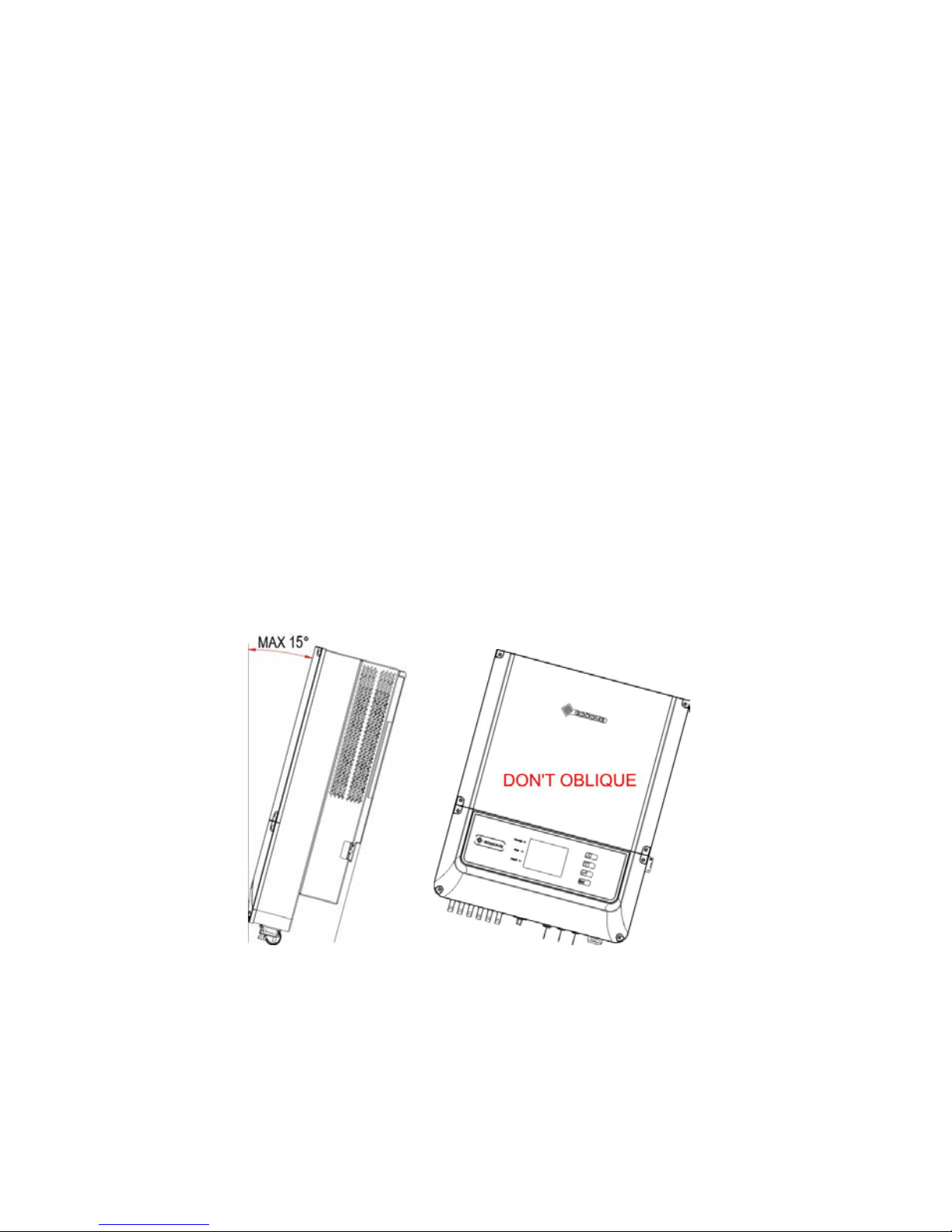
3.1 Mounting Instruction . . . . . . . . . . . . . . . . . . . . . . . . . . 04
3.2 Unpacking . . . . . . . . . . . . . . . . . . . . . . . . . . . . . . . . . 04
3.3 Equipment Installation.. . . . . . . . . . . . . . . . . . . . . . . . . 06
3.4 Electrical Connection.. . . . . . . . . . . . . . . . . . . . . . . . . . 12
3.4.1 Connection to Grid (AC Side Connection) .. . . . . 12
3.4.2 DC Side Connection . . . . . . . . . . . . . . . . . . . . . . 15
3.4.3 RS485 Communication... . . . . . . . . . . . . . . . . . . 18
3.4.4 Wireless Communication. . . . . . . . . . . . . . . . . . 23
3.4.5 USB Communication. . . . . . . . . . . . . . . . . . . . ... 25
3.5 Troubleshooting . . . . . . . . . . . . . . . . . . . . . . . . . . ... . 25
4.System Operation . . . . . . . . . . . . . . . . . . . . . . . . . . . . . . 29
4.1 Functions of Indicating Lights . . . . . . . . . . . . . . . . . . . 29
4.2 LCD Display Functions and Keys Operation . . . . . . . . 30
4.2.1 Top Area – Flow of Power Generated. . . . . . . . . 30
4.2.2 Middle Left – Status Information. . . . . . . . . . . . . 31
4.2.3 Right Middle Area—Histogram Display. . . . . . . . 36
4.2.4 Bottom Area. . . . . . . . . . . . . . . . . . . . . . . . . . . . 38
4.3 Key Operation and LCD Description . . . . . . . . . . . . . . 38
4.3.1 Key Description.. . . . . . . . . . . . . . . . . . . . . . . . . 38
4.3.2 Key Operation and LCD Description. . . . . . . . . . 39
4.4 Menu Introduction. . . . . . . . . . . . . . . . . . . . . . . . . . . . 39
4.5 Usual Start and Operation Display. . . . . . . . . . . . . . . . 40
4.6 Menu Display Description. . . . .. . . . . . . . . . . . . . . . . . 40
4.6.1 Error History Display. . . . . . . . . . . . . . . . . . . . . . 41
4.6.2 Time Setting. . ... . . . . . . . . . . . . . . . . . . . . . . . 41
4.6.3 Language Setting .... . . . . . . . . . . . ... . . . . . . 42
4.6.4 Set the Histogram Display in ‘Year Mode’ .. . . . . 43
4.6.5 Reset Wireless ID . . . . . . . . . . . . . . . ... . . . . . 44
4.7 Error Message. . .. .. . . ... . . . ... . . . ... . . . ... . . . 45
5.Technical Parameters. . . . . . . . . . . . . . . . . . . . . . . . . ... 47

5.1 Temperature Derating Character . . . . . . . . . . . . . . . 49
6.Certificates. . . . . . . . . . . . . . . . . . . . . . . . . . . . . . . . . . . . . 50
7.Maintenance . ... . . . . . . . . . . . . . . . . . . . . . . . . . . . . . . . . 51
7.1 Cleaning the Fans. . . . . . . . . . . . . . . . . . . . . . . . . . 52
7.2 Checking the DC Disconnect. . . . . . . . . . . . . . . . . . 53
8.Warranty . . . . . . . . . . . . . . . . . . . . . . . . . . . . . . . . . . . . . . 54
8.1 Warranty Period. . . . . . . . . . . . . . . . . . . . . . . . . . 54
8.2 Warranty Card. . . . . . . . . . . . . . . . . . . . . . . . . . . . . 54
8.3 Warranty Conditions.. . . . . . . . . . . . . . . . . . . . . ... . 54
8.4 Scope of Warranty. . . . . . . . . . . . . . . . . . . . . . . . . . 54
9.Contact. . . . . . . . . . . . . . . . . . . . . . . . . . . . . . . . . . . . . . . . 56

1/ 56
1. Symbols
Caution! - Failure to observe a warning indicated in this
manual may result in minor or moderate injury.
Danger of high voltage and electric shock!
Danger of hot surface!
Product should not be disposed as normal household waste.
This side up - The package must always be transported,
handled and stored in such a way that the arrows always point
upwards.
Components of the product can be recycled.
Fragile-
The package/product should be handled carefully and
never be tipped over or slung.
Stack Limitation - 6 units of identical packages that may be
stacked in maximum.
Keep Dry – The package/product must be protected from
excessive humidity and must accordingly be stored under
cover.
CE Mark

2/ 56
2. Safety
DT series inverter of Jiangsu GoodWe Power Supply Technology
Co.,Ltd. ( hereinafter referred to as GoodWe ) strictly conforms to
related safety rules in design and test. As electric and electronic
equipment, Safety Regulation shall be followed during installation
and maintenance. Improper operation may bring severe damage to
the operator, the third party and other properties.
The installation and maintenance of the inverters must be performed
by qualified personnel only in compliance with national and local
standards and regulations.
Before installation and maintenance, DC input and AC output of the
inverter should be cut off beforehand and the inverter cannot be
touched within 10 minutes after power cut-off in case of electric
shock.

3/ 56
Partial temperature of the inverter may exceed 60 ℃during
operation, please do not touch in case of scalding.
All electric installation should conform to local electric standard and
permission has to be obtained from local power supply department
before synchronization by qualified personnel.
Children must be kept away from inverters.
Please do not open the front cover of inverter. Apart from wiring
terminal, touching or changing components without authorization
may cause damage to people and inverters. GoodWe may deny the
obligation of warranty service accordingly.
Static electricity may damage electronic components and proper
measures shall be adopted to avoid static electricity.
The output voltage of proposed PV array should be lower than the
inverter maximum rated input voltage; otherwise, GoodWe will not
undertake any obligations and warranty services.
Please switch off the breaker between PV-Inverter and Grid (utility)
firstly before any service. Or else electric hazards will be caused.

4/ 56
3. Installation
3.1. Mounting Instruction
AIn order to achieve optimal performance, the ambient temperature
should be lower than 45 °C.
BFor the convenience of checking the LCD display and possible
maintenance activities, please install the inverter at eye level.
C Inverters should NOT be installed near inflammable and explosive
items. Any electro-magnetic equipment should be kept away from
installation site.
D Product label and warning symbol shall be clear to read after
installation.
3.2. Unpacking
When you receive GoodWe inverter, please check if there is any visible
external damage on the inverter or any accessories. Please also check
if there is anything missing according to the list below.
Inverter……………………………………………………………..……… 1
Wall-mounted Bracket……………………………………………………..1
Positive DC Plug (GW06K-DT)……...….............……...2
Negative DC Plug (GW06K-DT)………………..……..…2
Positive DC Plug (GW10K-DT / GW12K-DT)……...….............……...…4
Negative DC Plug (GW10K-DT / GW12K-DT)………………..……..…..4
Positive DC Plug (GW15K-DT / GW17K-DT)…….............................….6
Negative DC Plug (GW15K-DT / GW17K-DT)………………….…….….6
Unlock Tool for DC Plug…….…………………...………………….......….1

5/ 56
AC Plug………………………………………………………………………1
USB Data Cable……………………………………...……………...……1
Expansion Bolt…………………………………….…………………...…6
Flat Head Screw……………………………………………….....…………1
User Manual………………………………………........................………..1
Warranty Card……………………………………………………..….…..1
Lock Plate……………………...……………………………………..…..….1
Wall-mounted Bracket
Positive DC Plug
Negative DC Plug
Unlock Tool for DC
Plug
AC Plug
USB Data Cable
Expansion Bolt
Flat Head Screw
User Manual
Warranty Card
PV Inverter
Lock Plate

6/ 56
3.3. Equipment Installation
3.3.1 Selecting the installation position
Installation position should be selected based on the following
aspects:
The installation method and mounting location must be suitable for
the inverter's weight and dimensions.
Mount on a solid surface.
Select a well ventilated place sheltered from direct sun radiation.
Install vertically or tilted backward by max 15°. The device cannot
be installed with a sideways tilt. The connection area must point
downwards.
Figure 3.3.1-1

7/ 56
In consideration of heat dissipation and convenient dismantlement,
the minimum clearances around the inverter should be no less than
the following value:
Upward . . . . . . . . . . . . . . . . . . . . . . . . . . . . . . 200mm
Downward . . . . . . . . . . . . . . . . . . . . . . . . . . . . 500mm
Front . . . . . . . . . . . . . . . . . . . . . . . . . . . . . . . . 300mm
Both sides . . . . . . . . . . . . . . . . . . . . . . . . . . . . 500mm

8/ 56
Figure 3.3.1-2
3.3.2 Mounting Procedure
AUse the wall-mounted bracket as a template and drill 6 holes on
the wall, 10 mm in diameter and 80 mm deep.

9/ 56
Figure 3.3.2-1
B Fix the wall mounting bracket on the wall with six expansion bolts
in accessory bag.
C Carry the inverter by holding the four handles shown as below
Figure 3.3.2-2
D Place the inverter on the wall-mounted bracket (as illustrated
below).

10 / 56
Figure 3.3.2-3
Figure 3.3.2-4

11 / 56
EFix the inverter on the wall-mounted bracket with the lock plate in
accessory bag (as illustrated below)
Figure 3.3.2-5
Figure 3.3.2-6
FUse M3*0.5 screw in accessory bag and a padlock to fix the lock
plate on the wall-mounted bracket (as illustrated below)

12 / 56
Figure 3.3.2-7
3.4 Electrical Connection
You must comply with the connection requirement of local regulations.
The inverter is integrate with an RCMU according to VDE0126-1-1/A1.
It monitors residual current from the solar module to grid side of
inverter. The inverter can automatically differentiate between fault
current and normal capacitive leakage currents.
3.4.1 Connection to Grid (AC Side Connection)
ACheck the grid (utility) voltage and frequency at the connection
point of the inverter. It should be phase to phase 400VAC, 50Hz and
three phases.
BCheck the rating of branch circuit breaker. For installing one unit of
6K, 10K or 12K inverter, the recommended breaker rating is
400V/25A. For installing one unit of 15K or 17K inverter, the
Padlock hole ¢5.0

13 / 56
recommended breaker rating is 400V/32A.
CDisconnect the breaker or fuse between PV-Inverter and utility.
D Connect the inverter to the grid as follows:
Switch off the AC Breaker.
Disassemble female connector of the AC wire connector and connect
AC wires to connection socket as indicated.
Figure 3.4.1-1
Insert AC wire to AC socket according to below table and figure.
Caution!
Figure 3.4.1-2
After fastening all screws, reassemble the female connector of the
AC wire connector.
PIN
1
2
3
4
PE
WIRE
Line 1
Neutral
Line 2
Line 3
Ground

14 / 56
Connect the female connector of theAC wire connector to the male
connector on the inverter.
Figure 3.4.1-3
ESpecifications of the AC wires:
AB
C
Figure 3.4.1-4
Depiction Size
A External diameter of the wire 11-20mm
B Sectional area of conducting materials 4~6mm
2
C Length of bare wire Approx.10mm
Remarks: Specifications of AC cables should be type of H05VV-F or
similar.
FAC output connection as Figure 3.4.1-5 shown.

15 / 56
Tighten the 5 pieces of screws
and make sure of their heads
don't exceed the surface
Figure 3.4.1-5
3.4.2 DC Side Connection
AMake sure the maximum open circuit voltage (Voc) of each PV
string does not exceed the inverter input voltage Vmax under any
condition.
BUse Multi-contact connectors for PV array terminals.
C Connect the positive and negative terminals of the PV panel to
corresponding terminals on the Inverter. The DC terminal on each
Inverter can bear 20A DC current.
Female side connector (PV+) Male side connector (PV-)

16 / 56
Both types of connectors must be equipped in pair strictly according to
above graphs.
Strip 7MM length by using wire stripper, and use 4 mm2wire crimpers
with terminals to compress on bare line. To connect red wire with
positive DC terminal, it is ready when you heard ‘crack’; To connect
black wire with negative DC terminal, it is ready when you heard ‘crack’;
To connect the positive, negative DC terminal respectively to inverter’s
positive, negative input terminal, the connector is ready when you
heard ‘crack’.

17 / 56
Figure 3.4.2-1 Separated by Ring Tool
DSpecifications of the DC wires
The cable are used outdoor that must comply with PV cable standards,
as TUV 2Pfg1169, Type PV1-F, 600V, 90℃wet. The wire diameters
should be 2.5-4 mm2.
Remark: The solar energy system often works under harsh
environmental conditions, such as high temperature and ultraviolet
radiation. Therefore, the solar system and photovoltaic array must be
This manual suits for next models
4
Table of contents
Other Jiangsu GoodWe Power Supply Technologu Co. Inverter manuals