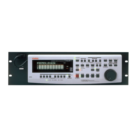
trackit Mk3 User manual

Trackit Mk3
User Manual
Part no. 1114
Issue 2.4
28 February 2018
Created Checked Approved
Digitally signed by Michael
Hulin
Date: 2018.03.02 10:39:47 Z
Digitally signed by David Hulin
DN: cn=David Hulin, o=Lifelines Ltd,
c=GB
Date: 2018.03.02 11:05:11 Z
Digitally signed by Michael
Hulin
Date: 2018.03.02 11:58:46 Z

Trackit Mk3 User Manual
2
Version History
V2.4 (February 2018)
•Added disinfection information in section 2.7.
•Changed N.B. to 0086 (BSI).
V2.3 (May 2014)
•Latest 4th Generation internal Bluetooth details added in Appendix 5
•Bluetooth recording times and range details added
•Latest version low-power XPOD Pulse Oximeter details added in Appendix 2
V2.2 (September 2011)
•Trackit Mk3 introduced: USB Interface detail added to Sections 1.2, 1.3, 3.1, 3.2 and 4.2.
•Large memory cards (FAT32) added in Section 5.6.
•Aux Box 2 added in Appendix 2.
•More Setup parameters added to Appendix 5.
•Quick Setup Guide adjusted in Appendix 6.
•Troubleshooting adjusted in Appendix 8.
V2.1 (June 2010)
•Added Bluetooth indicator to Figure 6
•Added ‘Internal Bluetooth’ paragraph to Appendix 5
•Minor amendments to section 5.7 ‘Reading an ambulatory recording’
•Minor amendments to Appendix 4 ‘Network Connection’
V2.0 (April 2010)
•Reformatted to A4 page size
•Added full documentation to Appendix 4:
oSection 1 Record to PC
oSection 2 Network Connection
oSection 3 Video
•Added full documentation to Appendix 5: Bluetooth Wireless
•Appendix 7: Troubleshooting guide moved to Appendix 8
•Appendix 8: Manufacturer’s Declaration moved to Appendix 9
•Added Appendix 7: Trackit Setup Wizard
V1.8 (28 January 2010)
•Virus protection recommendations added, Page 5.
•Lifelines logo adjusted, Page 3.
•References to Windows 98 and ME removed, Sections 1.4 and 4.
•Check with distributor for later software version added, Section 4.
•Picture of latest main Toolbar updated, Figure 16, and table below updated.
•Picture of main ongoing display window updated, Figure 23.
•Appendix 3 added, Photic and Hyperventilation. Photic refers to separate documentation. Old
Appendix 3 now Appendix 4.
•Appendix 4 added, Trackit Plus and Plus with Video Software. Both refer to separate docu-
mentation. Old Appendix 4 now Appendix 5.
•Appendix 5 added, Bluetooth Wireless. Refer to separate documentation. Old Appendix 5 now
Appendix 6.

Trackit Mk3 User Manual
3
Trackit manufactured by:
Lifelines Ltd, 7 Clarendon Court,
Over Wallop, near Stockbridge,
Hampshire SO20 8HU, UK
Telephone +44 (0)1264 782226
www.LLines.com
sales@LLines.com
0086

Trackit Mk3 User Manual
4
Disclaimers & Warranties
The information in this section is subject to change without notice.
Except as stated below, Lifelines Ltd makes no warranty of any kind with regard to this material,
including, but not limited to, the implied warranties of merchantability and fitness for a particular
purpose. Lifelines shall not be liable for errors contained herein or for incidental or consequential
damages in connection with the furnishing, performance or use of this material.
Lifelines shall warrant its products against all defects in material and workmanship for one year
from the date of delivery.
Misuse, accident, modification, unsuitable physical or operating environment, improper mainte-
nance or damage caused by a product for which Lifelines is not responsible will void the warranty.
Lifelines do not warrant uninterrupted or error-free operation of its products.
Lifelines or its authorised agents will repair or replace any products that prove to be defective dur-
ing the warranty period, provided that these products are used as prescribed in the operating in-
structions in the user’s and service manuals.
No other party is authorised to make any warranty to assume liability for Lifelines products. Life-
lines will not recognise any other warranty, either implied or in writing. In addition, services per-
formed by someone other than Lifelines or its authorised agents or any technical modification or
changes of products without Lifelines prior, written consent may be cause for voiding this warranty.
Defective products or parts must be returned to Lifelines or its authorised agents, along with an
explanation of the failure. Shipping costs must be prepaid.
Lifelines Ltd. manufactures hardware and software to be used on or with standard PC-compatible
computers and operating software. Lifelines, however, assumes no responsibility for the use or reli-
ability of its software or hardware with equipment that is not furnished by third-party manufactur-
ers accepted by Lifelines at the date of purchase.
All warranties for third-party products used within the Trackit system are the responsibility of the
relevant manufacturer. Please refer to the relevant documentation on each product for further de-
tails.
This document contains proprietary information that is protected by copyright. All rights are re-
served. No part of this document may be photocopied, reproduced in any other form or translated
into another language without the prior written consent of Lifelines.
Trademarks
Microsoft, Windows and Windows NT are registered trademarks of the Microsoft Corporation. All
other trademarks and product names are the property of their relevant owners.
Responsibility of manufacturer
The manufacturer and distributor consider themselves responsible for the equipment’s safety, relia-
bility and performance only if:
any peripheral equipment to be used with Trackit is supplied by third-party providers recom-
mended by the manufacturer;
assembly operations, extensions, readjustments, modifications, or repairs are carried out by
persons authorised by the manufacturer;
the electrical installation of the relevant room complies with the appropriate requirements;
the equipment is used by a health-care professional and in accordance with the instructions for
use.
Note: the manufacturer has a policy of continual product improvement; hence the equipment
specifications are subject to change without notice.
Check with Lifelines or your distributor if a software update is available.

Trackit Mk3 User Manual
5
Note: Medical electrical equipment needs special precautions regarding EMC and needs to be in-
stalled and put into service according to the EMC information provided in the Appendix.
Software and Virus Protection
Lifelines takes all reasonable steps to ensure that it’s software is virus-free. In line with modern
computing practice, it is advisable that continual protection against viruses, trojans, malware, ad-
ware etc. is provided on the PC used for installation and the surrounding systems. Please note the
following recommendations which should be supported by your internal IT/Computing department
procedures and practices:
1.Virus protection software should be installed on every computer at risk of infection. This soft-
ware should have a resident (online) shield and provide email scanning if appropriate.
2.Virus scanning should be set to manual mode or automatic if desired but at a time when the
system is not being used.
3.All programs offering auto-update features, including Windows, should be set to manual or
automatic if desired but at a time when the system is not being used.
4.Adopt formal departmental or organisational procedures to ensure the integrity and safe op-
eration of the medical equipment and supporting systems.

Trackit Mk3 User Manual
6
Contents
Version History 2
Disclaimers & Warranties 4
Trademarks 4
Responsibility of manufacturer 4
Software and Virus Protection 5
Contents 6
Illustrations 8
1System Overview 10
1.1 General description 10
1.2 Cautions and Warnings 10
1.3 Explanation of symbols 11
1.4 The system and its parts 12
1.5 Specifications and safety 12
Description of the components 13
2Installation and Maintenance 15
2.1 Checks for completeness and integrity 15
2.2 Environmental parameters for operation 15
2.3 Use in the home environment 15
2.4 Power supply connections 15
2.5 Use with other equipment 16
2.6 Interference 16
2.7 Maintenance and cleaning 16
2.8 Disposal of equipment 16
3Connections for Trackit Mk3 setup 17
3.1 Overview 17
3.2 Connecting the Trackit Mk3 18
3.3 Switching on 18
3.4 Warning symbols on the display 19
4The setup software 20
4.1 Setting up a recording protocol 20
4.2 Configuring the recorder 25
4.3 Montage Editor 31
5The ambulatory recording 33
5.1 Changing batteries and cards 33
5.2 Fitting the Clickon PCU 37
5.3 Event marking 38
5.4 Ending a recording 38
5.5 Identifying a recording 39
5.6 Advanced Settings 39
5.7 Reading an ambulatory recording 43
Appendix 1: Trackit Mk3 Specifications 44
EEG inputs 44
Polygraphy inputs 44
Aux. high-level DC Inputs 45
Modes of operation 45
Connections, ports and controls 45
Back-light display 45
Recording format 45
Physical characteristics 45
Safety and EMC standards 46

Trackit Mk3 User Manual
7
Appendix 2: Trackit Mk3 options 47
Nonin XPOD pulse oximeter 47
Appendix 3: Photic Stimulator and Hyperventilation 50
Photic Stimulation 50
Hyperventilation 51
Appendix 4: Record to PC and Synchronised Video 53
1Record to PC 53
2Network Connection 53
3Video 57
Appendix 5: Bluetooth Wireless 61
Introduction 61
System overview 62
Connection and use 63
Application PC Setup 66
Trackit and Bluetooth Module Setup 69
Trackit Bluetooth Module Specifications 78
Parameter Data 78
Regulatory 79
FCC Statement 80
IC Compliance 80
Guidelines for Efficient and Safe Use 81
Trackit Bluetooth Battery Power Consumption 83
Bluetooth Range 83
Bluetooth Knowledge Base 85
Appendix 6: Trackit quick setup and operation guide 86
Appendix 7: Trackit Setup Wizard 87
Appendix 8: Troubleshooting guide 88
COM port problems with Bluetooth communication to Trackit Mk3 88
Problems starting the recording 88
File review problems 89
Appendix 9: Manufacturer’s Declaration 90
EMC Compatibility 90

Trackit Mk3 User Manual
8
Illustrations
Figure 1 Connecting the Trackit Mk3 for recorder set-up 17
Figure 2 Connecting to the Trackit Mk3 recorder 18
Figure 3 Trackit Mk3 recorder: front panel 19
Figure 4 The Trackit Mk3 display 19
Figure 5 New Patient dialog 20
Figure 6 New Patient database 21
Figure 7 Signal list 21
Figure 8 Signal editing tool 22
Figure 9 EEG setup 22
Figure 10 Setup Recording dialog 23
Figure 11 View Hookup 23
Figure 12 Channel setup 24
Figure 13 Recording Channel editing 25
Figure 14 Trackit software toolbar 25
Figure 15 Trackit Control Panel 26
Figure 16 Trackit status 'B' 27
Figure 17 Recording Control 27
Figure 18 Ongoing trace display 29
Figure 19 Adjust display parameters 30
Figure 20 Impedance check 30
Figure 21 The online event viewer 31
Figure 22 Montage Editor 32
Figure 23 Opening the rear battery box/door 33
Figure 24 Removing and replacing PP3 batteries 34
Figure 25 Removing and replacing Lithium rechargeable battery 34
Figure 26 Closing the rear Battery box/door 35
Figure 27 Removing and replacing the flash card 36
Figure 28 Removing the flash card 36
Figure 29 Clickon PCU Retaining screw location 37
Figure 30 Detach the PCU 37
Figure 31 Lift the PCU away from the Trackit Mk3 38
Figure 32 Locating the PCU 38
Figure 33 Trackit Defaults Tab 1 40
Figure 34 Trackit Defaults | Tab 2 41
Figure 35 Pulse oximeter and oximeter probe 47
Figure 36 Connecting the oximeter to Trackit Mk3 48
Figure 37 Connecting the oximeter to the oximeter probe 48
Figure 38 Attaching the oximeter probe to the finger 48
Figure 39 Display of SaO2 49
Figure 40 Photic Stimulation 50
Figure 41 Photic Stimulation control window 50
Figure 42 Photic trigger signal definition 51
Figure 43 Hyperventilation 51
Figure 44 Hyperventilation control window 52
Figure 45 Trackit video preview 59
Figure 46 Trackit Mk3 with Internal Bluetooth Module 62
Figure 47 The Trackit Control Panel 63
Figure 48 A typical Bluetooth Places view 64
Figure 49 Trackit Main Screen 65
Figure 50 Options Tab 1 66
Figure 51 Options Tab 2 67
Figure 52 Trackit Defaults Tab1 69
Figure 53 Trackit Defaults Tab2 70
Figure 54 Trackit Defaults Tab 3 70
Figure 55 Trackit Defaults Tab 4 72

Trackit Mk3 User Manual
9
Figure 56 Trackit Defaults | Bluetooth Setup Tab 1 (General) 73
Figure 57 Trackit Defaults | Bluetooth Setup Tab 2 (Profile) 74
Figure 58 Trackit Defaults | Bluetooth Setup Tab 3 (Serial) 75
Figure 59 Trackit Defaults | Bluetooth Setup Tab 4 (Version) 76
Figure 60 Trackit Defaults | Bluetooth Setup Tab 5 (Misc) 76
Figure 61 Trackit Defaults | Bluetooth Setup Tab 6 (Pairing) 77

Trackit Mk3 User Manual
10
1System Overview
1.1 General description
Intended use
The Trackit Mk3 is intended to measure and record EEG signals.
Indications for use
The Trackit Mk3 is used as an aid in the diagnosis of neurophysiological disorders such as epilepsy.
General description
The Trackit Mk3 is a multi-channel, ambulatory, electroencephalograph recorder. It is a compact
body-worn device that is battery powered and the data is stored on a Compact Flash card.
The device is suitable for use in a clinical environment and in an outpatient setting. The EEG
electrodes are fitted to the patient by a trained clinician prior to the patient being sent home. No
subsequent intervention is required by the patient.
Upon completion of the recording, the data which is stored on a Compact Flash card is reviewed by
a clinician using review and analysis software on a PC.
This device is intended only as an adjunct device in patient assessment; it must be used in
conjunction with other methods of patient diagnosis.
The device does not sustain or support life.
Intended User
The intended user of the device is a healthcare professional who has the training and knowledge to
undertake EEG examinations and is familiar with EEG equipment and practice.
1.2 Cautions and Warnings
CONTRAINDICATIONS: Do not use the Trackit Mk3 in an MRI environment, in an explosive
atmosphere or during defibrillation.
WARNING: This device is intended to be used by a healthcare professional and in accordance with
these instructions for use which must be read in their entirety before the device is used.
WARNING: This device in intended only as an adjunct device in patient assessment; it must be
used in conjunction with other methods of patient diagnosis.
WARNING: Lifelines does not supply EEG electrodes. The unit accepts standard 1.5 mm
touchproof electrodes using DIN 42802-style connectors. To ensure patient safety, the electrodes
used must be approved to the Medical Device Directive 93/42/EEC in Europe or to the relevant
local standards outside Europe.
CAUTION: The conductive part of electrodes and their connectors, including the Neutral electrode,
should not contact other conductive parts including earth.
WARNING: Lifelines does not supply the Nonin sensor. Only use the ‘PureLight’ sensors specified
by Nonin to be used with their Oximeters.
WARNING: Strangulation hazard due to long cables. As with all medical equipment, carefully
route patient cabling to reduce the possibility of patient entanglement or strangulation.
CAUTION: When in close proximity to the recorder, do not use mobile phones, transmitters, power
transformers, motors, or other equipment that generates magnetic fields. Refer to the Appendix for
more information. Medical electrical equipment needs special precautions regarding EMC and needs
to be installed and put into service according to the EMC information provided in the Appendix.
WARNING: The function or safety of the equipment could be impaired if it has been subjected to
unfavourable conditions in storage or in transit. If at any time function or safety is thought to be
impaired, the instrument should be taken out of operation and secured against unintended use.
WARNING: Do not open the equipment.
WARNING: Do not modify this equipment without the authorization of the manufacturer.

Trackit Mk3 User Manual
11
1.3 Explanation of symbols
Type BF equipment Follow operating instructions
Input/output connection Input connection
Special recycling required, do not dispose of in landfill. When this equipment has
reached the end of its useful life, it must be disposed of in an environmentally-
friendly way. Waste electrical and electronic equipment (WEEE) requires special
procedures for recycling or disposal. This includes batteries, printed circuit boards,
electronic components, wiring and other elements of electronic devices. Follow all
of your respective local laws and regulations for the proper disposal of such
equipment. Contact your local distributor for information concerning this.
Consult warnings in User Manual Bluetooth
Push to eject Compact Flash card Manufacturer
Storage and transport symbols
Temperature limits Fragile
Keep dry Relative humidity limits
Barometric pressure limits
International protection code
Protected against ingress of solid object 12.5 mm diameter.
Protected against access to hazardous parts with finger.
Protected against ingress of water dripping (15° tilted).
-10
+50
°C
10
95
%RH
500
1060
hPa
IP22

Trackit Mk3 User Manual
12
1.4 The system and its parts
The Trackit Mk3 recorder is a multi-channel1ambulatory electroencephalograph designed for use in
a variety of monitoring applications, including those concerned with neurological and sleep disor-
ders.
Note 1: Trackit Mk3 is available in a number of versions, including a 32-channel (Trackit-32/0 or
Trackit-24/8), a 24-channel (Trackit 24/0) and a 12-channel (Trackit-24/0). The version is dis-
played on the Trackit Mk3 LCD at switch-on. This manual applies to all versions, the only difference
being the number of channels.
The Trackit Mk3 recorder comprises the following components:
Recorder
Trackit-32/0 (32 EEG) part number 1186
Trackit-24/0 (24 EEG) part number 1187
Trackit-12/0 (12 EEG) part number 1189
Trackit-20/4 (20 EEG, 4 POLYGRAPHIC) part number 1184
Trackit-18/8 (18 EEG, 8 POLYGRAPHIC) part number 1185
Trackit-24/8 (24 EEG, 8 POLYGRAPHIC) part number 1188
Recorder with internally fitted wireless Bluetooth option
Trackit-32/0 (32 EEG) part number 1171
Trackit-24/0 (24 EEG) part number 1172
Trackit-12/0 (12 EEG) part number 1174
Trackit-20/4 (20 EEG, 4 POLYGRAPHIC) part number 1169
Trackit-18/8 (18 EEG, 8 POLYGRAPHIC) part number 1170
Trackit-24/8 (24 EEG, 8 POLYGRAPHIC) part number 1173
Patient connection unit (PCU) Clickon
PCU-clickon Short part number 1181
Patient connection unit (PCU) Cabled
PCU-cabled 24/0 part number 1104
PCU-cabled-Extended 32/0 (universal) part number 1136
Cable, PCU 32ch 1m part number 1106
Cable, PCU 32ch 0.5m part number 1105
Cable, USB 3m part number 1277
Trackit Mk3 strap, adult part number 1117
Trackit Mk3 strap, child part number 1118
Trackit Mk3 bag with PCU-clickon part number 1259
Trackit Mk3 set up software part number 1009
Trackit Mk3 User Manual part number 1114
Battery Box PP3 part number 1111
Battery Box PP3-Small part number 1140
Battery Box Li part number 1112
1.5 Specifications and safety
Refer to Appendix 1 for specifications.
The system has been certified and complies with the following standards:
EN60601-1 and
EN60601-2-26
European standard for medical electrical equipment, general re-
quirements and EEG systems.
UL60601-1:2003 USA standard for medical electrical equipment, general require-
ments.
CAN/CSA 22.2 No 601.1 M90 Canadian standard for medical electrical equipment, general re-
quirements.
EN60601-1-2:2001 European standard for medical electrical equipment, EMC require-
ments, calling:
EN55011
Conducted Emissions, Group 1, Class B
EN55011
Radiated Emissions, Group 1, Class B
EN61000-4-2
Electrostatic Discharges

Trackit Mk3 User Manual
13
EN61000-4-3
Immunity - Radiated RF Field
EN61000-4-4
Immunity - Transients Bursts
EN61000-4-5
Immunity – Surges
EN61000-4-6
Immunity – Conducted
EN61000-4-8
Immunity – Power frequency fields
EN61000-4-11
Immunity – Voltage dips, interruptions
EN61000-3-2
Harmonic Emissions
EN61000-3-3
Voltage Fluctuations/flicker
Degree of protection against electrical shock (when con-
nected to host system) Type BF
Type of protection against electrical shock (when con-
nected to host system) Internally powered
or Mains powered Class 1 or 2 (Mk2)
or USB powered (Mk3)
Degree of protection against harmful ingress
of water
Ordinary (no protection)
Mode of operation
Continuous
Degree of safety of application in the presence of a
flammable anaesthetic mixture with air or with oxygen
or nitrous oxide
Not suitable
Description of the components
The Trackit Mk3 recorder
The Trackit Mk3 is a multi-channel recording device designed for use in recording a patient’s EEG
signals. It comprises a 24-channel EEG (monopolar) amplifier acquisition board, an 8-channel poly-
graphic acquisition board and control board with all the I/O interface for serial and patient commu-
nication. When connected to a host PC, the device has built-in isolation for patient safety. The de-
vice may be powered either by its own batteries or a PC USB port. EEG data is stored on an inter-
nal CF card. The data format is native European Data Format (EDF), allowing the EEG files to be
reviewed by any EDF-compatible EEG reader.
Patient Connection Unit
The Patient Connection Unit (PCU) connects the standard 1.5mm touchproof EEG recording elec-
trodes attached to the patient to the Trackit Mk3 unit. It is available either as a ‘Cabled’ type which
is connected via a screened cable or a ‘Clickon’ type which fits on the Trackit Mk3 directly without
needing a cable.
WARNING: Lifelines does not supply EEG electrodes. The PCU accepts standard 1.5 mm
touchproof electrodes using DIN 42802-style connectors. To ensure patient safety, the
electrodes used must be approved to the Medical Device Directive 93/42/EEC in Europe
or to the relevant local standards outside Europe.
CAUTION: The conductive part of electrodes and their connectors, including the Neutral
electrode, should not contact other conductive parts including earth.
PC Connection Cable
The Trackit Mk3 plugs directly into a USB port on the PC.
Batteries
3 PP3 disposable alkaline batteries are optionally supplied with the Trackit Mk3 recorder. Alterna-
tively, a rechargeable Lithium battery option is available and a small (single) PP3 option.
CF flash card
A Compact Flash (‘CF’) card is used to store the EEG data recorded by Trackit Mk3. Storage cards
of varying capacity are available in the CF format.

Trackit Mk3 User Manual
14
Trackit setup software
The Trackit setup software runs under Microsoft Windows 2000 (with SP2), Windows XP, Windows
Vista or Windows 7 on the host PC and is used to setup and review the Trackit Mk3 recorder for an
ambulatory recording session.
The Trackit Mk3 recorder is connected to the PC via the connection cable or wirelessly with Blue-
tooth. The recording setup/montage, and patient information/ID is downloaded to the device, and a
short review is made to verify that all the electrodes have been attached correctly.
The recorder is then disconnected from the PC and the ambulatory recording is started.
Functions of the setup software:
Download the recording template. This includes:
which electrodes are turned on or off;
the recording montage;
any timed recording modes.
Download the unique patient identifier onto the card so that no confusion can arise as to whom
the recording belongs to.
Perform a calibration of the Trackit Mk3 device
Synchronise the Trackit Mk3 time and date to that of the host.
Perform a routine EEG recording prior to the patient’s ambulatory EEG recording.
What does a recording consist of?
2–36 channels of recorded EEG/polygraphic signals
Signals recorded over a period usually not less than 24 hours
Patient event markers correlated in time with the real time clock displayed on Trackit Mk3 LCD
display
Data and results stored to card for future evaluation
Data review post-recording using any compatible EDF review program

Trackit Mk3 User Manual
15
2Installation and Maintenance
WARNING: The following section must be read and understood before the equipment is
switched ON.
Note: Medical electrical equipment needs special precautions regarding EMC and needs to be in-
stalled and put into service according to the EMC information provided in the Appendix.
The function or safety of the equipment could be impaired if it has been subjected to unfavourable
conditions in storage or in transit. If at any time function or safety is thought to be impaired, the
instrument should be taken out of operation and secured against unintended use.
The manufacturer should be contacted (details on page 3) for assistance, if needed, in setting up,
using or maintaining the equipment; or to report unexpected operation or events.
2.1 Checks for completeness and integrity
1 Remove the equipment from the packaging case(s).
2 Use the parts list to check that all ordered items have been received.
3 Assembly instructions for third-party products will be found in their packing cases. It is recom-
mended that these instructions be filed with Trackit Mk3 technical reference materials.
4 Check for signs of damage that may have occurred during transit or storage. If any damage is
found, do not use the instrument; contact your distributor.
2.2 Environmental parameters for operation
Operation
The instrument is designed to operate within the following ranges:
Temperature +10°C to +40°C
Relative humidity 25% to 95% non-condensing
Atmospheric pressure 700mB to 1060mB
Do not obstruct any cooling slots.
Position the instrument so that air flows freely.
Storage and transport
When the instrument is in store or being transported, the following ranges are tolerated:
Temperature -10°C to +50°C
Relative humidity 10% to 95% non-condensing
Atmospheric pressure 500mB to 1060mB
2.3 Use in the home environment
The equipment is intended to be operated in its bag where it is protected against ingress of solid
objects and water to a degree of IP22.
Keep the equipment away from sources of heat.
Do not use mobile phones.
Do not allow pets or children to interfere with the sensor cables.
2.4 Power supply connections
Power requirements
Standard PC USB port or 9V PP3 batteries when operating independently.
No protective earth required.
Power consumption
Maximum power from USB port: 2.5W
Leakage current
This instrument is designed to comply with IEC 601-1, the international standard for medical elec-
tronic equipment, which specifies the permissible levels of leakage current from individual prod-
ucts. A potential hazard exists in the summation of leakage currents caused by connecting several
pieces of equipment together. Because this instrument can be used in conjunction with standard
electronic devices, the total leakage current should be tested at regular intervals.

Trackit Mk3 User Manual
16
2.5 Use with other equipment
Defibrillators and HF surgical equipment
The equipment is not defibrillator proof and should not be used in situations where a defibrillator is
likely to be used.
The equipment should not be used with high frequency surgical equipment.
Other patient-connected equipment
When used simultaneously with other patient-connected equipment, for example a cardiac pace-
maker or other electrical stimulator, it is unlikely that a safety hazard will arise. However always
consult the documentation supplied with the other patient-connected equipment to ensure that all
hazards, warnings and cautions are considered before the equipment is used together.
2.6 Interference
Trackit Mk3 will continue to operate in the presence of radio frequency magnetic fields (RF) and the
effects of electrostatic discharges (ESD) and other interference, in accordance with the require-
ments of EN60601-1-2. However, Trackit Mk3 records signals of very low amplitude, and these sig-
nals themselves are not immune to the effects of RF, ESD and low-frequency magnetic field inter-
ference. Such interference may cause signal artefacts.
Caution: when in close proximity to the recorder, do not use mobile phones, transmit-
ters, power transformers, motors, or other equipment that generates magnetic fields.
Refer to the Appendix for more information.
Note: Medical electrical equipment needs special precautions regarding EMC and needs to be in-
stalled and put into service according to the EMC information provided in the Appendix.
2.7 Maintenance and cleaning
The Trackit Mk3 contains no user-serviceable parts (apart from replaceable batteries). The system
uses solid-state components and requires no routine testing or maintenance procedures apart from
occasional cleaning and checking for wear and damage to all parts including the accessories.
All the outer surfaces of the individual pieces of equipment of the Trackit system may be cleaned
using a soft cloth moistened with water and a mild detergent. Each item may also be cleaned using
a low-pressure air-line or a vacuum cleaner.
Disinfection of the equipment can be carried out by the use of QAC-based disinfectants. Wipes are
recommended in order to prevent the ingress of any liquid into the equipment. Suitable products
include Mikrozid Sensitive Wipes (Schülke & Mayr GmbH), Microbac forte (Paul Hartmann AG), Dis-
tel Wipes (Tristel Ltd.).
Caution: Do not allow any liquid to enter the case of any instrument or connector.
Do not use acetone on any of the instruments.
2.8 Disposal of equipment
The expected service life of the equipment is five years. When it has reached the end of its operat-
ing life, it should be disposed of in accordance with local waste regulation authority that is typically
within the local government office.
Caution: do not dispose of batteries by incineration.

Trackit Mk3 User Manual
17
3Connections for Trackit Mk3 setup
3.1 Overview
Below is an overview diagram showing the principal components when connected to a PC during
system set up.
Figure 1 Connecting the Trackit Mk3 for recorder set-up
List of parts supplied by Lifelines:
Trackit Mk3 recorder plus bag
Patient Connection Unit (PCU), for electrode connection
1 x CF flash card (optional)
3 x PP3 batteries (optional)
PC USB cables
List of optional parts supplied by third parties:
Host PC/laptop with power cable
CF cards
Batteries
Battery charger

Trackit Mk3 User Manual
18
3.2 Connecting the Trackit Mk3
The Trackit Mk3 is simply plugged into the PC USB port using the cable supplied. Note: only use
the USB cable part number 1277 (with the red tip) for the Trackit Mk3 as shown below:
Figure 2 Connecting to the Trackit Mk3 recorder
The necessary USB drivers will be found on the installation CD. Upon first connection of the Trackit
Mk3 to the PC USB port, at the Windows prompt, browse to the folder CD Drive:\USB Drivers. From
there, Windows will find the correct drivers for the version of Windows being used.
3.3 Switching on
Turn on the unit by pressing the button on the right of the LCD display on the front panel of the re-
corder.
Trackit
RJ45 Connection

Trackit Mk3 User Manual
19
Figure 3 Trackit Mk3 recorder: front panel
After several seconds the LCD display indicates that Trackit Mk3 is performing a self-test for sys-
tem integrity. On completion of the self-test the LCD indicates the status of the Trackit Mk3 re-
corder.
Indicators
The following indicators are available depending on Trackit Mk3 status:
Û~11:49 Û~00:00
Û~71 %âÛ Û~2049M
Figure 4 The Trackit Mk3 display
Key:
1 Time of day
2 Recording time
3 Battery capacity remaining
4 Internal Bluetooth on/off
5 Rear door open warning
6 CF Card capacity remaining
Time of day The battery-backed, real time clock which is synchronized
to the host during setup.
Recording time of this recording
If not recording, ‘00:00’ is displayed.
Disk capacity Remaining storage capacity in MB. If there is no card pre-
sent, ‘0’ is displayed.
Battery capacity Approximate battery capacity remaining (as % of full bat-
tery capacity).
Rear-door open warning symbol
Flashes when the rear battery door is open.
Internal beeper
Warning of low battery or rear-door open.
3.4 Warning symbols on the display
Low card capacity Symbol L accompanied by beeping every 30 seconds.
Special recording mode
Timed or sampled recordings are indicated by the symbol
S.
Recording to card
The symbol R next to card capacity.
Internal Bluetooth on/off When the Internal Bluetooth option is fitted to the Trackit
Mk3, the unit will display whether it is enabled or disabled
with a large ‘B’ (enabled) or small ‘β’ (disabled) next to
the ‘%’ indication. To toggle the current selection the
pushbutton is pressed 5 times within 3 seconds. The dis-
play will change to indicate the new state.
Refer to Appendix 5 for further information on Bluetooth.
2
1
4 5
3
6

Trackit Mk3 User Manual
20
4The setup software
The setup software is available on CD. A readme file describes installation. Check with your distrib-
utor or Lifelines if a newer version of software is available.
Trackit setup software is supported on Microsoft Windows 2000 (with SP2), Windows XP, Windows
Vista and Windows 7.
When Trackit Mk3 is connected to the host PC, the software allows the user to define parameters
for the recording, such as recording montage, start time and stop time, mode of recording etc.
The setup software has the following functions:
Define signal types: create labels to attach to inputs
Attach the desired signal type (label) to the recording input. For example, input 1 with a signal
type FP1
Create a recording montage and download it to the recorder
Perform a calibration of the inputs
View signals online and adjust display parameters such as chart speed and display sensitivity
Start and stop a Trackit recording session
4.1 Setting up a recording protocol
Summary
Step 1 Define the patient ID
Step 2 Define the signals
Step 3 Define the inputs
Step 4 Define the recording channels
Step 5 Activate the recording control
Step 6 Connect the Trackit Mk3 for setup
Step 7 Check Trackit Mk3 status
Step 8 Start a recording
Step 9 View the ongoing EEG traces
Step 1 Define the patient ID
1 Select the New patient icon on the toolbar.
New Patient icon
2 Enter the patent name and Recording ID into the New Patient di-
alog.
This information is saved with the recording setup for download
to the recorder in a future recording.
It is possible to configure the system to use a patient database (Figure 6) instead of the simple di-
alog shown above.
Figure 5 New Patient dia-
log
Table of contents
