Trackunit TU600-x Supplement

NOTE: Model ID TU600-x (LTE Cat M1 /Cat NB1 / 2G)
Short guide : TU600-x
Version
0
.
3
,
January 2020
45,5 mm (W)
17,9
mm (
H
)
122,3 mm (L)

TU600-x
Short uide TU600-x v0.2, January 2020, ©Trackunit 2020 2
Index
Practical Advice .......................................................................................... 3
Machine and vehicle guidelines for correct wiring ....................................... 4
Installation example .................................................................................... 5
Functionality check: LED on the unit ........................................................... 6
Installation check and update using “Verify my Trackunit” .......................... 7
Input filtering (INFILT) ................................................................................. 8
CAN bus termination resistor ...................................................................... 9
Troubleshooting ........................................................................................ 10
Product specifications ............................................................................... 11
Temperature range ................................................................................... 12
Mechanical specifications ......................................................................... 12
Regulatory information and precautions.................................................... 13
Approvals and Certifications ..................................................................... 15

TU600-x
Short uide TU600-x v0.2, January 2020, ©Trackunit 2020
3
Practical Advice
1. Save important number
2. In tallation i be t done out ide
3. Correct po itioning of the unit
The serial number is
located on the unit.
The mobile number
and unit serial number
are located on the box
label. It can be peeled
off and saved for later
use.
Do not perform
installation inside a
building.
Install the unit outside
for better PS and
SM/UMTS signal.
Position the unit as
shown for optimal
signal conditions.
Avoid installing the unit
directly under a layer of
metal or next to wires.
S/N xxxxxx

TU600-x
Short uide TU600-x v0.2, January 2020, ©Trackunit 2020 4
Machine and vehicle guideline for correct wiring
Wire color
Description
Power Connect to machine battery through a fuse (mandatory)1
round Connect to ground (mandatory)
Digital input 1 Can be connected to hour counter. Optional input2
Digital input 2 Connect to the ignition signal (mandatory for vehicles and machines)1
Digital input 3 Optional input1
Digital input 4 Can be used for INFILT function. Optional input2
Digital output 1 Can be used to control a relay3/4
CAN High Connect to CAN High
CAN Low Connect to CAN Low
1 – Wire input M8 connector for access control and temperature sensor
1: Supply voltage range 12–48V
2: Active/high when min. 9,5V DC at input
3: Max. load 200 mA
4: Do NOT use this output to switch off vehicles and machines during operation or driving

TU600-x
Short uide TU600-x v0.2, January 2020, ©Trackunit 2020 5
In tallation example

TU600-x
Short uide TU600-x v0.2, January 2020, ©Trackunit 2020 6
Functionality check: LED on the unit
Status
LED mode
LED color
Status indication
Red flashing light and constant
green light in LED
- Mobile network is OK and PS
has valid satellite position
!
No light in LED
- No power supply
!
Constant red light and no green
light in LED
- Power supply is OK, but NO mobile network
- PS has NO satellite position
!
Red flashing light and no green
light in LED
- Mobile network is OK
- PS has NO satellite position
!
Constant red and green light in
LED
- Power supply is OK, but NO mobile network
- PS has valid satellite position
LED
LED

TU600-x
Short uide TU600-x v0.2, January 2020, ©Trackunit 2020 7
In tallation check and update u ing
“Verify my Trackunit”
Step 1: Login
- o to
http://verify.trackunit.com
- Enter user name and
password
Step 2: Find unit
- Enter serial number and
then click “Find”
Step 3: Review
status
- Time of last received data
- PS and mobile signal
- Mobile number
- Power supply voltage
- Internal battery voltage
- Status of inputs 1-4
(on/off)
- Click “Find” again to
refresh status
Step 4: Basic
configuration
options
- Enter a device name
- Enter engine hours
- Enter start distance
- Select category
- Connect up to multiple
groups
- Add a note (visible in
Trackunit Manager)
Step 5: Logout
- Click “Update” to save
- Click “Logout”
Note
- Prior to verification, make
sure the unit is installed
and active in an area with
sufficient PS and mobile
coverage.

TU600-x
Short uide TU600-x v0.2, January 2020, ©Trackunit 2020 8
Input filtering (INFILT)
In case the main breaker is on the negative
wire (ground wire from the machine battery),
the inputs may register a voltage level and
start counting operating hours.
To avoid this situation, the digital input 4
(pink wire) should be connected to the
chassis/ground on the machine.
The infilt function should be activated via
“Verify my Trackunit”
Activation of input filtering
o to: http://verify.trackunit.com/
NB! Enabling the filtering function will
disable inputs 1 to 3 when input 4 is
on/active. This can prevent all digital input
alarms. It will also disable the use of any
alarm function on digital input 4.

TU600-x
Short uide TU600-x v0.2, January 2020, ©Trackunit 2020 9
CAN bu termination re i tor
When installing the TU600 on a J1939 CAN-bus, it is very important to determine if the
installation is on a “private” CAN-bus directly to the CAN controller, or if the TU600 is to be
installed as a stub on a CAN-bus with multiple CAN devices already attached.
Default etup without 120-ohm bu termination.
The 120-ohm termination resister is a software-controlled resistor, so make sure to use and
select the correct TU600 CAN-bus profile.
CAN-bu profile i elected in Trackunit Manager and oftware control the re i tor etup.
With 120-ohm bu termination (directly connected)
Without 120-ohm bu termination ( tub connected)
NB! When the unit is stub connected, the wire length must be minimized to avoid CAN-bus noise and
error ratio.

TU600-x
Short uide TU600-x v0.2, January 2020, ©Trackunit 2020 10
Trouble hooting
Error description
Possible solutions
No reply on SMS command
Verify correct SM number
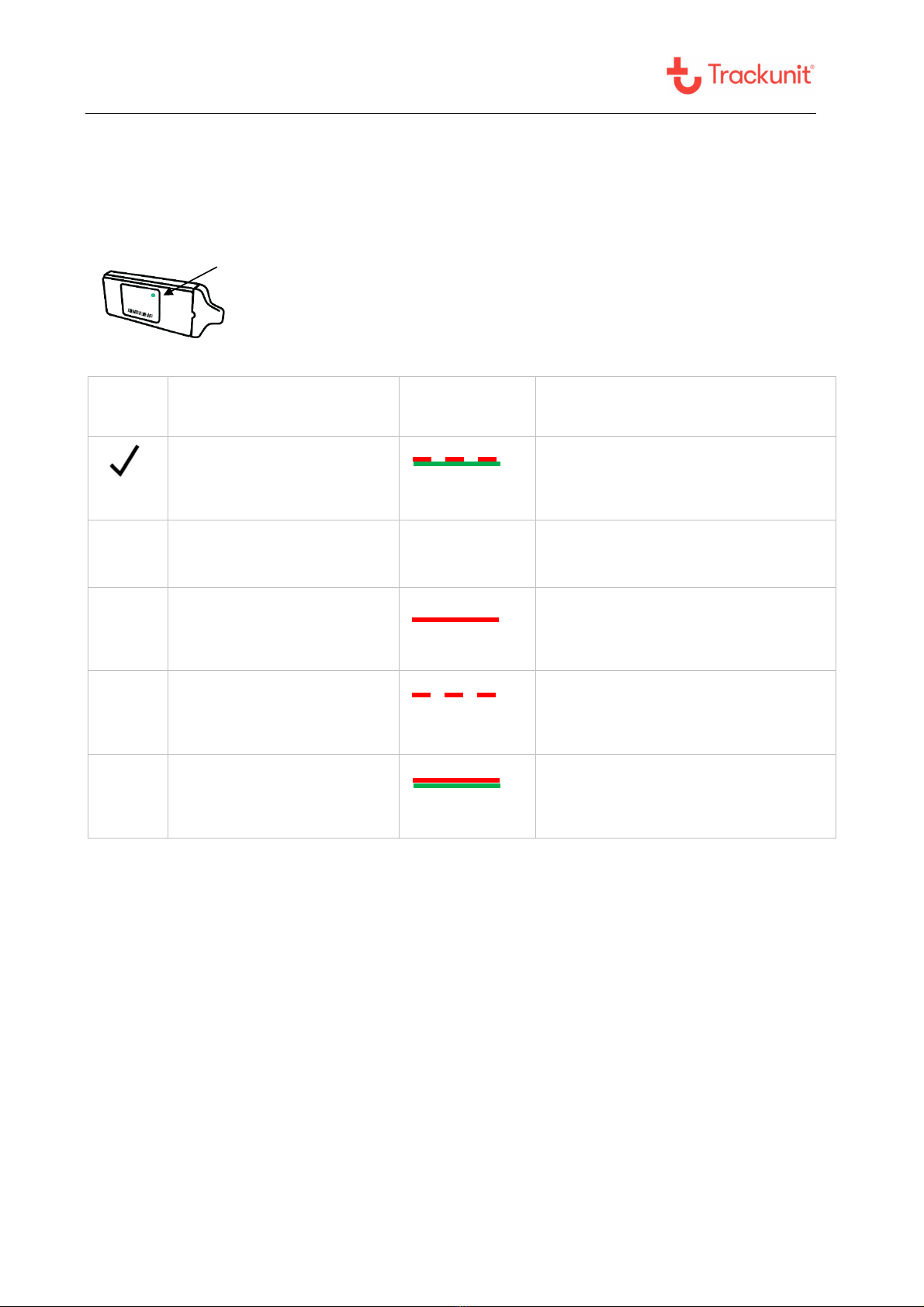
Check LED status – see page 6
No light in LED
Check if the red and blue wires are installed correctly or
if the fuse is blown
Constant red light
in LED
Verify location of the unit – see page 3
Move machine or vehicle for better SM signal
No green light in LED
Verify location of the unit – see page 3
Move machine or vehicle for better PS reception
Inputs counting operating
hours when machine is off
Possibly due to the main breaker being on the negative wire (ground
wire from the machine battery). When off, the inputs may register a
voltage level and start counting operating hours.
To avoid this situation, the digital input 4 (pink wire) should be
connected to the chassis/ground on the machine.
See Input filtering (INFILT) section, page 8.
Technical A i tance
If you experience an issue and cannot find the information you need in the product documentation, please
contact Trackunit.
Spare part lists:
Spare battery PN 4233.0002
HW shield for harsh environments PN. 7402.9551 and 7402.9552.
Fuse kits (30V/1A) for 12V-24V operations or (80V/3A) for 12V-48V operation.
Trackunit support: +45 96 73 74 00
Email: support@trackunit.com
The guides can also be downloaded online: www.trackunit.com/downloads
NB! When contacting technical support, please have the unit serial number ready.

TU600-x
Short uide TU600-x v0.2, January 2020, ©Trackunit 2020 11
Product pecification
Product
TU600
2 SM
Yes
LTE M1 / NB1 IOT
Yes
Operational voltage
(supply voltage)
12-48 V DC
Absolute maximum voltage
range
8-58 V DC continuous
Standby consumption
( SM-receiver active)
10 mA / 7 mA (avg. at 12V/24V)
Consumption during
charging an empty battery
225 mA / 115 mA (max at 12V/24V)
Charging time for an empty
backup-battery
4 hours at 25ºC / 77ºF)
Digital inputs
4
Digital outputs
1
CAN inputs (High / Low)
2
Access control input
M8 connector
1

TU600-x
Short uide TU600-x v0.2, January 2020, ©Trackunit 2020 12
Temperature range
In active running mode
-
20ºC to +55ºC/60ºC
Limited by the Li-Ion backup battery when the unit is either machinery or
battery powered.
Storage
-40ºC to +70ºC
Shorter battery lifetime must be expected when storage and operation
occur at extreme temperatures.
Mechanical pecification
Length 122,3 mm (4.8 in.)
Width 45.5 mm (1.8 in.) (50,1 mm incl. cradle) (1.9 in.)
Height 17.9 mm (0.7 in.) (22,7 mm incl. cradle) (0.9 in.)
Cable length 170 cm (5.6 ft.)
Environmental class IP67 (With HW Shield IP66k & IP69k – PN. 7402.9551 and 7402.9552)
Weight 66 g (excluding cable) (2.3 oz.)

TU600-x
Short uide TU600-x v0.2, January 2020, ©Trackunit 2020 13
Regulatory information and precaution
Use location
This equipment design applies to commercial or industrial equipment
expected to be installed in locations where only adults are normally present
Terms of use
Use only Trackunit approved accessories and/or batteries. Do not connect
incompatible products
New battery
In case of battery malfunction, expiration or any other situation where a new
battery might be needed, replacement batteries can be ordered through
support@trackunit.com
CE mark
The TU600 products complies with the essential requirements
of the RED Directive 2014/53/EU directive with respect to the EMC
requirements, safety and radio spectrum matters
FCC mark
The TU600 products contains radio transmitters and complies with the
essential requirements of Part 2.1091, 15.247, 22, 24, 27 and 90 of the FCC
rules, and with RSS- EN, RSS- 102, RSS-130, RSS-132, RSS-133, RSS-
139, and RSS247 of the Industry Canada requirements
Environmental
The TU600 products complies with the SAE J1455 environmental conditions
for heavy trucks when mounted in the vehicles. Additionally, compliance to
shock and acceleration by IEC 61373. The product protection covers IP67
(standalone) and IP66k &IP69k (With HW shield).
Charging
The battery will recharge as long as its temperature range is within 0ºC to
+45ºC and the vehicle to which the unit is mounted is running. In case of
temperatures outside this range the internal battery will not recharge.
Operating
conditions
The internal battery will operate in temperature ranges from -20ºC to +60ºC.
In case of temperatures outside of this range the internal battery will be
disabled by the device. Battery lifetime is expected to be 3 years under
normal operating conditions.

TU600-x
Short uide TU600-x v0.2, January 2020, ©Trackunit 2020 14
Fuse
Recommended fuse holders and fuses for installation up to 48V supply
voltages (can be ordered at Trackunit A/S):
a. Supply voltage 12V/24V (Max 30A)
i. ATO blade fuses (Max 32V/1A) used with Littelfuse FHAC0002SXJ fuse
holder (standard).
ii. ATP blade fuse (Max 32V/1A - ATO style) used with TaiTek FH-
006WR-12R-12-U fuse holder (standard).
b. Supply voltage 12V - 48V (Max 30A)
i. FKS blade fuse (Max 80V/3A - ATO style) used with Littelfuse FH2 fuse
holder (recommended).
Machinery
The TU600 product complies with the essential requirements of the Directive
2006/42/EC and EU regulation 167/2013 when integrated as intended:
I) ISO 13766-1 Earth-moving machinery and construction machinery
II) EN/ISO 14982 Agricultural and forestry machines.
III) EN 12895 Industrial trucks – Electromagnetic compatibility.
IV) UN regulative ECE R10 EMC rev. 5 in accordance with EU regulation
661/2009 for Electronic Sub-Assembly (ESA).
NOTE: Harmonized standards under the directive 2014/30/EU have been
applied.
Statement for ISO 13849-1:
The TU600-x are when installed not a vital part in the machine safety system,
but it can be used as access control/immobilizer if paired with a keypad (e.g.
DualID II) or Ibutton or by Bluetooth LE. This function depends on correct
installation (see installation guide) and requires that the output wire is
connected to a relay to control the starter motor, see installation diagram.
When the emergency stop on the machine is activated, the unit and keypad
functions will be disabled. The internal battery ensures that a PS position
still can be acquired on an hourly basis.
PRECAUTION: Trackunit recommend only mounting Output1 to tarter
motor through a relay and under no circum tance hould Output1 be
u ed to control the engine hutdown during operation or any moving
part on the machinery.

TU600-x
Short uide TU600-x v0.2, January 2020, ©Trackunit 2020 15
Approval and Certification
FCC/IC part 15.19
Notice
This device complies with Part 15 of the FCC Rules and with Industry
Canada license-exempt RSS standard(s). Operation is subject to the
following two conditions: (1) this device may not cause harmful
interference, and (2) this device must accept any interference received,
including interference that may cause undesired operation.
IC RSS- EN
Notice
Le présent appareil est conforme aux CNR d'Industrie Canada applicables
aux appareils radio exempts de licence. L'exploitation est autorisée aux
deux conditions suivantes: (1) l'appareil ne doit pas produire de brouillage,
et (2) l'utilisateur de l'appareil doit accepter tout brouillage radioélectrique
subi, même si le brouillage est susceptible d'en compromettre le
fonctionnement.
FCC part 15.21
Notice
Changes or modifications made to this equipment not expressly approved
by Trackunit may void the FCC authorization to operate this equipment.
FCC/IC
Radiofrequency
radiation exposure
Information
This equipment complies with FCC/IC radiation exposure limits set forth for
an uncontrolled environment. This equipment may be installed and
operated with minimum distance of 20 cm between the radiator and your
body.
This transmitter must not be co-located or operating in conjunction with any
other antenna or transmitter.
Environmental
compliance
SAE J1455 EN/IEC 60068-2-1:2007 Cold
SAE J1455 EN/IEC 60068-2-2:2006 Dry Heat
SAE J1455, IEC 61373 EN/IEC 60068-2-27:2010 Shock
SAE J1455 EN/IEC 60068-2-31:2008 Drop
SAE J1455, IEC 61373 EN/IEC 60068-2-64:2008 Random vibration
and acceleration
SAE J1455 EN/IEC 60068-2-78:2001 Damp heat steady state
SAE J1455 (IEC 60529+A1+A2)CSV:2013 Degrees of protection
(IPcode): IP67 and With HW hield: IP66k & IP69k
NOTE A:
The TU600 is not to be mounted in areas with presence of Motor oil,
asoline, Diesel fuel, Hydraulic fluid, Brake fluid, Transmission fluid,
lycol and water mixture etc.

TU600-x
Short uide TU600-x v0.2, January 2020, ©Trackunit 2020
16
NOTE B:
The housing not designed to withstand high pressure cleaning. Only use
the TU600 when mounted inside the designated Trackunit protection cap
(7402.9551 and 7402.9552 Trackunit Raw – Hardware Shield, can be
ordered at Trackunit A/S) in mounting areas where high pressure cleaning
is common procedure.
Regulatory
labeling
The TU600-x product family are regulatory compliant to the following
regulation:
PTCRB
certification for
interoperability
with mobile
networks
Selected variants of the TU600 products series under FCC ID: ZMF-TU600
and IC: 9746A-TU600 are certified for PTCRB interoperability with mobile
networks:
#77390: Trackunit TU600-5, HW 1.000, SW 60.012, SVN 7
Japan
The TU600-x model is certified for Japan under ID n°: [R] 003-180062, [R]
209-J00306, [T] D180034003
This device is granted pursuant to the Japanese Radio Law (電波法)
=
当該機器には電波法に基づく、技術基準適合証明等を受けた特定無線設備を装着して
いる
This device should not be modified (otherwise the granted designation
number will become invalid)
本製品の改造は禁止されています。(適合証明番号などが無効となります。)
Chile
Este equipo cumple con la Resolución No 403 de 2008, de la
Subsecretaria de telecomunicaciones, relativa a radiaciones
electromagnéticas.
Regulatory
accessed
countries
The regulatory accessed countries are countries without local registrations
or approvals. A manufacturer declaration of conformity assessment to the
national rules are applied for:
10R - 05 8766
FCC ID: ZMF-TU600
IC: 9746A-TU600

TU600-x
Short uide TU600-x v0.2, January 2020, ©Trackunit 2020 17
Americas: Chile (Regulatory label)
Asia: Myanmar
Certified countries
The TU600-5 model is additionally certified for countries that has no
regulatory label requirements:
India, Kuwait, Qatar, Saudi Arabia.
The certificates can be requested at Trackunit A/S for use for import
declarations.
Table of contents
Other Trackunit GPS manuals