Trackunit TU501 Series Supplement

NOTE: Former model ID was ME501-x (2G/3G). Model ID changed in 2017 to TU501-x (2G/3G)
Short guide : TU501-x
Version 4.2, May 2019

TU501-x
Short Guide TU501-x v4.2, May 2019, ©Trackunit 20192
Index
Practical Advice .......................................................................................... 3
Machine and vehicle guidelines for correct wiring....................................... 4
Installation example .................................................................................... 5
Functionality check: LED on the unit........................................................... 6
Installation check and update using “Verify my Trackunit” .......................... 7
Input filtering (INFILT)................................................................................. 8
CAN bus termination resistor ...................................................................... 9
Troubleshooting........................................................................................ 10
Product specifications............................................................................... 11
Temperature range ................................................................................... 12
Mechanical specifications ......................................................................... 12
Regulatory information and precautions.................................................... 13
Approvals and Certifications ..................................................................... 15

TU501-x
Short Guide TU501-x v4.2, May 2019, ©Trackunit 20193
Practical Advice
1. Save important numbers
2. Installation is best done outside
3. Correct positioning of the unit
The serial number is
located on the unit.
The mobile number
and unit serial number
are located on the box
label. It can be peeled
off and saved for later
use.
Do not perform
installation inside a
building.
Install the unit outside
for better GPS and
GSM/UMTS signal.
Position the unit as
shown for optimal
signal conditions.
Avoid installing the unit
directly under a layer of
metal or next to wires.
S/N xxxxxx
TU501-x
Short Guide TU501-x v4.2, May 2019, ©Trackunit 20194
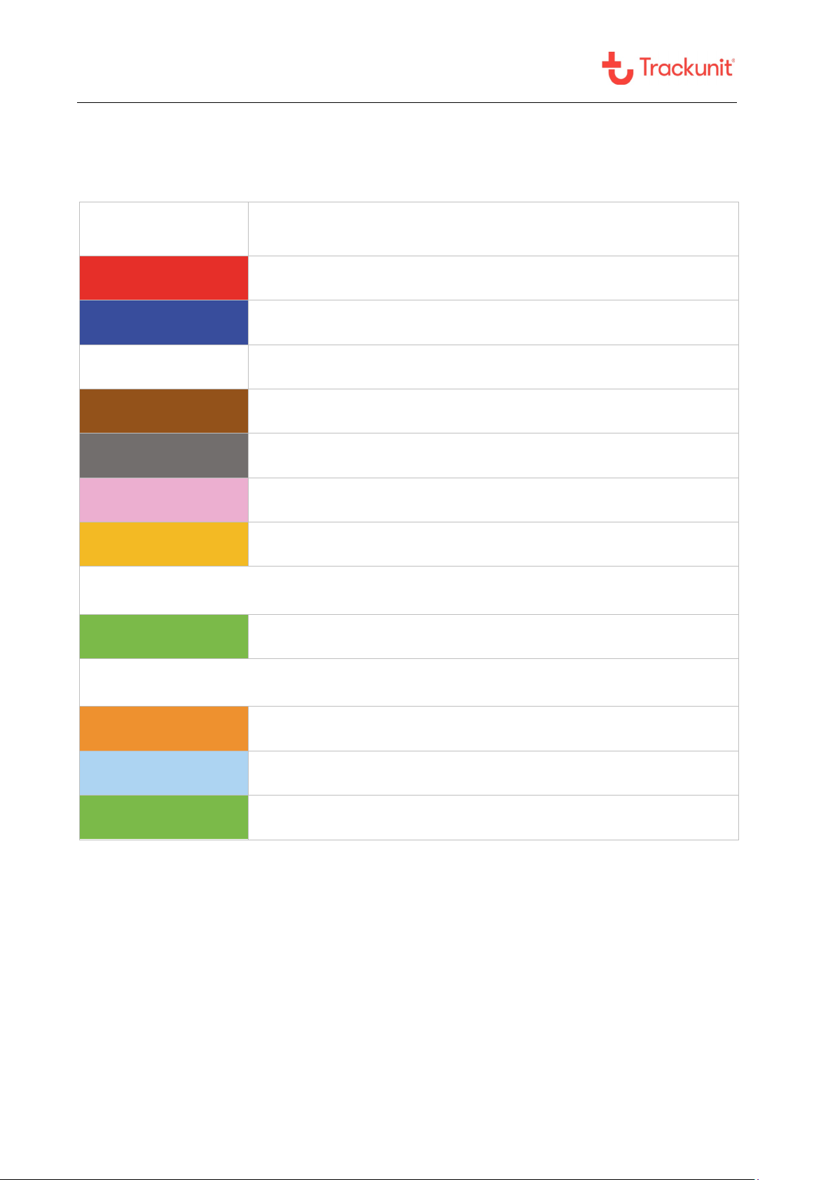
Machine and vehicle guidelines for correct wiring
Wire color
Description
Power Connect to machine battery through a fuse (mandatory)1
Ground Connect to ground (mandatory)
Digital input 1 Can be connected to hour counter. Optional input2
Digital input 2 Connect to the ignition signal (mandatory for vehicles and machines)1
Digital input 3 Optional input1
Digital input 4 Can be used for INFILT function. Optional input2
Digital output 1 Can be used to control a relay3/4
Additional input for TU501-2
1 – Wire input M8 connector for access control and temperature sensor
Additional input for TU501-4
CAN High Connect to CAN High
CAN Low Connect to CAN Low
1 – Wire input M8 connector for access control and temperature sensor
1: Supply voltage range 12–48V
2: Active/high when min. 9,5V DC at input
3: Max. load 200 mA
4: Do NOT use this output to switch off vehicles and machines during operation or driving

TU501-x
Short Guide TU501-x v4.2, May 2019, ©Trackunit 20195
Installation example

TU501-x
Short Guide TU501-x v4.2, May 2019, ©Trackunit 20196
Functionality check: LED on the unit
Status
LED mode
LED color
Status indication
Red flashing light and constant
green light in LED
- Mobile network is OK and GPS
has valid satellite position
!
No light in LED
- No power supply
!
Constant red light and no green
light in LED
- Power supply is OK, but NO mobile network
- GPS has NO satellite position
!
Red flashing light and no green
light in LED
- Mobile network is OK
- GPS has NO satellite position
!
Constant red and green light in
LED
- Power supply is OK, but NO mobile network
- GPS has valid satellite position
LED
LE

TU501-x
Short Guide TU501-x v4.2, May 2019, ©Trackunit 20197
Installation check and update using
“Verify my Trackunit”
Step 1: Login
- Go to
http://verify.trackunit.com
- Enter user name and
password
Step 2: Find unit
- Enter serial number and
then click “Find”
Step 3: Review
status
- Time of last received data
- GPS and mobile signal
- Mobile number
- Power supply voltage
- Internal battery voltage
- Status of inputs 1-4
(on/off)
- Click “Find” again to
refresh status
Step 4: Basic
configuration
options
- Enter a device name
- Enter engine hours
- Enter start distance
- Select category
- Connect up to multiple
groups
- Add a note (visible in
Trackunit Manager)
Step 5: Logout
- Click “Update” to save
- Click “Logout”
Note
- Prior to verification, make
sure the unit is installed
and active in an area with
sufficient GPS and mobile
coverage.
TU501-x
Short Guide TU501-x v4.2, May 2019, ©Trackunit 20198
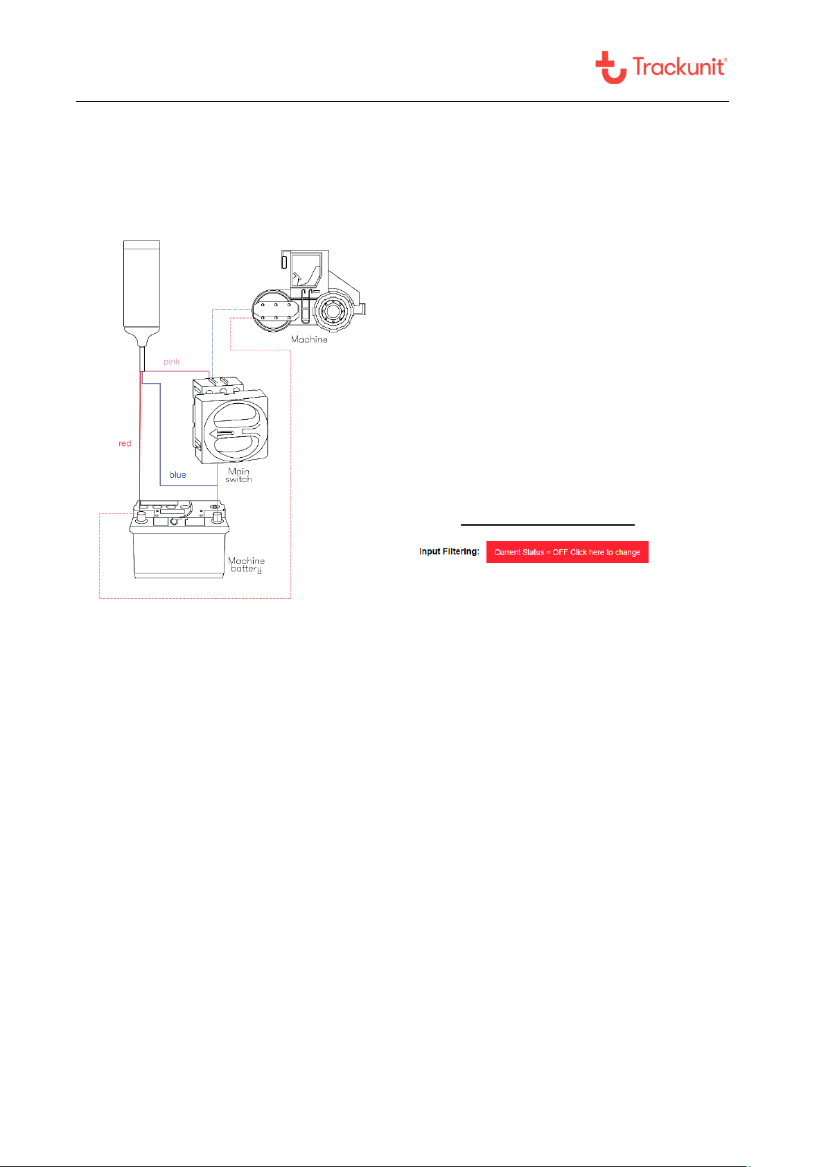
Input filtering (INFILT)
In case the main breaker is on the negative
wire (ground wire from the machine battery),
the inputs may register a voltage level and
start counting operating hours.
To avoid this situation, the digital input 4
(pink wire) should be connected to the
chassis/ground on the machine.
The infilt function should be activated via
“Verify my Trackunit”
Activation of input filtering
Go to: http://verify.trackunit.com/
NB! Enabling the filtering function will
disable inputs 1 to 3 when input 4 is
on/active. This can prevent all digital input
alarms. It will also disable the use of any
alarm function on digital input 4.

TU501-x
Short Guide TU501-x v4.2, May 2019, ©Trackunit 20199
CAN bus termination resistor
When installing the TU501-4 on a J1939 CAN-bus, it is very important to determine if the
installation is on a “private” CAN-bus directly to the CAN controller, or if the TU501-4 is to be
installed as a stub on a CAN-bus with multiple CAN devices already attached.
The 120-ohm termination resister is a permanently installed resistor, so make sure to use and
select the correct TU501-4 CAN-bus version.
With 120-ohm bus termination (directly connected)
Without bus termination (stub connected)
NB! When the unit is stub connected, the wire length must be minimized to avoid CAN-bus noise and
error ratio.

TU501-x
Short Guide TU501-x v4.2, May 2019, ©Trackunit 201910
Troubleshooting
Error description
Possible solutions
No reply on SMS command
•Verify correct GSM number
•Check LED status – see page 6
No light in LED
•Check if the red and blue wires are installed correctly or
if the fuse is blown
Constant red light
in LED
•Verify location of the unit – see page 3
•Move machine or vehicle for better GSM signal
No green light in LED
•Verify location of the unit – see page 3
•Move machine or vehicle for better GPS reception
Inputs counting operating
hours when machine is off
•Possibly due to the main breaker being on the negative wire (ground
wire from the machine battery). When off, the inputs may register a
voltage level and start counting operating hours.
•To avoid this situation, the digital input 4 (pink wire) should be
connected to the chassis/ground on the machine.
•See Input filtering (INFILT) section, page 8.
Technical Assistance
If you experience an issue and cannot find the information you need in the product documentation, please
contact Trackunit.
Trackunit support: +45 96 73 74 00
Email: support@trackunit.com
The guides can also be downloaded online: www.trackunit.com/downloads
NB! When contacting technical support, please have the unit serial number ready.

TU501-x
Short Guide TU501-x v4.2, May 2019, ©Trackunit 201911
Product specifications
TU501-9
Standard
TU501-2
Access
TU501-4
Access/CAN
2G GSM
Yes
3G UMTS
Yes
Operational voltage
(supply voltage)
12-48 V DC
Absolute maximum voltage
range
8-58 V DC continuous
Standby consumption
(GSM-receiver active)
10 mA / 7 mA (avg. at 12V/24V)
Consumption during charging
an empty battery
225 mA / 115 mA (max at 12V/24V)
Charging time for an empty
backup-battery
4 hours at 25ºC / 77ºF)
Digital inputs
4
Digital outputs
1
CAN inputs (High / Low)
0 0 2
Access control input
M8 connector
0 1 1

TU501-x
Short Guide TU501-x v4.2, May 2019, ©Trackunit 201912
Temperature range
In active running mode*
-
20ºC to +55ºC/60ºC
Limited by the Li-Ion backup battery when the unit is either machinery or
battery powered.
Storage**
-40ºC to +70ºC
Shorter battery lifetime must be expected when storage and operation
occur at extreme temperatures.
Mechanical specifications
Length 106 mm (4.17 in.)
Width 45 mm (49 mm incl. cradle) (1.9 in.)
Height 18 mm (23 mm incl. cradle) (0.9 in.)
Cable length 170 cm (5.6 ft.)
Environmental class IP67
Weight 65 g (excluding cable) (2.3 oz.)

TU501-x
Short Guide TU501-x v4.2, May 2019, ©Trackunit 201913
Regulatory information and precautions
Use location
This equipment design applies to commercial or industrial equipment
expected to be installed in locations where only adults are normally present
Terms of use
Use only Trackunit approved accessories and/or batteries. Do not connect
incompatible products
New battery
In case of battery malfunction, expiration or any other situation where a new
battery might be needed, replacement batteries can be ordered through
CE mark
The TU501 products comply with the essential requirements of the RED
2014/53/EU directive with respect to the EMC requirements, safety and radio
spectrum matters.
FCC mark
The TU501 products contain radio transmitters and comply with the essential
requirements of Part 15, 22 and 24 of the FCC rules, and with RSS-GEN,
RSS-132, RSS-133, RSS-210 and ICES-003 of the Industry Canada
requirements.
Environmental
The TU501 products comply with the environmental conditions for rolling
stock and transportation according to DIN EN 50125-1 and
IEC 61373 / DIN EN 61373 with the IP67 classification including
vibrations/drop according to SAE J1455 (heavy trucks).
Charging
The battery will recharge as long as its temperature range is within 0ºC to
+45ºC and the vehicle to which the unit is mounted is running. In case of
temperatures outside this range the internal battery will not recharge.
Operating
conditions
The internal battery will operate in temperature ranges from -20ºC to +60ºC.
In case of temperatures outside of this range the internal battery will be
disabled by the device. Battery lifetime is expected to be 3 years under
normal operating conditions.
Long term
storage
/operating
conditions
It is recommended to remove the battery during long term storage/continuous
operation outside the temperatures specified in the operating conditions.

TU501-x
Short Guide TU501-x v4.2, May 2019, ©Trackunit 201914
Fuse
Recommended fuse holders and fuses for installation up to 48V supply
voltages (can be ordered at Trackunit A/S):
a. Supply voltage 12V/24V (Max 30A)
i. ATO blade fuses (Max 32V/1A) used with Littelfuse FHAC0002SXJ fuse
holder (standard).
ii. ATP blade fuse (Max 32V/1A - ATO style) used with TaiTek FH-
006WR-12R-12-U fuse holder (standard).
b. Supply voltage 12V - 48V (Max 30A)
i. FKS blade fuse (Max 80V/3A - ATO style) used with Littelfuse FH2 fuse
holder (recommended).
Machinery
The TU501 products comply with the essential requirements of the Directive
2006/42/EC and EU regulation 167/2013 when integrated as intended:
I. EN 13309 Construction machinery
II. ISO 13766 Earth-moving machinery
III. EN/ISO 14982 Agricultural and forestry machines.
IV. UN regulative ECE R10 EMC rev. 4 in accordance with EU regulation
661/2009 for Electronic Sub-Assembly (ESA).
NOTE: Harmonized standards under the directive 2014/30/EU have been
applied.

TU501-x
Short Guide TU501-x v4.2, May 2019, ©Trackunit 201915
Approvals and Certifications
FCC/IC part 15.19
Notice
This device complies with Part 15 of the FCC Rules and with Industry
Canada license-exempt RSS standard(s). Operation is subject to the
following two conditions: (1) this device may not cause harmful
interference, and (2) this device must accept any interference received,
including interference that may cause undesired operation.
IC RSS-GEN
Notice
Le présent appareil est conforme aux CNR d'Industrie Canada applicables
aux appareils radio exempts de licence. L'exploitation est autorisée aux
deux conditions suivantes: (1) l'appareil ne doit pas produire de brouillage,
et (2) l'utilisateur de l'appareil doit accepter tout brouillage radioélectrique
subi, même si le brouillage est susceptible d'en compromettre le
fonctionnement.
FCC part 15.21
Notice
Changes or modifications made to this equipment not expressly approved
by Trackunit may void the FCC authorization to operate this equipment.
FCC/IC
Radiofrequency
radiation exposure
Information
This equipment complies with FCC/IC radiation exposure limits set forth for
an uncontrolled environment. This equipment may be installed and
operated with minimum distance of 5 cm between the radiator and your
body.
This transmitter must not be co-located or operating in conjunction with any
other antenna or transmitter.
Environmental
compliance
IEC 61373 - EN/IEC 60068-2-1:2007 - Cold
IEC 61373 - EN/IEC 60068-2-2:2006 - Dry Heat
EN 50125-1 - EN/IEC 60068-2-27:2010 - Shock
SAE J1455 - EN/IEC 60068-2-31:2008 - Drop
EN 50125-1, SAE J1455 - EN/IEC 60068-2-64:2008 - Random vibration
IEC 61373 - EN/IEC 60068-2-78:2001 - Damp heat steady state
IEC 61373 - (IEC 60529+A1+A2) CSV:2013 - Degrees of protection (IP
code): IP67
NOTE A: The TU501 is not to be mounted in areas with presence of motor
oil, gasoline, diesel fuel, hydraulic fluid, brake fluid, transmission fluid,
glycol and water mixture, etc.
NOTE B: The housing is not designed to withstand high pressure cleaning.
Only use the TU501 when mounted inside the designated Trackunit
protection cap (7402.9551 Trackunit Raw hardware shield can be ordered
at Trackunit) in mounting areas where high pressure cleaning is common
procedure.

TU501-x
Short Guide TU501-x v4.2, May 2019, ©Trackunit 201916
Regulatory
labeling
E4857
ЕАЭС N RU Д-DK.ЭМ03.В.00175
PTCRB
certification for
interoperability
with mobile
networks
Selected variants of the TU501 products series under FCC ID: ZMF-ME501
and IC: 9746A-ME501 are certified for PTCRB interoperability with mobile
networks:
#47125: Trackunit ME501-5 (New model ID: TU501-5)
#54393: Trackunit ME501-4 (New model ID: TU501-4)
#54394: Trackunit ME501-9 (New model ID: TU501-9)
Japan
ID n°: [R] 003-150064, [T] D150059003
This device is granted pursuant to the Japanese Radio Law (電波法)
=当該機器には電波法に基づく、技術基準適合証明等を受けた特定無線設
備を装着している
This device should not be modified (otherwise the granted designation
number will become invalid)
本製品の改造は禁止されています。(適合証明番号などが無効となります
。)
Chile
Este equipo cumple con la Resolución No 403 de 2008, de la
Subsecretaria de telecomunicaciones, relativa a radiaciones
electromagnéticas.
Regulatory
accessed
countries
The regulatory accessed countries are countries without local registrations
or approvals. The following countries are accessed:
Americas: Chile
Middle East: Israel
Asia: Myanmar, India
10R - 04 7440
FCC ID: ZMF-E501
IC: 9746A-ME501
This manual suits for next models
3
Table of contents
Other Trackunit GPS manuals


