Topnics TP-GPS600 User manual

4G Car GPS Tracker
TP-GPS600
User Manual
Preface
Thank you for choosing the 4G Vehicle GPS tracker.This manual shows how to
operate the device smoothly and correctly.Make sure to read this manual carefully before
using this product. Please note that specification and information are subject to changes
without prior notice in this manual. Any change will be integrated in the latest release.The
manufacturer assumes no responsibility for any errors or omissions in this document.

Contents
1. Overview .........................................................................................................................1
2. Application.......................................................................................................................1
3. Specifications..................................................................................................................1
4. MT600 and Accessories................................................................................................3
5. Appearance.....................................................................................................................3
6. First use..........................................................................................................................4
6.1 SIM Card installation............................................................................................4
6.2 Indications..............................................................................................................5
6.2.1 CHG-Charge indicator(RED)......................................................................5
6.2.2 SYS-System indicator(BLUE).....................................................................5
6.2.3 GPS-GPS indicator(GREEN).....................................................................5
6.3 Device Button Instruction............................................................................................5
6.4 Install 4G/GPS Antenna..............................................................................................6
6.5 Install the Power Wire & Relay.................................................................................6
6.6 Install the SOS ............................................................................................................7
6.7 Areas for Installation....................................................................................................7
6.7.1 Caution ...............................................................................................................7
6.7.2 For added protection.........................................................................................7
7. Main Operation and Application...................................................................................8
7.1 Set Authorization Phone Number .......................................................................8
7.2 Delete authorization number................................................................................8
7.3 Change the password..........................................................................................8
7.4 Single Locating .....................................................................................................8
7.5 SOS Alarm............................................................................................................8
7.6 Geo-fence..............................................................................................................8
7.6.1 Enable the Geo-fence................................................................................8
7.6.2 Disable the Geo-fence...............................................................................8
7.7 Remote cut off fuel and power ..........................................................................9
7.8 External power cut off alarm ..............................................................................9
7.9 Towing alarm ........................................................................................................9
7.10 Low battery Alarm(backup battery)...................................................................9
7.11 Low battery Alarm(car battery)..........................................................................9
7.12 High Temperature Alarm....................................................................................9
7.13 Over-speed alarm...............................................................................................9
7.14 Set time zone.....................................................................................................9
7.15 Set GPRS user name........................................................................................9
7.16 Set APN(Access Point Name) ........................................................................10
7.17 Set Server IP and PORT................................................................................10
7.18 Set GPRS Upload Interval Time ....................................................................10
7.18.1 ACC ON(Upload status is AUTO)........................................................10

7.18.2 ACC OFF&Vehicle Move(Upload status is TOWED) .........................10
7.18.3 ACC OFF&Vehicle Still(Upload status is AUTOLOW)........................10
7.19 Invalid GPS Data Upload................................................................................10
7.20 SMS Response ON/OFF .................................................................................10

1
1. Overview
MT600 is the latest 4G GPS Tracker support LTE/UMTS/GSM.This device can locate
and monitor any remote targets by SMS or server. The user also can remote cut off
oil/power and check the historical record.
The unit features excellent and stable work performance.It used for vehicle tracking
and fleet management.
2. Application
4GLTE network support
Real-time position inquire
Vehicle trip history on web
SOS alarm
ACC switch alarm
Geo-fence alarm
External power cut off alarm
Remote cut off fuel/power
Vehicle towing alarm
Overspeed alarm
Backup battery low power alarm
Car battery low power alarm
High temperature alarm
Power saving mode
Camera(optional)
Door sensor(optional)
Fuel sensor(optional)
3. Specifications
Item
Specifications
Dimension
90(L)*70(W)*24(H)mm
Weight
140g
Input Voltage
12V-36V
Backup battery
700mAh/3.7v
GPS Chip
U-BLOX7
GPS Sensitivity
-162dBm
Channel
56 Channel
Item
Specifications

2
4G Frequency bands
TP-GPS600
FDD LTE: 800/850/900/1800/2100/2600MHz
UMTS: 850/900/2100MHz
GSM: 850/900/1800/1900MHz
600-A
FDD LTE: 700/850/1700/1900MHz
UMTS: 850/1700/1900MHz
GSM: 850/1900MHz
600-C (Standard Version)
FDD LTE: 900/1800/2100MHz
TDD LTE: 1900/2300/2500/2600MHz
TDSCDMA: B34/B39
UMTS: 900/2100MHz
GSM: 900/1800MHz
Positioning Accuracy
10m
Hot start
1s on average
Warm start
15s on average
Cold start
30s on average
Humidity
5%~95% non-concretion
Working temperature
-20°C to 70°C
Power consumption
70mA standby current
Antenna
external 4G/GPS antenna
Sensor
3D acceleration sensor, temperature sensor
3
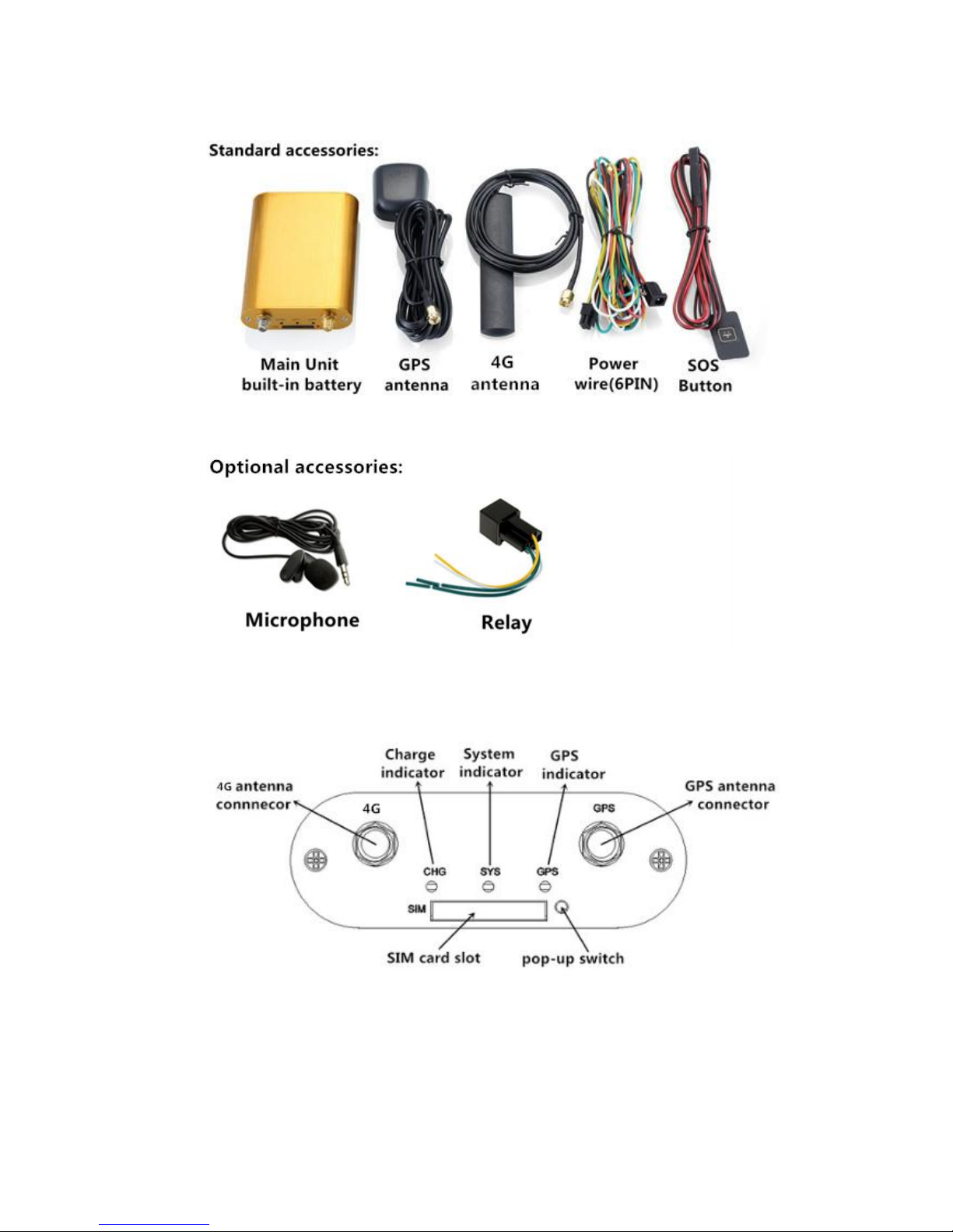
4. TP-GPS600 and Accessories
5. Appearance
4
6. First use
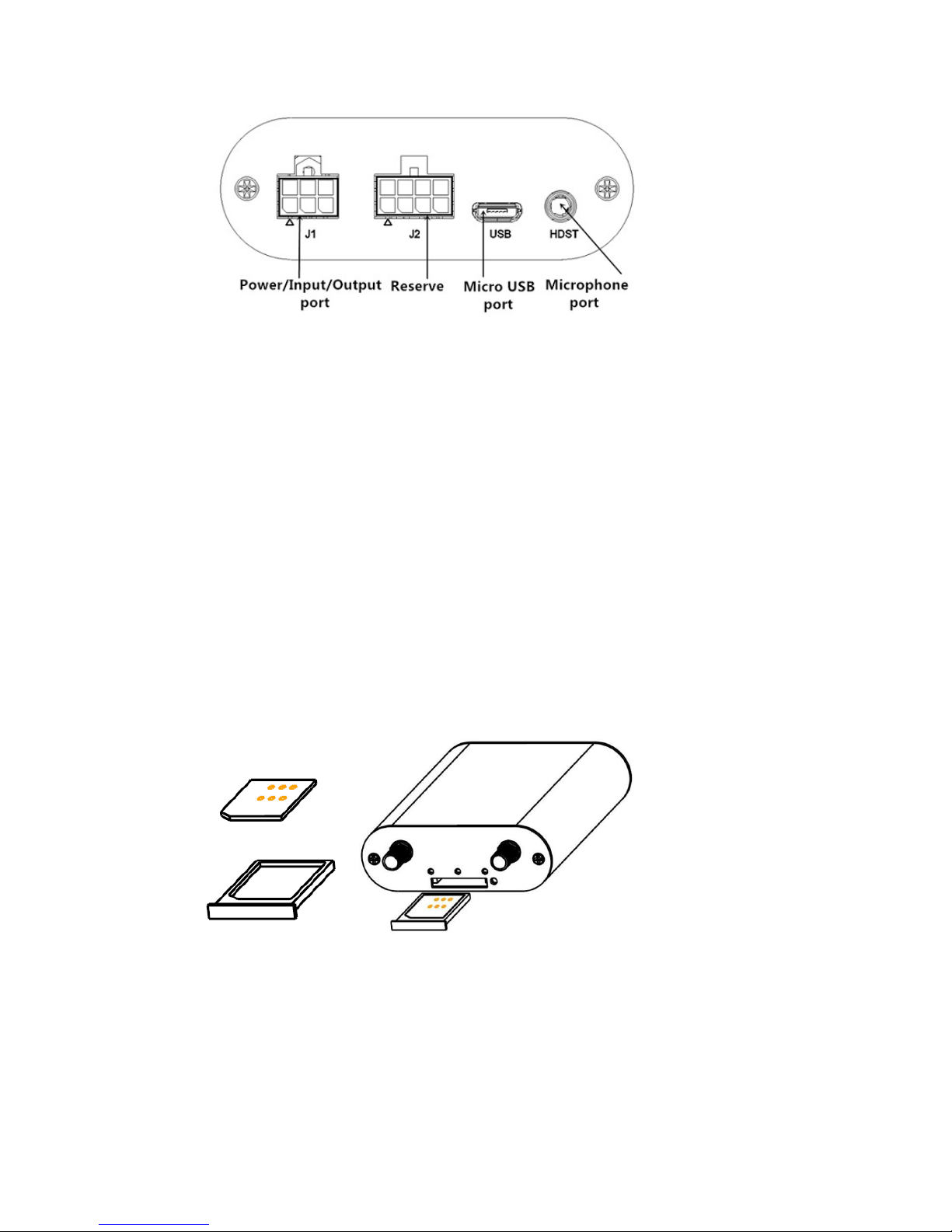
6.1 SIM Card installation
Pay attention to the following items before installing the SIM card:
Ensure the SIM card have enough balance
Ensure the SIM card enable caller ID and GPRS function
Ensure the SIM card disable PIN password and call forwarding function.
Power off the device before installing the SIM card
To install the SIM card, perform the following operations:
1. Insert the SIM card to the SIM card slot. Ensure the card chip facing up(see
PIC1).
2. Put the SIM card slot back(see PIC2).
Note: If you want to take out the SIM card, use the tweezers to press the SIM card pop-up
switch, the SIM card slot will pop up.
PIC1 PIC2
5
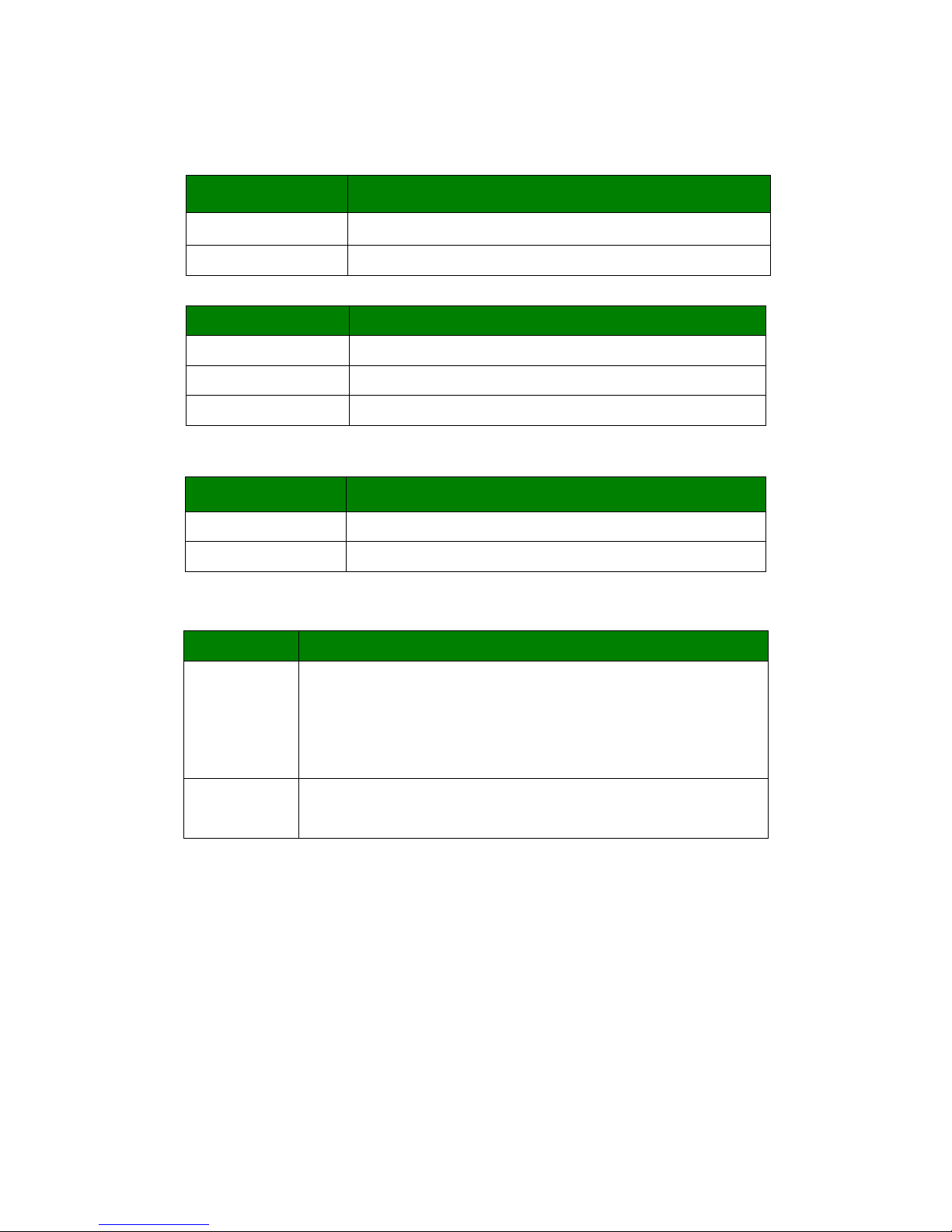
6.2 Indications
6.2.1 CHG-Charge indicator(RED)
6.2.2 SYS-System indicator(BLUE)
Status
Description
Always ON
No SIM Card or no 3G network
OFF
Parked
Quick flash (8s/time)
Work mode
6.2.3 GPS-GPS indicator(GREEN)
6.3 Device Button Instruction
Button
Description
Power Button
Insert the SIM card slot toPOWER ON, take out SIM card slot
to POWER OFF.
Connect the external power to POWER ON, disconnect the
power to POWER OFF
SOS Button
(optional)
Press and hold the button for 3 seconds,the unit will upload
data to server
Status
Description
Always ON
Under charging
OFF
not charging
Status
Description
OFF
GPS unavailable
Quick flash(1s/time)
GPS available
6
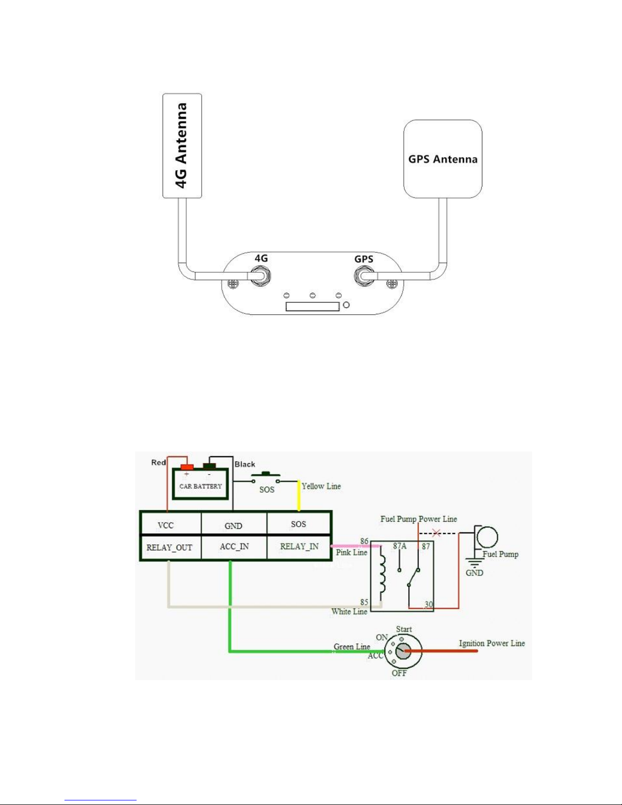
6.4 Install 4G/GPS Antenna
Connect the 4G antenna to the connector which is labeled "4G". The
4G antenna is non-directional, so you can hide it inany place of a vehicle.
Connect the GPS antenna to the connector which is labeled "GPS". It is
recommended that the antenna is facing up to the skyand the antenna side with
words is upwards. Secure the antenna by using double sided tapes
Note: Do not install the GPS antenna at a place with metal.
6.5 Install the Power Wire & Relay
When you get the device please connect the wire as follow:
Red: Connect to Car battery(+)
Black: Connect to Car battery(-)

7
Green: Connect to ACC
Yellow: Connect to SOS
White: Connect to Relay(85)
Pink: Connect to Relay(86)
Note: Relay is optional.
6.6 Install the SOS
Red: connect to Yellow of Power wire
Black: connect to Black of power wire
6.7 Areas for Installation
Displayed are our recommended areas available within a car that can be used to hide
the GPS Tracker. For additional security, you may install in other areas your desire.
6.7.1 Caution
Do not place the unit under metal surfaces.
Do not install next to radio, speakers or alarm systems.
It must be rigidly mounted on the surface.
Do not place the unit next to heat or moving parts.
It is recommended to place the unit near areas open to the sky
(dashboard, rear windscreen, C-Pillar areas, doors, etc)
Device can be placed in other areas of the vehicle (internally or
externally in car, truck, motorcycle) wherever there is visibility to the satellites.
6.7.2 For added protection
Thief would normally inspect the dashboard area for GPS tracking
system. Thus, install the unit in random areas to minimize the chances of the
tracker being discovered.
Do not let people know the existence and whereabout of your GPS
tracking unit.
Install connecting wires as discreetlyas possible,making it less obvious
and harder to notice.

8
7. Main Operation and Application
7.1 Set Authorization Phone Number
Instruction format: *cell phone number *password*serial number(1-3)**
For example:*13424392330*0000*1**
Reply:SET USER NUMBER 1 OK.
Note:
The device defaulted password is 0000.
The device can only authorized 3 cell phone numbers
7.2 Delete authorization number
Instruction format:**password*number(1-3)**
For example:**0000*1**
Reply:DELETE USER NUMBER 1 OK.
7.3 Change the password
Instruction format:777+new password+old password
For example:77712340000
Reply:SET USER PASSWORD OK.
7.4 Single Locating
Instruction format:666+password
For example:6660000
Description:Send this SMS command to unit,it will reply SMS as follow:
ID:865662000409210
Date:05:36:59 15/08/2015
Fix:AState:SMS
http://maps.google.com/maps?q=+22.63146%2c1+14.03701
7.5 SOS Alarm
When press SOS button for 3 seconds,it will upload data to server, the state is “SOS”
7.6 Geo-fence
Instruction format:006+password+G1,IO/I/O,E/W longitude upper limit+N/S latitude
upper limit,E/W longitude lower limit+N/S latitude lower limit.
For example:0060000G1,IO,E114.04540N22.59034,E114.05978N22.59797
Reply:SET SQUARE GEO-FENCE1(IO)OK.
7.6.1 Enable the Geo-fence
Instruction format:311+password
For example:3110000
Reply:SET SQUARE GEO-FENCE: ON.
7.6.2 Disable the Geo-fence
Instruction format:310+password
For example:3100000
Reply:SET SQUARE GEO-FENCE: OFF.

9
7.7 Remote cut off fuel and power
Cut off fuel and power: 940+user password
For example: 9400000
Reply: SET OILWAY DISCONNECT
Resume fuel and power: 941+user password
For example: 9410000
Reply: SET OILWAY RECOVERY CONNECT.
Note:The default is OFF
7.8 External power cut off alarm
If the external power wire is disconnect, it will send SMS to authorization phone
number and upload data to server, the state is:DEF.
7.9 Towing alarm
If the vehiclewas be towed whenACC is OFF, it will send SMS to authorization phone
number and upload data to server, the state is:TOWED.
7.10 Low battery Alarm(backup battery)
When the devicebattery is low power,it will send SMS to authorization phone number
and upload data to server, the state is:BLP.
7.11 Low battery Alarm(car battery)
When the vehicle battery is low power,it will send SMS to authorization phone number
and upload data to server, the state is:CLP.
7.12 High Temperature Alarm
When the device temperature is higher,it will send SMS to authorization phone
number and upload data to server, the state is:HD.
7.13 Over-speed alarm
Command:#122#user password#X##
Example:#122#0000#120##
Reply:SET SPEED LIMIT:ON
Close command: #122#0000#0##
SET SPEED LIMIT:OFF.
Note:X is speed value, unit is KM/H definition is [0, 999].
7.14 Set time zone
Instruction format:896+password++/-HH:MM
For example:8960000+08:00
Reply: SET TIME ZONE:+08:00
The default is Greenwich time(UTC).
7.15 Set GPRS user name
Instruction format: #801#password#new user name##
For example: #801#0000#MT500##
Reply: SET SERVER USERNAME OK.

10
7.16 Set APN(Access Point Name)
Instruction format 1:#803#user password#APN##
For example: #803#0000#CMNET##
Instruction format 2:#803#password#APN#APN user name# APN password##
For example: #803#0000#CMNET#INTERNET#INTERNET##
Reply: SET GPRS APN OK.
7.17 Set Server IP and PORT
Instruction format:#804#password#IP address(or domain) #port##
Example: #804#0000#192.168.1.1#8080## or #804#0000#www.mictrack.com#80##
Reply:SET SERVER IPAND PORT OK.
7.18 Set GPRS Upload Interval Time
7.18.1 ACC ON(Upload status is AUTO)
Instruction format:#805#password#interval time##
For example:#805#0000#30#1##
Reply:SET GPS PERIODIC UPLOAD OK.
Note: interval time define is[10,65535] seconds,.If interval time is 0, it will stop upload
and reply: SET GPS PERIODIC UPLOAD OK
7.18.2 ACC OFF&Vehicle Move(Upload status is TOWED)
Instruction format:#809#password#interval time##
For example:#809#0000#60#1##
Reply:SET GPS TOWED UPLOAD OK.
Note: interval time define is[10,65535] seconds,.If interval time is 0, it will stop upload
and reply: SET GPS TOWED UPLOAD OK.
7.18.3 ACC OFF&Vehicle Still(Upload status is AUTOLOW)
Instruction format:#807#password#interval time##
For example:#807#0000#10#1##
Reply:SET GPS POWER SAVING UPLOAD ON.
Note: interval time define is[2,1440] minuets,. If interval time is 0, it will stop upload
and reply: SET GPS POWER SAVING UPLOAD OFF.
7.19 Invalid GPS Data Upload
Invalid data upload ON:081+users password
For example:0810000
Reply:INVALID DATA UPLOAD:ON
Invalid data upload OFF:080+user password
For example:0800000
Reply:INVALID DATA UPLOAD:OFF
7.20 SMS Response ON/OFF
SMS OFF:160+ user password
For example:1600000
Reply:SET SEND SMS:OFF.
SMS ON:161+ user password

11
For example:1610000
Reply:SET SEND SMS:ON.
Table of contents
Other Topnics GPS manuals


