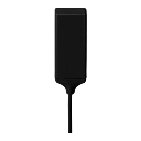
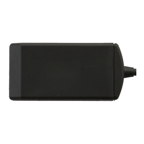
Trackunit TU600 Series User manual

TU600-X
TU600-X
Technical Manual
Version 1.0, December 2019

TU600-X
Trackunit TU600-X, Technical Manual v1.0, December 2019 Page 2
Content
Content .......................................................................................................... 2
Introduction .................................................................................................... 7
Related Information .......................................................................................................... 7
Safety first...................................................................................................... 7
Simple Guidelines ............................................................................................................ 7
Do Not Operate Where Prohibited ................................................................................... 7
Interference ...................................................................................................................... 8
Avoid Body Contact with Device during Operation ........................................................... 8
Qualified Service .............................................................................................................. 8
Accessories and Batteries ................................................................................................ 8
Water-Resistance ............................................................................................................. 8
Detailed Safety Information ............................................................................ 8
Exposure to Radio Frequency Signals ............................................................................. 8
Electronic Devices ............................................................................................................ 9
Pacemakers ..................................................................................................................... 9
Other Medical Devices ..................................................................................................... 9
Vehicles ............................................................................................................................ 9
Posted Facilities ............................................................................................................. 10
Aircrafts .......................................................................................................................... 10
Potentially Explosive Atmospheres ................................................................................ 10
For Vehicles Equipped with an Airbag............................................................................ 10
Specific Human Absorption Rates (SAR) ....................................................................... 10
Battery Safety Information .............................................................................................. 11
Automatic battery safety during operation .................................................................. 11
Delivered standard content .......................................................................... 12
Ready-to-Use, No Custom Programming Required ....................................................... 12
Cost-effective, Universally Available Communications ................................. 12
Use location - Children not likely to be present .............................................................. 13
Practical installation advice ............................................................................................ 13
Installation for insurance and anti-theft purpose ............................................................. 13
Connections ................................................................................................................... 14
Power supply .............................................................................................................. 14
Digital inputs ............................................................................................................... 14
Digital output ............................................................................................................... 14
Motion/acceleration sensor ......................................................................................... 14
Installing the TU600-X as to surpass the main switch on the machine. ...................... 15
Functionality check ...................................................................................... 16
“Verify my Trackunit” ...................................................................................................... 17
Troubleshooting ........................................................................................... 18
Installation of the digital output .................................................................... 19
SMS commands for output control ................................................................................. 20
Safety precautions.......................................................................................................... 20
Warranty ...................................................................................................... 20
Technical Assistance/Support and spare parts ............................................ 20
Minimum Information Required for Technical Assistance ............................................... 21
Return Merchandise Authorization - RMA ...................................................................... 21

TU600-X
Trackunit TU600-X, Technical Manual v1.0, December 2019 Page 3
Specifications .............................................................................................. 22
Product specifications .................................................................................................... 22
Connections: ............................................................................................................... 22
Internal temperature ranges: ...................................................................................... 22
External temperature ranges: ..................................................................................... 23
GSM/GPRS-specifications: ......................................................................................... 23
LTE M1/NB IOT/WCDMA-specifications: .................................................................... 23
Mechanical specifications ........................................................................................... 25
Approvals and certificates ............................................................................ 26
FCC and IC certification statements ............................................................................... 26
Automotive, off-road vehicles, machinery etc. ................................................................ 27
EU regulations and directives ......................................................................................... 27
Australia and New Zealand ............................................................................................ 27
Japan ............................................................................................................................. 28
Countries that are exempted for certification .................................................................. 28
Environmental compliance ............................................................................................. 29
CE marking .................................................................................................................... 31
PTCRB certification for interoperability with mobile networks......................................... 31

TU600-X
Corporate Office
Trackunit A/S
Gasvaerksvej 24, 4 sal
9000 Aalborg
Denmark.
www.trackunit.com
Copyright and Trademarks
© 1998-2019, Trackunit A/S. All rights reserved.
Trackunit, Trackunit logo and Trackunit are trademarks of
Trackunit A/S, registered in the United States and in other
countries. All other trademarks are the property of their
respective owners.
Release Notice
This document is release 1.0 of the TU600-X, Technical
Manual.
THIS MANUAL IS INTENDED FOR USE BY SYSTEM
INTEGRATORS, SERVICE PROVIDERS AND APPLICATION
DEVELOPERS (COLLECTIVELY, “RESELLERS”). IT IS NOT
INTENDED FOR END-USERS OF THE TU600-X. ANY END-
USER DOCUMENTATION IS TO BE PREPARED AND
FURNISHED BY THE RESELLERS.
The following Product Limited Warranty gives Resellers
specific legal rights. You may have others, which vary from
state/jurisdiction to state/jurisdiction.
Product Limited Warranty
Subject to the terms and conditions set forth herein, Trackunit
A/S (“Trackunit”) makes the following warranty only to its
Resellers who purchase the TU600-X hardware product
(“Product”) directly from Trackunit: for a period of one (1)
year from the date of shipment from Trackunit, the Product will
substantially conform to Trackunit’s standard published
specifications for the Product and the Product hardware will be
substantially free from defects in materials and workmanship.
The foregoing warranty shall not apply to embedded
software/firmware components.
THIS PRODUCT LIMITED WARRANTY IS PROVIDED TO
RESELLERS AND TO RESELLERS ONLY. RESELLER IS
SOLELY RESPONSIBLE FOR ANY AND ALL WARRANTIES
MADE TO ITS CUSTOMERS, AND TRACKUNIT MAKES NO
WARRANTIES, EXPRESS OR IMPLIED, AND SHALL HAVE
NO OBLIGATIONS OR LIABILITY TO RESELLER’S
CUSTOMERS OR END-USERS OF THE PRODUCT.
RESELLER SHALL NOT
MAKE ANY REPRESENTATIONS OR WARRANTIES ON
TRACKUNIT’S BEHALF, AND SHALL FULLY INDEMNIFY,
DEFEND AND HOLD TRACKUNIT HARMLESS FROM ANY
BREACH OF THE FOREGOING. IF RESELLER DISTRIBUTES
PRODUCT TO END-USER CUSTOMERS, RESELLER SHALL
BE SOLELY RESPONSIBLE FOR PREPARING AND
PROVIDING PRODUCT WARRANTIES AND PRODUCT
LITERATURE TO END-USERS.
Warranty Remedies
If the Product fails during the warranty period for reasons
covered by this Product Limited Warranty and Reseller notifies
Trackunit of such failure during the warranty period, Trackunit
at is option will repair OR replace the nonconforming Product,
OR refund the purchase price paid by Reseller for the Product,
provided that Reseller returns the Product to Trackunit in
accordance with Trackunit’s standard return material
authorization procedures or as otherwise instructed by
Trackunit.
Warranty Exclusions and Disclaimers
The foregoing Product Limited Warranty shall only apply in the
event and to the extent that (i) the Product is properly and
correctly installed, configured, interfaced, maintained, stored
and operated in accordance with Trackunit’s specifications, and
(ii) the Product is not modified or misused. This Product
Limited Warranty shall not apply to, and Trackunit shall not be
responsible for, defects or performance problems resulting from:
(a) the combination or utilization of the Product with hardware
or software products, information, data, systems, interfaces,
services or devices not made, supplied or specified by
Trackunit; (b) the operation of the Product under any
specifications other than, or in addition to, Trackunit’s standard
published specifications for the Product; (c) the unauthorized
installation, modification or use of the Product; (d) damage
caused by: accident, lightning or other electrical discharge,
water immersion or spray, or exposure to environmental
conditions for which the Product is not intended; or (e) normal
wear and tear on consumable parts, including by way of
example and without limitation, batteries.
TRACKUNIT DOES NOT WARRANT OR GUARANTEE THE
RESULTS OBTAINED THROUGH THE USE OF THE
PRODUCT. THE FOREGOING TERMS OF THE PRODUCT
LIMITED WARRANTY STATE TRACKUNIT’S ENTIRE
LIABILITY, AND RESELLER’S EXCLUSIVE REMEDIES,
RELATING TO THE USE AND PERFORMANCE OF THE
PRODUCT EXCEPT AS OTHERWISE EXPRESSLY PROVIDED
FOR IN THIS PRODUCT LIMITED WARRANTY, THE
PRODUCT, ACCOMPANYING DOCUMENTATION AND
MATERIALS, AND/OR ANY EMBEDDED
SOFTWARE/FIRMWARE AND UPDATES THERETO ARE
PROVIDED “AS-IS” AND WITHOUT EXPRESS OR IMPLIED
WARRANTIES OF ANY KIND, BY EITHER TRACKUNIT OR
ANYONE WHO HAS BEEN INVOLVED IN ITS CREATION,
PRODUCTION, INSTALLATION OR DISTRIBUTION,
INCLUDING, BUT NOT LIMITED TO, THE IMPLIED
WARRANTIES OF MERCHANTABILITY AND FITNESS FOR
A PARTICULAR PURPOSE, TITLE AND
NONINFRINGEMENT. THE STATED EXPRESS
WARRANTIES ARE IN LIEU OF ALL OBLIGATIONS OR
LIABILITIES ON THE PART OF TRACKUNIT ARISING OUT
OF, OR IN CONNECTION WITH, THE PRODUCT.
WITHOUT LIMITING THE GENERALITY OF THE
FOREGOING:
TRACKUNIT IS NOT RESPONSIBLE FOR THE OPERATION
OR FAILURE OF OPERATION OF GPS SATELLITES OR
WIRELESS SERVICE OR THE AVAILABILITY OF GPS
SATELLITE SIGNALS OR WIRELESS SERVICE. THE
PRODUCT MAY CONTAIN TECHNOLOGY THAT IS NOT
FAULT TOLERANT AND IS NOT DESIGNED,
MANUFACTURED OR INTENDED FOR USE IN
ENVIRONMENTS OR APPLICATIONS IN WHICH THE
FAILURE OF THE PRODUCT WOULD LEAD TO DEATH,
PERSONAL INJURY OR SEVERE PHYSICAL OR
ENVIRONMENTAL DAMAGE OR SEVERE FINANCIAL LOSS.
ANY USE OR DISTRIBUTION BY RESELLER OR ITS
CUSTOMERS IN CONNECTION WITH ANY SUCH
ENVIRONMENT OR APPLICATION SHALL BE AT

TU600-X
Trackunit TU600-X, Technical Manual v1.0, December 2019 Page 5
RESELLER’S AND ITS CUSTOMERS’ SOLE RISK, AND
TRACKUNIT SHALL HAVE NO LIABILITY WHATSOEVER IN
CONNECTION THEREWITH. RESELLER SHALL INDEMNIFY
AND HOLD TRACKUNIT AND ITS SUPPLIERS HARMLESS
FROM ANY CLAIM BROUGHT AGAINST TRACKUNIT
WHICH ARISES FROM RESELLER’S USE OR
DISTRIBUTION OF THE PRODUCT IN CONNECTION WITH
SUCH ENVIVRONMENTS OR APPLICATIONS. SOME
STATES AND JURISDICTIONS DO NOT ALLOW
LIMITATIONS ON DURATION OR THE EXCLUSION OF AN
IMPLIED WARRANTY, SO CERTAIN OF THE ABOVE
LIMITATIONS MAY NOT APPLY TO EVERY RESELLER.
Embedded Software/Firmware
The Product and associated tools, if any, may contain embedded
software/firmware, which is licensed, not sold, and is only for
use within the Product as an integral part thereof. Such
embedded software/firmware (which includes all updates
thereto) contains valuable trade secrets and is proprietary to
Trackunit and its suppliers. To the greatest extent permitted by
law, such embedded software/firmware may not be modified,
copied, disassembled, decompiled or reverse engineered.
Trackunit reserves all other rights.
Limitation of Liability
TRACKUNIT’S ENTIRE LIABILITY REGARDING THE
PRODUCT SHALL BE LIMITED TO THE AMOUNT
ACTUALLY PAID BY RESELLER FOR THE PRODUCT. TO
THE MAXIMUM EXTENT PERMITTED BY APPLICABLE LAW,
IN NO EVENT SHALL TRACKUNIT OR ITS SUPPLIERS BE
LIABLE FOR ANY INDIRECT, SPECIAL, INCIDENTAL OR
CONSEQUENTIAL DAMAGES WHATSOEVER UNDER ANY
CIRCUMSTANCE OR LEGAL THEORY RELATING IN ANY
WAY TO THE PRODUCTS, ACCOMPANYING
DOCUMENTATION AND MATERIALS, AND ANY
EMBEDDED SOFTWARE/FIRMWARE AND UPDATES
THERETO (INCLUDING, WITHOUT LIMITATION,
DAMAGES FOR LOSS OF BUSINESS PROFITS,
BUSINESS INTERRUPTION, LOSS OF DATA OR ANY
OTHER PECUNIARY LOSS), REGARDLESS OF WHETHER
TRACKUNIT HAS BEEN ADVISED OF THE POSSIBILITY OF
ANY SUCH LOSS AND REGARDLESS OF THE COURSE OF
DEALING BETWEEN TRACKUNIT AND RESELLER.
BECAUSE SOME STATES AND JURISDICTIONS DO NOT
ALLOW THE EXCLUSION OR LIMITATION OF LIABILITY
FOR CONSEQUENTIAL OR INCIDENTAL DAMAGES, THE
ABOVE LIMITATION MAY NOT APPLY TO EVERY
RESELLER.
Notices
Class B Statement – Notice to Users. This equipment has been
tested and found to comply with the limits for a Class B digital
device, pursuant to Part 15 of the FCC rules. These limits are
designed to provide reasonable protection against harmful
interference in a residential installation. This equipment
generates, uses, and can radiate radio frequency energy and, if
not installed and used in accordance with the instructions, may
cause harmful interference to radio communication. However,
there is no guarantee that interference will not occur in a
particular installation. If this equipment does cause harmful
interference to radio or television reception, which can be
determined by turning the equipment off and on, the user is
encouraged to try to correct the interference by one or more of
the following measures:
– Reorient or relocate the receiving antenna.
– Increase the separation between the equipment and the
receiver.
– Consult the dealer or an experienced radio/TV technician for
help.
Changes and modifications not expressly approved by the
manufacturer or registrant of this equipment can void your
authority to operate this equipment under Federal
Communications Commission rules.
Regulatory Approvals
CE
The TU600-X product comply with the essential requirements
of the RED Directive 2014/53/EU as stated by the Declaration
of Conformity (CE). The TU600-X product comply with the
European Telecommunications Standards Institute
Specifications EN 301 489-1, EN 301489-17 (Bluetooth LE),
EN 301 489-19 (GPSS/GNSS) and EN 301 489-52 (EMC for
GPS, GSM 900MHz/1800MHz and LTE M1/NB IoT
700MHz/800MHz/1800MHz/2100MHz Radio Equipment and
Systems).
EC/ International
The TU600-X product comply with the essential requirements
of the UN regulative ECE R10 EMC rev5 clause 6.5, 6.6, 6.8
and 6.9,
The TU600-X product comply with the essential requirements
of the Directive 2006/42/EC, EU regulation 167/2013 and the
Directive 2014/30/EU;
The TU600-X product comply with the EU/international
standards ISO-13766-1, -2 and EN ISO-14982, for tractors,
forest and agricultural machinery, moving machinery and
construction machinery.
The TU600-X complies with the essential requirements of the
2011/65/EC directive on the restriction of the use of certain
hazardous substances in electrical and electronic equipment.
FCC
The TU600-X product comply with the FCC Part 15, Part 22,
Part 24, and the Industry Canada requirements RSS-102, RSS-
132, RSS-133.
The TU600-X product comply with Part 15 of the FCC rules and
Industry Canada license exempt RSS standard(s). Operation is
subject to the following two conditions: (1) This device may not
cause harmful interference, and (2) This device must accept any
interference received, including interference that may cause
undesired operation.
For fixed mounted operations the TU600-X must be installed to
provide a separation distance of at least 20 cm from all persons.
MIC (Japan)
The TU600-X product complies with the Japanese
Telecommunication Business Act for radio terminal equipment
supporting LTE M1 / NB IoT at 800, 1800, 2100 MHz (Band
B18/B19, B3, B1) and optional Bluetooth LE (2402 – 2480
MHz).
[R] 003-180062 [T] D180034003 – without Bluetooth option
installed
[R] 003-180062 [R] 209-J00306 [T] D180034003 - with
Bluetooth option installed

TU600-X
Trackunit TU600-X, Technical Manual v1.0, December 2019 Page 6
US and Canada certificates:
FCC ID: ZMF-TU600
IC: 9746A-TU600
EU certificate:
CE mark by EU-Tec certificate: T818625L-01-TEC
Australia/New Zealand SDOC approval:
RCM mark

TU600-X
Introduction
This document contains the installation guide for the (GSM/LTE M1/NB IOT/GNSS) product type
series TU600-X units. This manual is intended for use by system integrators, service providers and
application developers (collectively, “Resellers”). It is not intended for end-users of the TU600-X.
Any end-user documentation is to be prepared and furnished by the resellers.
This manual covers the TU600-X with 60.012 and later firmware operating on:
2.5G bands [850 MHz, 900 MHz, 1800 MHz and 1900 MHz] Global System for Mobile
communication (GSM) networks.
LTE bands [700 MHz, 800 MHz, 850 MHz, 900 MHz, 1700 MHz, 1800 MHz, 1900 MHz,
2100 MHz] LTE M1/NB IOT networks.
Data and Event Reporting support is by Short Message Service (SMS), General Packet
Radio Service (GPRS), or both.
This manual describes how to set up, configure, install, operate, and troubleshoot the product.
Even if you have used other GSM, LTE M1/NB IOT or Global Positioning System (GPS) products
before, Trackunit recommends that you spend some time reading this manual to learn about the
special features of this product.
Trackunit assumes that you are familiar with Microsoft Windows.
Related Information
The Trackunit web site is found at www.trackunit.com. This site links to the fleet management
system from Trackunit A/S called Trackunit Manager. TU600-X devices are integrated to Trackunit
but can also be used together with third part system providers.
Safety first
Simple Guidelines
Please follow these guidelines when configuring, using or recycling the TU600-X. Violating these
guidelines may be dangerous, illegal or otherwise detrimental. Further detailed information is
provided in this manual.
Do Not Operate Where Prohibited
Do not allow the TU600-X unit to operate wherever wireless phone use is prohibited or when doing
so may cause interference or danger. The TU600-X cannot be turned off after installation, so any
vehicle, moving machinery, construction machinery using TU600-X etc. must not enter areas
where it is prohibited to operate wireless phones as the device periodically turns on the transmitter
in a short period of time to perform tracking reporting.
Examples include but are not limited to operation in hospitals, aircrafts, near blasting sites or
wherever operation can cause interference.

TU600-X
Trackunit TU600-X, Technical Manual v1.0, December 2019 Page 8
Interference
Like all wireless devices, the TU600-X may encounter electrical interference that may affect its
performance.
Avoid Body Contact with Device during Operation
Do not operate the TU600-X in direct contact with your body. Maintain at least 8 inches (20 cm)
separation between the device and any parts of your body.
Qualified Service
Except for batteries and Subscriber Identification Module (SIM) card, the TU600-X contains no
user serviceable or replaceable parts. Non-functioning units must be returned to an authorized
service center for repair or replacement.
Accessories and Batteries
Use only Trackunit approved accessories or batteries. Do not connect incompatible products.
The battery package is a Trackunit design, no other battery designs are compatible with the battery
holder of the TU600-X. There is risk of explosion or fire if an incorrect type replacement battery is
forced into the battery holder as contact may generate a short circuit. Additionally, the battery
holder will be destroyed.
Do not exceed the temperature ranges or other environmental conditions specified by the battery
manufacturer, see battery safety chapter below. Dispose of used batteries according to the
instructions provided with the batteries.
Water-Resistance
The TU600-X series is water-resistant according to the IP-68 standard. It is however
recommended that it is be used where it is relatively dry and not subjected to either water streams
or submersion.
Detailed Safety Information
Exposure to Radio Frequency Signals
The TU600-X unit is a low power radio transmitter and receiver. Periodically the TU600-X wakes
up either due to activity or by a timer. When it is ON, it receives and sends out radio frequency
(RF) signals for a short period of time when awake.

TU600-X
Trackunit TU600-X, Technical Manual v1.0, December 2019 Page 9
The TU600-X unit is designed for vehicular use only.
Electronic Devices
Most modern electronic equipment is shielded from RF signals. However, certain electronic
equipment may not be shielded against the RF signals generated by the TU600-X unit.
Pacemakers
The Health Industry Manufacturers Association recommends that a minimum separation of six (6”)
inches be maintained between a handheld wireless phone and a pacemaker to avoid potential
interference with the pacemaker. The following precautions apply:
The TU600-X unit is not intended for handheld use or to be worn on the body.
It is always recommended that a minimum separation of 8” inches (20 cm) to be maintained
between the TU600-X unit and any persons’ body after end user installation.
Other Medical Devices
If any other personal medical devices are used in the vicinity of a TU600-X unit, consult the
manufacturers of the medical devices to determine if they are adequately shielded from external
RF energy. Physicians may be able to assist in obtaining this information.
The TU600-X unit cannot be turned off after installation, so any vehicle, moving machinery,
construction machinery installed with the TU600-X etc. must not operate near health care facilities
when any regulations posted in these areas prohibit the use of wireless phones or two-way radios.
Hospitals and health care facilities may be using equipment that could be sensitive to external RF
energy.
Vehicles
RF signals may affect improperly installed or inadequately shielded electronic systems in motor
vehicles. Check with the manufacturer or its representative regarding the vehicle. Also consult the
manufacturer of any equipment that has been added to the vehicle.
The TU600-X unit cannot be turned off after
installation; however, the unit is mostly asleep waiting
for either the wake-up timer or activity on the
acceleration sensor.
The unit operation can continue for approximately 3 to
4 days depending on the charging state of the backup
battery.

TU600-X
Trackunit TU600-X, Technical Manual v1.0, December 2019 Page 10
Posted Facilities
The TU600-X unit cannot be turned off after installation, so any vehicle, moving machinery,
construction machinery installed with the TU600-X etc. must not enter any facility where posted
notices prohibit the use of wireless phones or two-way radios.
Aircrafts
FCC and FAA regulations prohibit using wireless phones while in the air. Do not carry the TU600-X
unit aboard an aircraft as it cannot be turned off.
Potentially Explosive Atmospheres
The TU600-X unit cannot be turned off after installation, so any vehicle, moving machinery,
construction machinery installed with TU600-X etc. must not enter any area with a potentially
explosive atmosphere and obey all signs and instructions. Sparks in such areas could cause an
explosion or fire resulting in bodily injury or even death.
Additionally, the TU600-X must not enter or in areas posted “turn off two-way radio” to avoid
interfering with blasting operations. Obey all signs and instructions.
Areas with a potentially explosive atmosphere are often, but not always marked clearly. Potential
areas may include: fueling areas (such as gasoline stations); below deck on boats; fuel or chemical
transfer or storage facilities; vehicles using liquefied petroleum gas (such as propane or butane);
areas where the air contains chemicals or particles (such as grain, dust, or metal powders); and
any other area where it would normally be advisable to turn off motor vehicle engines it is not
allowed to enter with a vehicle, moving machinery, construction machinery installed with the
TU600-X.
For Vehicles Equipped with an Airbag
An airbag inflates with great force. DO NOT place objects, including the TU600-X unit, in the area
over the airbag or in the airbag deployment area. If in vehicle wireless equipment is improperly
installed and the air bag inflates, serious injury could result.
Specific Human Absorption Rates (SAR)
THE TU600-X UNIT IS NOT DESIGNED TO BE WORN ON A PERSON’S BODY.
AS SUCH, BODY WORN TEST POSITIONS FOR THE TU600-X UNIT
ARE NOT REQUIRED BY EITHER THE IEC 62311 FOR GSM 900/1800 MHz BANDS, LTE
M1/NB IOT 800/900/1800/2100 MHz BANDS OR FCC/IEEE/ICNIRP REQUIREMENTS FOR GSM
850/1900 MHz BANDS, LTE M1/NB IOT 700/850/1700/1900 MHz bands.
The TU600-X unit is not intended for handheld use or to be worn on the body. A minimum
separation of ten (8”) inches (20 cm) is to be maintained between the TU600-X and any persons’
body. Additional information on Specific Absorption Rates (SAR) can be found on the Cellular
Telecommunications & Internet Association (CTIA) Web site at www.ctia.org.

TU600-X
Trackunit TU600-X, Technical Manual v1.0, December 2019 Page 11
Battery Safety Information
Adhere to the following guidelines to avoid the risk of fire or explosion:
1. Dispose of the used battery according to the instructions provided with the battery.
2. Do not drop, puncture, disassemble, mutilate, or incinerate the battery.
3. Touching both terminals of a battery with a metal object will short circuit the battery.
Do not carry batteries loosely if the contacts may touch coins, keys, and other metal
objects (such as in pockets or bags).
4. Do not stack batteries taken out of the carry case.
5. Do not heat the batteries to try to rejuvenate their charge.
6. Do not exceed the temperature ranges or other environmental conditions specified by
the battery manufacturer when handling replacement batteries.
7. Never install and use the TU600-X without the battery cover installed.
8. The TU600-X can operate solely on the vehicle’s battery without the internal backup
battery installed. It is recommended to remove the battery under long term exposure
to extreme environmental conditions above +60°C and below -20°C.
Automatic battery safety during operation
For operational safety the battery inside the TU600-X is under constant environmental temperature
control providing the following automatic battery safety.
The battery can only be charged within the specified temperature range 0°C to +45°C. For
temperatures outside the range 0°C to 45°C, the battery charging circuit is disabled.
The TU600-X operates solely from the internal backup battery supply voltage when the
external supply voltages is turned off or experiencing failure. The internal backup battery is
limited to operate in the temperature range from -20°C to 60°C. If the temperature is
outside this range the battery is disabled.
When TU600-X is operated from an external supply voltage the battery is put into storage
from temperatures above +45°C and below -20°C.
If the battery is fully charged and the temperature is within 0°C to 45°C a maintenance
charging is applied.
For long term storage in extreme temperatures below -20°C and above +50°C it is
recommended to remove the battery from TU600-X. The battery safety ensures that there
is no risk* associated with the battery in the temperature range from -40°C to +70°C but the
battery lifetime can be seriously affected or even lead to internal permanent damage of the
battery.
* The risks are: No leakage, No venting, No disassembly, No rupture or No fire.

TU600-X
Trackunit TU600-X, Technical Manual v1.0, December 2019 Page 12
Delivered standard content
The delivered standard package content includes the following items:
1 x (GSM/LTE M1/NB IOT/GPS)-unit of the model type TU600-X
1 x Mounting cradle.
1 x Li-ion Battery PN 4233.0002 (May already be mounted inside the TU600-X unit)
Optional content for generic installation:
1 x Fuse with fuse holder for installation up to 24V DC/ (Max 1A) for TU600-X units delivered
with open cable ends. For installation in systems with higher voltages than 24V it is
recommended to use a fuse and fuse holder rated for the specific supply voltage range, see
service chapter for compliant fuse holders.
NOTE: Fuse and fuse holder is not included in packages where the TU600-X is fitted with a
customer required connector from factory.
NOTE: In case the unit is delivered with SIM card from the factory (Either US, EU SIM card or
E-SIM as indicated on the product label), then the GSM/LTE M1/NB IOT number will
be indicated on the delivery note as well as on the package itself.
NOTE: In case the SIM card is delivered from factory it is mounted inside the TU600-X unit.
Ready-to-Use, No Custom Programming Required
Simply connect the unit to supply voltage (12V/24V/48V DC). In its default configuration, reports
are sent nominally at 15-minute intervals or faster whenever there is motion.
Upon powering up, the device will self-initialize anywhere in the world and start transmitting if an
authorized GSM network is available. While a basic understanding of the different TU600-X
operational states is helpful, configuring the TU600-X unit does not require a highly skilled software
programmer or technician.
Cost-effective, Universally Available Communications
The TU600-X unit takes advantage of the near universal availability of GSM/LTE M1/NB IOT SMS
text messaging while also leveraging cost-effective GPRS data rate plans.
Typical SMS plans offer very extensive inter-network roaming capabilities, both within a host
country and internationally.
SMS plans also tend to be too pricey for applications requiring more than a few reports per day.
GPRS data plans, on the other hand, typically allow for lower recurring communication costs
although GPRS coverage and roaming can be restricted in some areas.
The TU600-X unit takes advantage of both technologies by automatically selecting GPRS
wherever such service is available, while relying upon SMS text messages for configuration
purpose only. This helps minimize recurring communication costs while allowing the greatest
coverage possible.

TU600-X
Trackunit TU600-X, Technical Manual v1.0, December 2019 Page 13
Installing the unit
Use location - Children not likely to be present
This equipment design typically applies to commercial or industrial equipment expected to be
installed in locations where only adults are normally present.
Practical installation advice
It is very important to be careful when installing the unit, as incorrect installation will
reduce the quality of the GPS position reports (Ex. could be a jump in position or
showing speed while parking) or in the worst case scenario will prevent the unit
performing any position reporting at all.
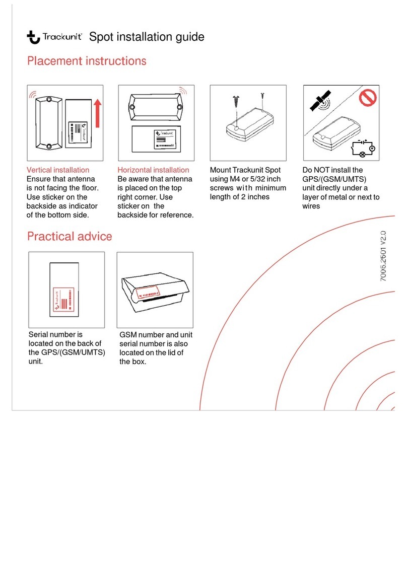
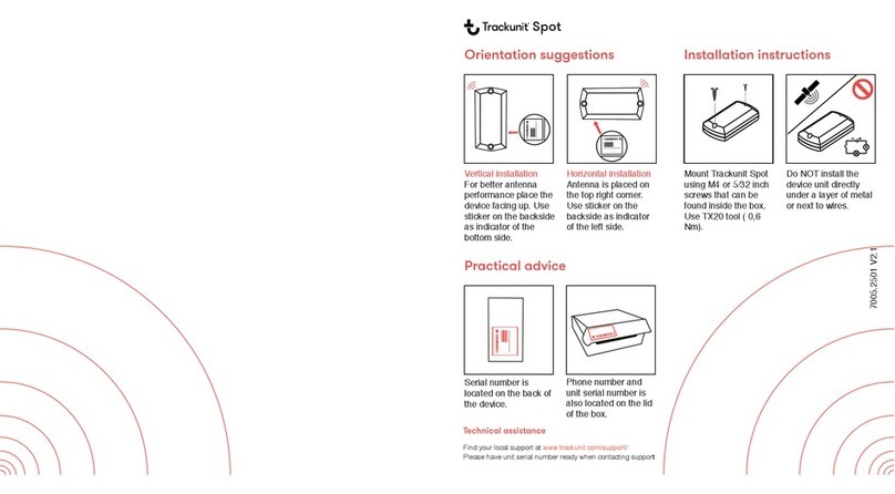
The unit must be mounted either horizontally or vertically (sideways) using either screws or
strips. The unit must not be installed with the interface/supply cable hanging down, as this
will reduce the GPS sensitivity.
Optimize the placement of the unit to increase the aerial view (through windows etc.) as
much as possible. For hiding the unit, make sure it is only mounted beneath plastic parts or
similar parts (wood), but not beneath metal parts.
To reduce hum and noise in the FM radio it is recommended to place the unit at a minimum
distance of 20 inches (50 cm) from the radio or the loudspeakers.
Installation for insurance and anti-theft purpose
For an installation of the TU600-X with respect to insurance coverage of equipment/items/vehicles
etc. in your country/region please contact your nearest sales office for support as the TU600-X
installation must be registered and documented for the local insurance company, the associated
local alarm center.
The installation position in multiple equipment/items/vehicles etc. of the same type must be insured
to be random to increase the theft protection.
It is needed to sign up a different subscription for each installed TU600-X unit under insurance
coverage that covers the local alarm center administration of the units.
The local sales office will be able to inform you about the obligations that you have in relation to the
insurance company and how to act in relation to the alarm center while the units are covered by
the insurance.
The unit must NOT be installed beneath metal plates or
inside closed metal compartments. Incorrect installation will
also reduce the stan
dby time of the battery inside the unit

TU600-X
Trackunit TU600-X, Technical Manual v1.0, December 2019 Page 14
Connections
The connections depend on the type of vehicles / machines etc. in which the (GSM/LTE M1/NB
IOT)/GPS unit is to be installed.
Different variants of the TU600-X device will have only a subset of the connections shown in the
table below. Please contact your nearest sales office, distributor or “Reseller” for further
information about the availability of other variants in your area.
Wire
(co
lor code)
TU600-X function
Red Supply voltage +12V / +24V
White Digital input 1
Brown Digital input 2 (Ignition)
Grey Digital input 3
Yellow Digital output 1
Green 1-Wire input (M8 Connector)
Pink Digital input 4
Orange CAN HI (Optional)
Light Blue CAN LO (Optional)
Blue Common ground
Power supply
The unit must be connected to either +12V, +24V battery voltage through a 1A/32V fuse or +36V,
+48V battery through 3A/80V fuse. The use of a fused supply wire is important for not damaging
the wires related to the unit in case of a short circuit etc.
Digital inputs
The activation of a digital input requires a minimum high-level voltage of 9,5V.
Digital output
The digital output has the type indication” LO-side switch”, that connects the output to 0V “ground”,
when the output is active. This output can be used to control a relay powered from an external DC
supply voltage. The maximum current drawn from the output is 200mA.
The output is protected against short circuits, overload and is also protected against over voltage.
For further information about connection possibilities of the digital output, see chapters about
installation later in this manual.
Motion/acceleration sensor
The unit has a built-in 3 axis acceleration sensor that can activate the unit if it, as a consequence
of disconnected supply voltage, is in stand-by mode (theft protection), log accelerometer data (for
analyzing shock and machine behavior) or configured as a tilt-sensor.
CAN interface
TU600 is equipped with a built-in CAN Controller.
Protocols supported: SAE J1939 and CANopen. The CAN interface is Fully Compliant with CAN
2.0 Part A and 2.0 Part B. 8 independent message objects (mailboxes) are implemented, and

TU600-X
Trackunit TU600-X, Technical Manual v1.0, December 2019 Page 15
Controller supports Bit Rates up to 1 Mbit/s.
Physical Interface specification as referred to by ISO/11898-2. 120R CAN termination optional:
Mounted, Not Mounted or controlled by Firmware (CAN configuration).
The CAN Interface is only operational when supply voltage (12V / 24V / 48V) is present. Interface
cannot operate on internal battery alone.
M8 Connector: 1-Wire input
The M8 3 pole connector contains 3 signals: 1-wire bus, 5V and Ground.
The 1-wire is designed to communicate with Maxim 1-wire parts. Ex. Digital Thermometer
(Temperature logging) or Maxim iButton Keys/tags (Access Control).
The 1-wire input is only operational when supply voltage (12V / 24V / 48V) is present. Interface
cannot operate on internal battery alone.
Installing the TU600-X as to surpass the main switch on the machine.
In case the main switch on the machine will break the negative wire (Ground wire), the inputs may
register a voltage level and start counting operating hours. To avoid this situation the digital input 4
(Pink wire) should be connected to the chassis/ground on the machine. Then send the following
SMS to the unit (phone number) to activate the filtering:
Function
Send S
MS
Return
-
SMS from the unit
Activate filter function on inputs. MT INFILT ON MTC ACK (SERIAL No.) INFILT ON
NOTE: Enabling the filtering function will disable the use of the digital input 4 as a normal input.
NOTE: It is recommended always to connect digital input 2 to the ignition signal of the vehicle
or machine.
NOTE: For the “Send SMS” it is of no importance if small or capital letters are used in the
command string, or a mixture hereof.
Wireless connectivity: Bluetooth LE
The TU600 can operate in Bluetooth LE band for access control, device configuration and assert
tracking.
The TU600 will operate on a BT LE radio wave system when assessed by a paired unit i.e.
cellphone. When connected the cellphone can be used as a mean for access control to the
vehicles, machinery etc. on which the TU600 is physically installed.
In addition to the use case described above the TU600 can also be requested to passive scan for
BLE advertisements and thereby enable assert tracking.

TU600-X
Trackunit TU600-X, Technical Manual v1.0, December 2019 Page 16
Functionality check

TU600-X
Trackunit TU600-X, Technical Manual v1.0, December 2019 Page 17
“Verify my Trackunit”
In order to control if the installation of the TU600-X unit has been done correctly, it is possible to
use the “Verify my Trackunit” tool.

TU600-X
Trackunit TU600-X, Technical Manual v1.0, December 2019 Page 18
Troubleshooting
Various error situations are listed below along with some possible solutions.
Error
code
Error description Possible solutions
F1 The unit does not
answer the SMS
command send to it.
Verify if the SMS messages are sent to the correct GSM/LTE
M1/NB IOT phone number.
Check LED status; See the “Functionality check” chapter in this
manual.
If the TU600-X unit has been delivered with the SIM card
mounted. Contact Trackunit support.
o Or contact the mobile operator to verify if there is
any problem with the SIM card.
Verify if the SIM card is correctly mounted in the unit.
F2 The LED in the unit is
off, thus no power on the
unit.
Check if the installation is performed correctly according to the
guidelines of this manual.
F3 The LED is constant red;
thus the unit is not
attached to the GSM /
LTE network
If the TU600-X unit has been delivered with the SIM card
mounted. Contact Trackunit support.
o Or contact the mobile operator to verify if there is
any problem with the SIM card.
Verify if the SIM card is correctly mounted in the unit.
Verify if the PIN code has been disabled from the SIM card
before it was inserted in the unit
F4 The unit send reply
messages but there is no
GPS signal
Verify if the unit is mounted according to the instructions laid out
in this manual with respect to the aerial view; see “Installing the
unit” chapter.
If the machine/vehicles are located inside a building, please
move the machine/vehicle outside a try again.

TU600-X
Trackunit TU600-X, Technical Manual v1.0, December 2019 Page 19
Installation of the digital output
According to the E1 certificate of the TU600-X unit, it is prohibited under any circumstances to use
this output to control any equipment that may influence the safety of the construction machinery
and earth moving machines/vehicle operation and driving. The output must only be used to control
comfort equipment.
The example shows a
12V relay function with a
12V DC supply voltage. It
is also possible to use a
24V relay with a 24V DC
supply voltage etc. The
current consumption of
the relay must not exceed
200 mA (DC current) and
the relay contacts must
be specified to withstand
the load that needs to be
controlled.
NOTE: The output can only handle DC and not AC voltage. It is necessary to only use a DC
power supply for the relay.
Important! The power supply connected to the TU600-X (GSM/LTE M1/NB IoT)/GPS unit
and the supply voltage for the relay mounted on the digital output must have a
common ground connection.
One application example for the “Usable contact function controlled by the TU600-X” signals
shown in the figure above could be a “Start Relay”, blocking function, for preventing unauthorized
use of the moving machinery and construction machine or vehicle outside normal working hours
etc.

TU600-X
Trackunit TU600-X, Technical Manual v1.0, December 2019 Page 20
SMS commands for output control
Function
Send SMS
Return SMS
Description
Activation of the
output
MT OUT1=ON
MTC ACK (SERIAL
No.) OUT1 ON
With this command the output is activated
permanently. The output can be de-
activated again using the “OFF” command.
Deactivation of
the output
MT OUT1=OFF
MTC ACK (SERIAL
No.) OUT1 OFF
With this command the output is
deactivated.
NOTE: For the “Send SMS” it is of no importance if small or capital letters are used in the
command string, or a mixture hereof.
Safety precautions
The use of the digital output is restricted to signals/systems/components related to
comfort applications in the vehicles.
Under no circumstances must it be used for purposes, which can influence the safety of
the vehicle when driving.
Trackunit holds no liability for any damages occurred to persons, vehicles, moving
machines, construction machines etc. caused by wrong installation and/or faulty use of
the digital output.
Warranty
Trackunit A/S products are covered by a limited manufacturer warranty. The Trackunit A/S
warranty is limited to the warranty rules and legislation present in each country. The warranty only
covers manufacturing faults.
The warranty does not cover misuse, wrong installation or damage due to a faulty installation or
wrong maintenance.
The invoice act as the proof of warranty, so please keep it as reference for any warranty
complaints.
Technical Assistance/Support and spare parts
Trackunit A/S offers technical assistance to all our customers about the use, installation, insurance
and spare parts:
If you have a problem and cannot find the information you need in the product
documentation, please contact Trackunit A/S.
For replacement batteries Trackunit model PN 4233.0002 must be used, please order at
Trackunit A/S.
This manual suits for next models
9
Table of contents
Other Trackunit GPS manuals
