TrackWeight I Series User manual
INSTALLATION MANUAL
SCALES FOR TRUCKS
BRT4 &BRT5
SERIES I
V1.0.0


Installation Manual | V1.0.0 | 3
Table of Contents
TABLE OF CONTENTS...............................................................................................................................3
INTRODUCTION........................................................................................................................................4
MAIN CONFIGURATIONS ..........................................................................................................................5
SEMI-TRAILER................................................................................................................................................ 5
6–10-WHEEL TRUCK.................................................................................................................................... 6
12-WHEEL TRUCK .......................................................................................................................................... 7
INSTALLATION OF THE MONITOR AND COMMUNICATION BOX................................................................8
COMPONENTS................................................................................................................................................ 8
INSTALLATION ................................................................................................................................................ 9
INSTALLATION OF AIR SENSOR ON TRAILER OR 6 - 10 - 12-WHEEL TRUCKS .......................................11
COMPONENTS..............................................................................................................................................11
ADDITIONAL COMPONENTS (TRACTOR-TRAILER).................................................................................................12
INSTALLATION ON TRACTOR-TRAILER CONFIGURATION ........................................................................................13
Tractor end..........................................................................................................................................13
Trailer end ...........................................................................................................................................15
INSTALLATION ON 6-10 -12-WHEEL TRUCK CONFIGURATION............................................................................16
INSTALLING A MECHANICAL RT SENSOR ..............................................................................................17
COMPONENTS..............................................................................................................................................17
INSTALLATION ..............................................................................................................................................18
APPENDIX 1-MATCHING OF RT SENSOR SIGNALS ............................................................................................25
APPENDIX 2-RUSTPROOF WELD PROCEDURES ..............................................................................................26
INSTALLATION OF OPTIONAL ACCESSORIES..........................................................................................27
EXTERIOR LIGHTS/ALARMS (BRT 620-M, BRT 622) .....................................................................................27
IMPRIMANTE (BRT 504) ..............................................................................................................................28
CONTACT US ..........................................................................................................................................29
UPDATE NOTES......................................................................................................................................30

Installation Manual | V1.0.0 | 4
Introduction
Thank you for purchasing a high-precision electronic scale from TrackWeight. Based on more
than 20 years of expertise, research and development, your weighing system will provide you
with years of service and precision, under the most difficult road or construction conditions.
The durability and performance of your BRT system is closely linked to a quality installation
and precise calibration. To do this, your authorized reseller will be able to adjust your
TrackWeight scale according to your needs. If you do the installation yourself, no problem.
Consult this installation manual to guide you step by step. Then flip through your user
manual as it contains all the information you need to set up, calibrate and use your scale.
RMT Equipment is the exclusive distributor of TrackWeight products in Quebec, and
distributes a wide range of weighing systems and reversing cameras. For technical
assistance during installation, please contact the Service department at 1-877-663-4311 or
visit the www.rmtequip.com website.
Once again, congratulations and happy driving with your TrackWeight system!
Installation Manual | V1.0.0 | 5
Main configurations
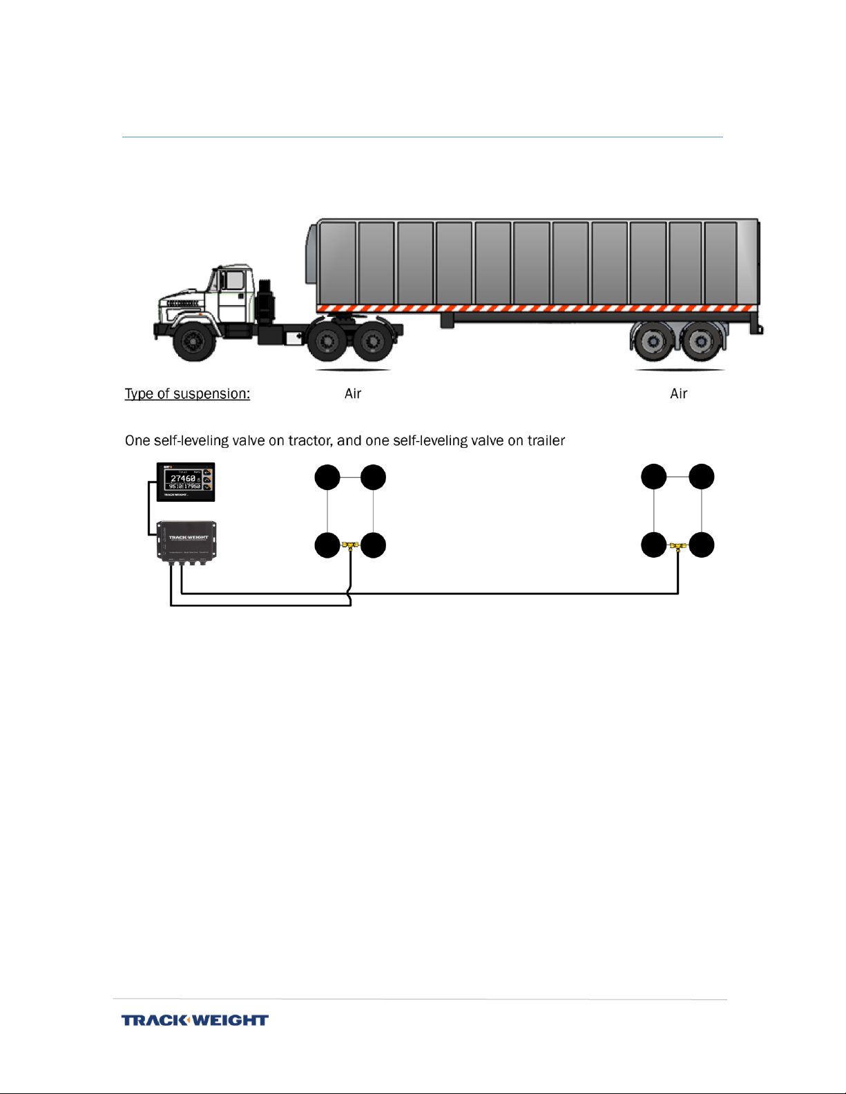
Semi-trailer
Installation Manual | V1.0.0 | 6
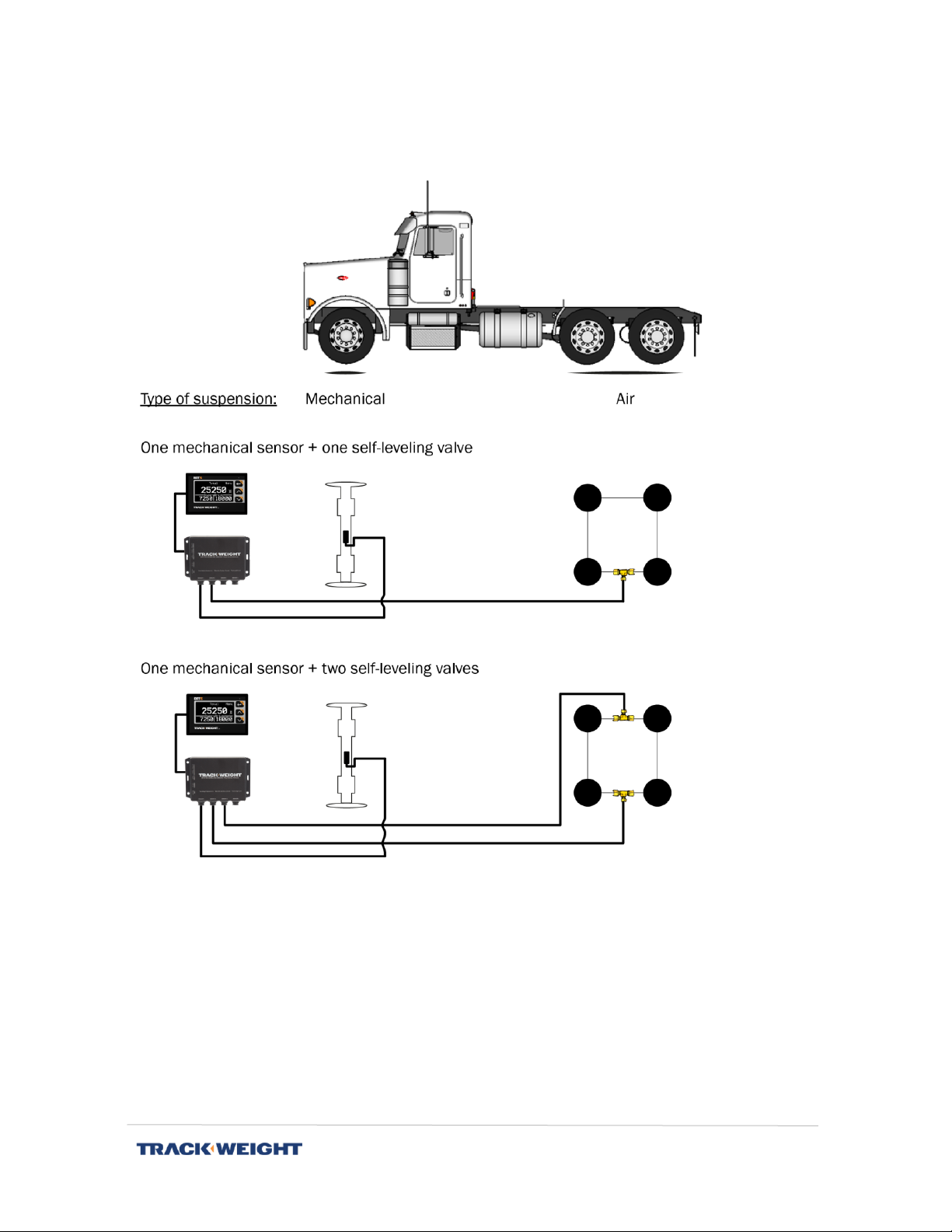
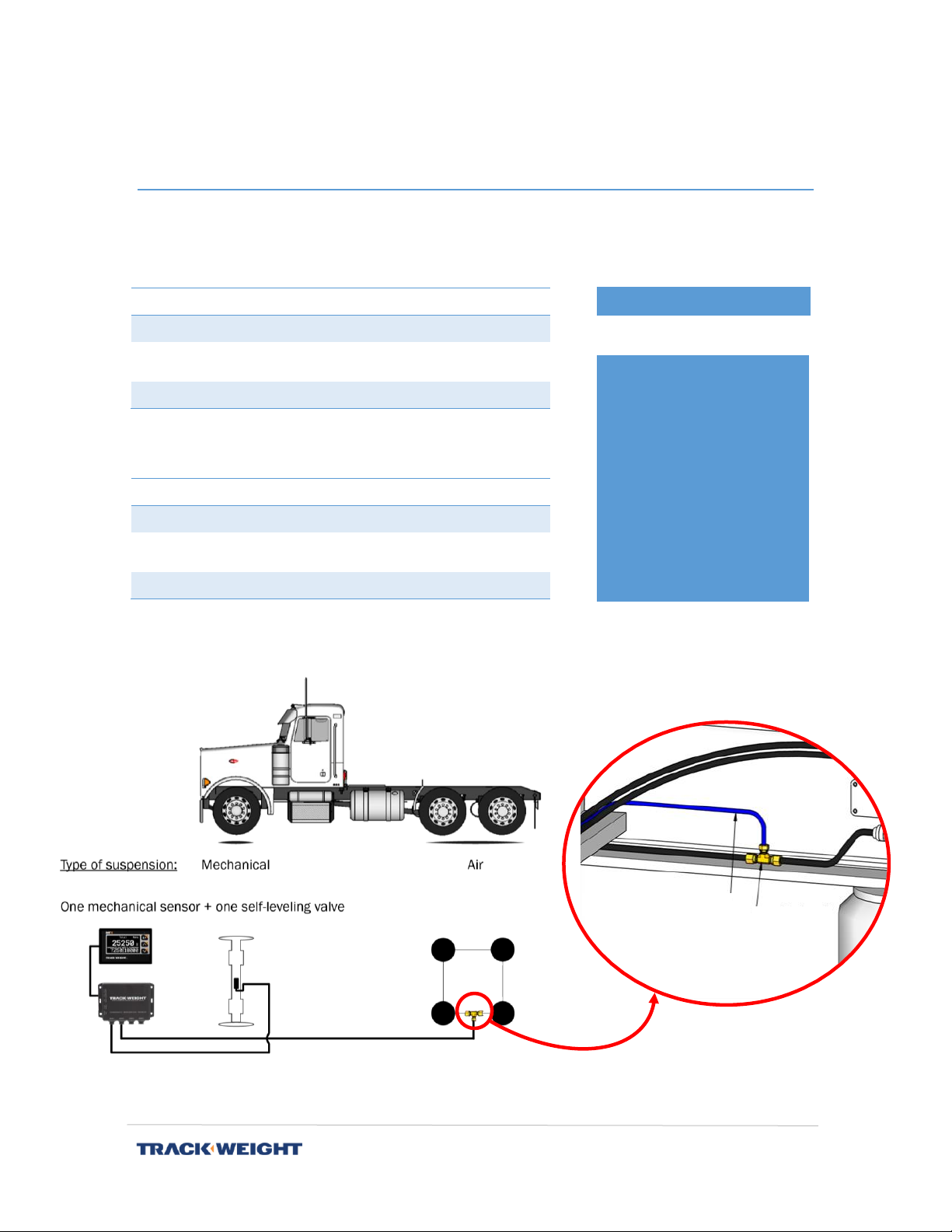
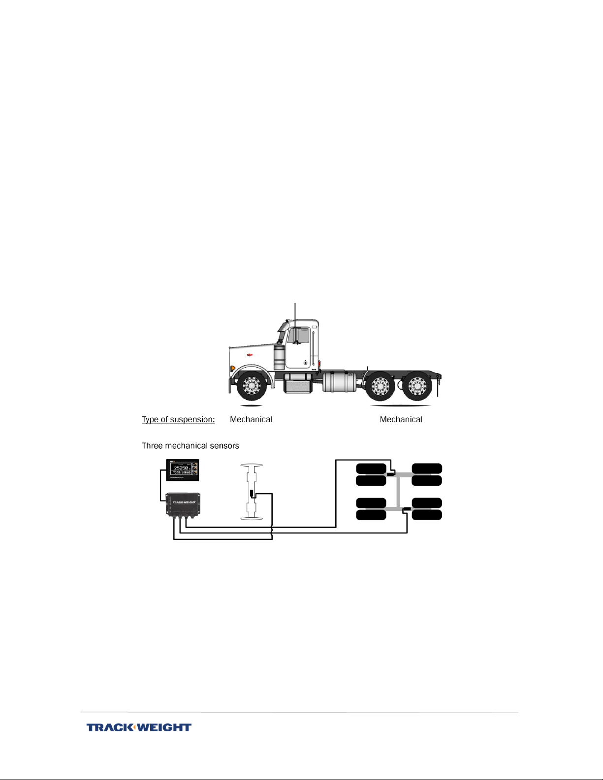
6 –10-wheel truck
Installation Manual | V1.0.0 | 7
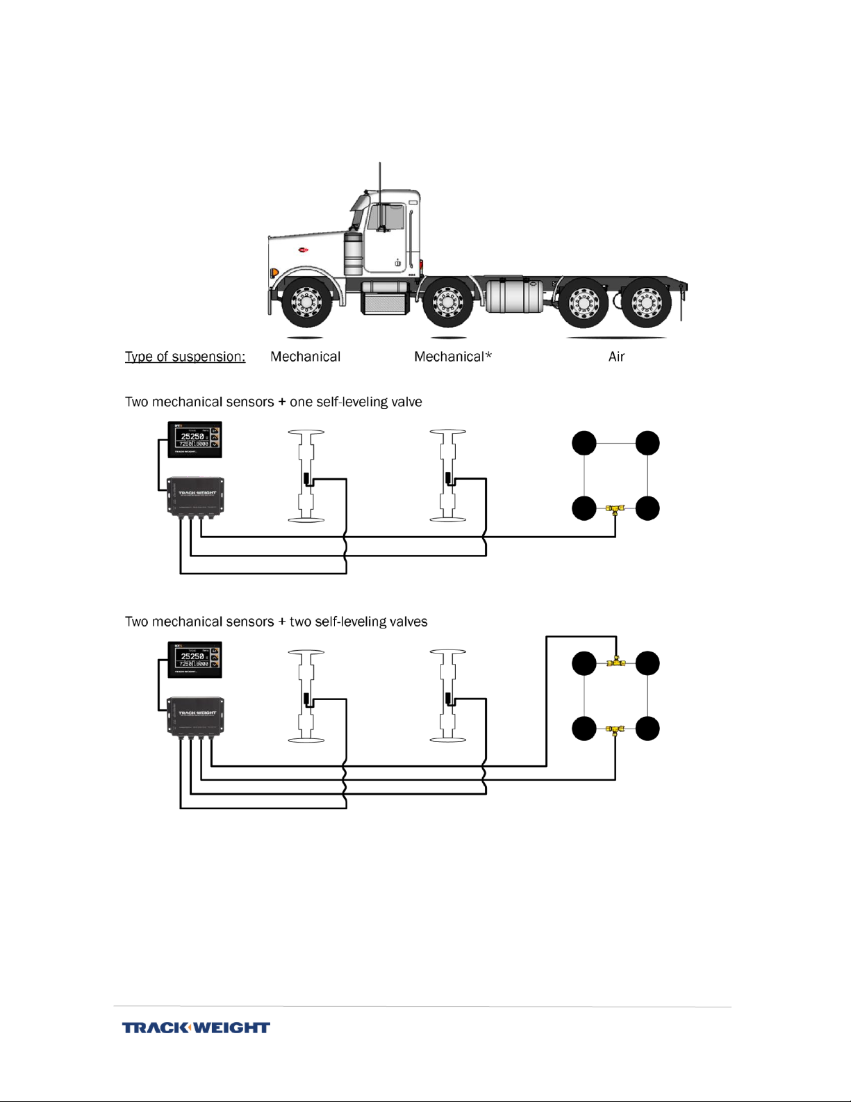
12-wheel truck
* If it is a lift axle, it is possible to replace the mechanical sensor with an air sensor
depending on the type of suspension.

Installation Manual | V1.0.0 | 8
Installation of the monitor and communication
box
Components
No.
Quantity
Part Number
Component
1
1
BRT 6299 (or BRT 6298)
BRT 5 Monitor (or BRT 4)
2
1
BRT 5300
Communication Box
3
1
BRT 5137
Power cable
4
1
BRT 5136 (or BRT 5138)
BRT 5 monitor cable (or BRT 4
Monitor cable)
1
1
2
3
4
4
Installation Manual | V1.0.0 | 9
Installation
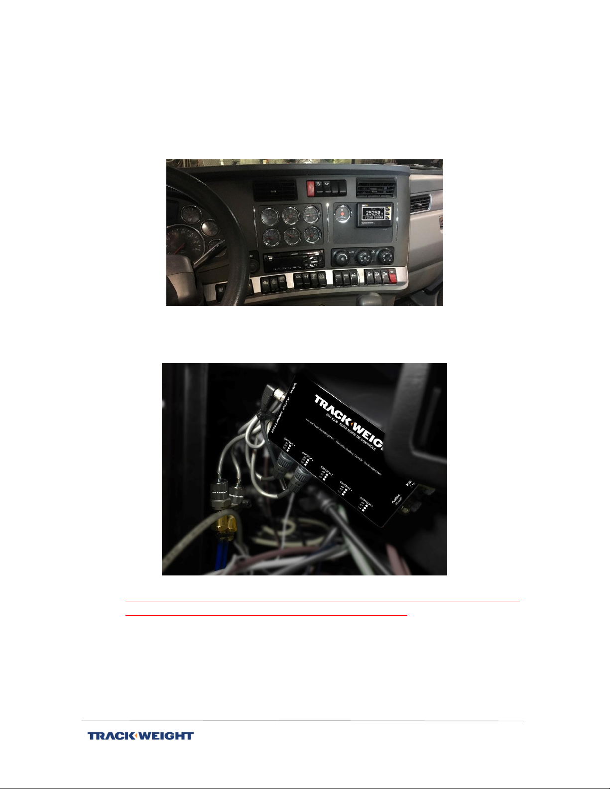
1. Identify a location with enough space to accommodate the BRT 4/5 monitor.
Note: It is possible to install the monitor in the dashboard or on the top of the
dashboard with the stand.
2. The communication box is located inside the dashboard. You must select a location to
protect it with enough space to allow the installation of sensors and cabling.
CAUTION: Avoid installing the communication box near an extreme heat source.
Ideally, it should also be installed far from the radio antenna.
3. Secure the communication box inside the dashboard so that it does not move.

Installation Manual | V1.0.0 | 10
4. The communication box operates on a current of 12-24 VDC. Connect the power cable
(BRT 5137) to the fuse board. The red wire must be connected to a stable source with
a free fuse (minimum 5A). The black wire must be added to the board's common
neutral (or other neutral) for the scale monitor only. The other end of the cable should
be lead to the communication box in the "Power 12-24 VDC" indicated connector.
5. Connect the cable (BRT 5136) to the monitor and to the "Monitor" connector of the
communication box.
Installation Manual | V1.0.0 | 11
- Monkey wrench
o9/16
o1/2
o5/8
- Pliers
- Pipe cutter
- Teflon
- Self-locking tie wraps
REQUIRED TOOLS
Installation of air sensor on trailer or 6 - 10 - 12-
wheel trucks
Components
If one height valve:
Quantity
Part Number
Component
1
BRT 560
Air Sensor
1
BRT 5053 (or BRT
5055)
¼’’ T-tube fitting (or ⅜’’
x ⅜’’ x ¼’’ tube)
BRT 5220
¼’’ tube
If two height valves:
Quantity
Part Number
Component
2
BRT 560
Air Sensor
2
BRT 5053 (or BRT
5055)
¼’’ T-tube fitting (or ⅜’’
x ⅜’’ x ¼’’ tube)
BRT 5220
¼’’ tube
*Recommendation: Hadley series 500 high speed valve.
For installation of a mechanical sensor, see p. 17.
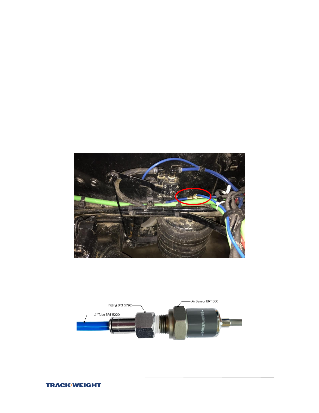
Line towards the air
sensor (¼’’ tube)
T fitting
Raccord
en T

Installation Manual | V1.0.0 | 12
Additional components (tractor-trailer)
In addition to the components listed above, you should have at least one of these
components for installing an air sensor on tractor-trailer configurations.
Quantity
Part Number
Component
BRT 580
Twisted air hose with service hand
BRT 582
⅜ '' air hose with service hand
BRT 584
Service hand with valve
BRT 586
Twisted air hose with ½'' quick plug
BRT 587
Straight air hose with ½'' quick plug
BRT 589
½'' quick plug trailer side
BRT 584
BRT 580

Installation Manual | V1.0.0 | 13
Installation on tractor-trailer configuration
Tractor end
Four air hose options are available: BRT 580 (twisted), BRT 582 (straight), BRT 586 (twisted,
quick plug) or BRT 587 (straight, quick plug).
1. Identify the number of height valves on the tractor.
2. For each system controlled by a valve, an air line must lead to the TrackWeight
communication box.
3. Cut the air line as close as possible to the balloon to insert a BRT 5053 or BRT 5055
"T" fitting
1
(depends on the size of the air line tube).
Note: If the system is controlled by a single height valve and a dial already indicates
the air pressure, it is possible to connect to this pressure indicator in the cab.
4. Insert the cut air line and the ¼" BRT 5220 tube into the "T" fitting and lead this tube
to the front of the tractor in the cab.
5. Insert the BRT 5220 tube into the BRT 5792 fitting and route this tube to the BRT
560 air sensor, installed in the cab, to connect them together.
Note: To ensure a seal between fittings, use teflon.
Note: Make sure that the sensor is installed vertically, downwards, to prevent water
or condensation from accumulating in the sensor and damaging it.
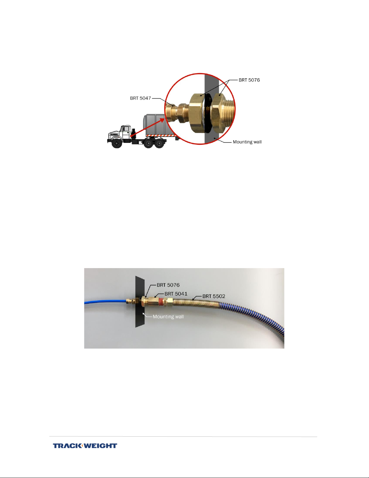
6. Assemble BRT 5047 with BRT 5076 component as shown below.
7. Make a 1-in. diametre hole in the mounting wall.
1
For a group of 3 axles, insert the "T" on the middle one. For a group of 2 axles, insert the "T" on the
one at the back.
Installation Manual | V1.0.0 | 14
8. Insert the assembly made in Step 6 into the hole from the outside and from the side
of the BRT 5076 (the part on the side of the BRT 5047 part on the front side of the
truck).
9. Secure everything from the inside with the washer and nut from the BRT 5076
component.
10. Insert the BRT 5220 tube into the BRT 5047 component and route this tube to the
BRT 560 air sensor to connect them together.
11. Connect all BRT 560 air sensors to the communication box on the inputs. It is
important to identify the lines in order to properly configure the inputs in the
communication box afterwards.
12. On the outside, screw component BRT 5041 to part BRT 5076 and connect the right
(longest) side of the BRT 5502 twisted air hose.
13. On the other side of the BRT 5502 air hose (the side closest to the spirals), connect
the BRT 5556 service hand.
Installation Manual | V1.0.0 | 15
Trailer end
14. Identify the number of height valves on the trailer.
15. For each system controlled by a valve, an air line must lead to the TrackWeight
communication box.
16. Cut the air line as close as possible to the balloon to insert a BRT 5053 or BRT 5055
"T" fitting
2
(depending on the size of the air line tube).
17. Insert the cut air line and ¼ "BRT 5220 tube into the" T "fitting and lead this tube to
the front of the trailer.
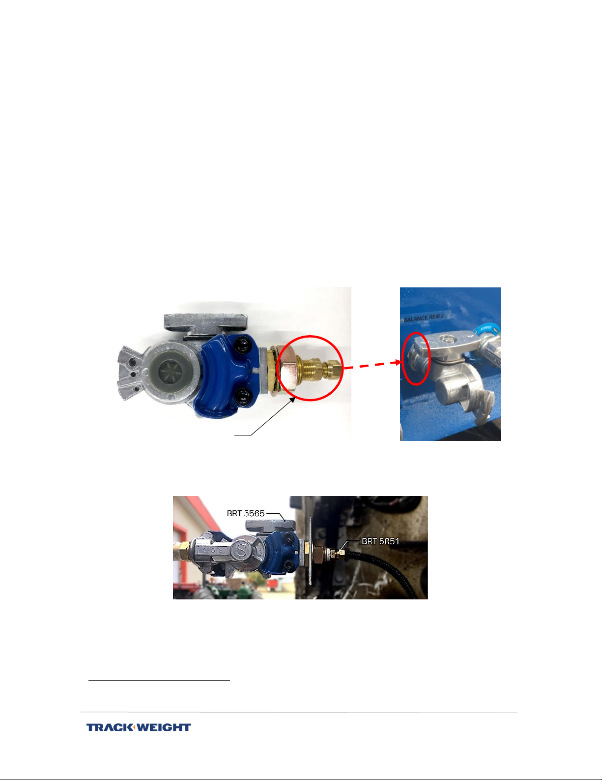
18. Make a 1-in. diameter hole in the mounting wall to insert the BRT 5565 service hand
with valve.
19. Insert the BRT 5051 fitting into the BRT 5565 valve and insert the BRT 5220 tube
into the fitting.
20. Attach valve BRT 5565 and service hand BRT 5556 together.
Note: The air line is closed when the handle of the BRT 5565 valve is perpendicular (as
shown in Step 18, right picture).
2
For a group of 3 axles, insert the "T" on the middle one. For a group of 2 axles, insert the "T" on the
one at the back.
Part to insert only BRT 5051
BRT 5565
Installation Manual | V1.0.0 | 16
Installation on 6 - 10 - 12-wheel truck configuration
1. Identify the number of height valves on the truck.
2. For each system controlled by a valve, an air line must lead to the TrackWeight
communication box.
3. Cut the air line as close as possible to the balloon to insert a BRT 5053 or BRT 5055
"T" fitting (depending on the size of the air line tube) on each group of balloons
controlled by a valve.
Note: If the system is controlled by a single height valve and a dial already indicates
the air pressure, it is possible to connect to this pressure indicator in the cab.
4. Insert the cut air line and ¼" BRT 5220 tube into the "T" fitting and lead this tube to
the front of the truck.
5. Insert the BRT 5220 tube into the BRT 5792 fitting to connect it to the BRT 560 air
sensor, installed in the cab, to then connect the same sensor to the communication
box. Identify the lines in order to properly configure the inputs in the communication
box afterwards.
Note: Make sure that the sensor is installed vertically, downwards, to prevent water
or condensation from accumulating in the sensor and damaging it.
Installation Manual | V1.0.0 | 17
- Two metal clamps (between
12'' and 18'')
- Small mass
- ⅜ratchet wrench with 9/16
short and 7/16 long sockets
- Rod or welding rod 7018
- Measuring tape
- Marking pen for use on metal
- Angle grinder with grinding
disc (¼)
- Pre-cut, adjustable, metal
bracket
- Blue anti-seize or Locktite
- Black enamel paint (quick dry)
- Self-locking tie wraps
REQUIRED TOOLS
Installing a mechanical RT sensor
Components
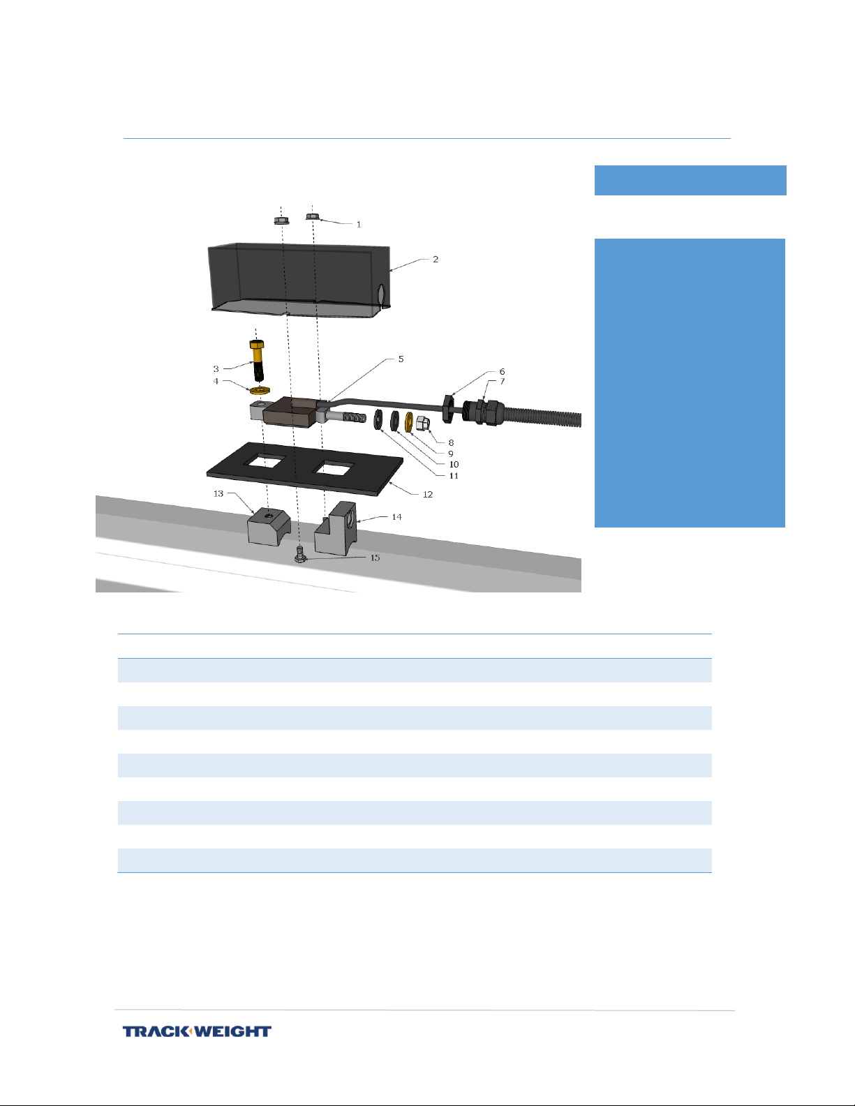
* Optional stainless steel component available.
No.
Quantity
Part No.
Component
1-2-15
1
BRT 5699 *
Aluminum lid with bolts and nuts
3
1
BRT 5085
⅜-24 x 1-½'' bolts
4-9
2
BRT 5078
⅜ Washer
5
1
BRT 550-XX
RT sensor
6-7
1
Cable tie
8
1
BRT 5077
⅜-24 locking nut
10-11
1
BRT 5722
⅜ Alignment washers (concave and convex)
12
1
BRT 5110
Foam for sensor
13-14
1
BRT 600-AC *
Set of steel blocks
Installation Manual | V1.0.0 | 18
Installation
1. Determine the correct location for sensor installation.
Note: Make sure that the RT sensor does not interfere with fixed or moving parts of
the vehicle.
›For the front axle(s): Ideally in the center of the axle. However, be sure to check
the clearance of the truck and have a good clearance (with the protective
cover) so that the sensor does not catch on the oil pan or any other part of the
truck.
›For rear axles: Place the sensors in opposite positions, ideally centered
between the "bushing" and the wheel. Make sure there is at least 10 cm
clearance between the sensor and the wheel. The sensor on the driver's side
must be on the back of the axle and the one on the passenger side must be on
the front of the rear axle group.
2. Prepare the "beam" structure for welding by removing any paint, rust and/or other
potential contaminants.
Installation Manual | V1.0.0 | 19
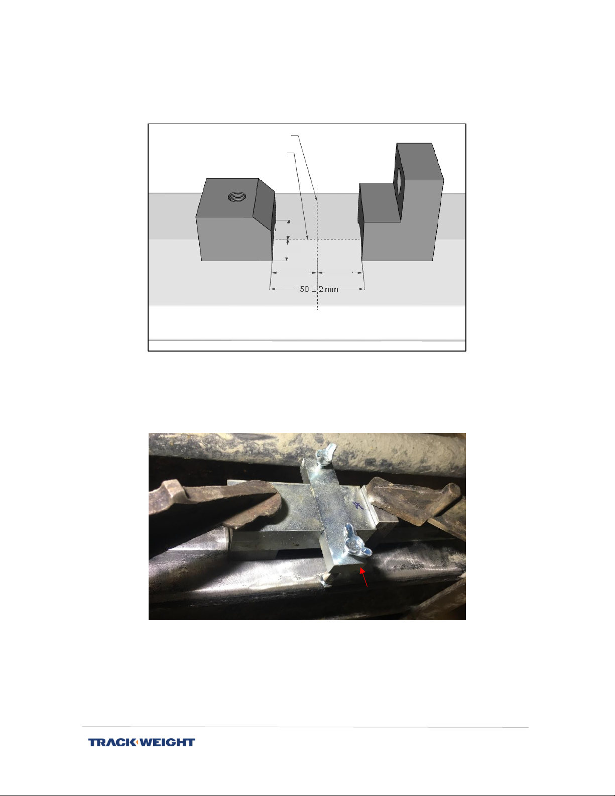
3. Place the fixed and adjustment block at the center of the width of the chosen
location on the structure (axis or "beam"). The blocks should be placed face-to-face
within 50 ± 2 mm of each other.
Note: If you have the BRT9081 installation assistance tool, you only need to make
sure you find the center of the beam width and check the clearance.
4. Use pliers to hold the blocks in place before welding.
5. Preheat around blocks up to 65 ° C.
6. "Stop" each outside corner of the two blocks to the structure. See Figure p. 20.
IMPORTANT: The use of the welding rod or 309L-16 wire, rustproofing, or 7018,
steel, is mandatory. See Appendix 2 for rustproofing weld procedures
BRT9081 installation
assistance tool
Section to be measured
Centre of the section to
be measured
Centre
Centre
Centre
Centre
Installation Manual | V1.0.0 | 20
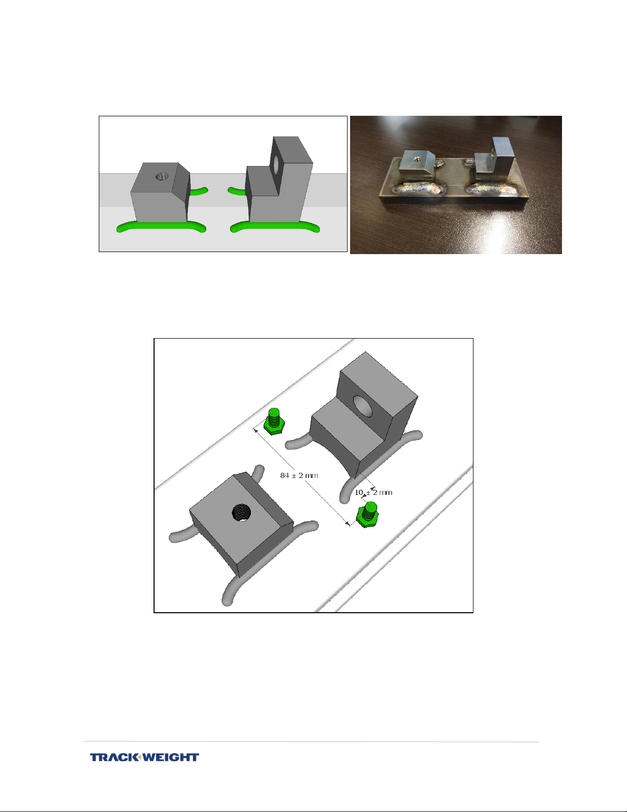
7. Make a weld in 3 passes on each side of the two blocks. The weld must exceed the
blocks by at least 15 mm.
8. Vertically weld 2 ¼-20 x ½" steel bolts (or rustproofing, depending on option
purchased) at the position shown in the image below.
9. Hide threads (stationary block and bolts) and apply rustproof black paint while axle
and blocks are still hot.
Example
This manual suits for next models
4
Table of contents
Other TrackWeight Accessories manuals


