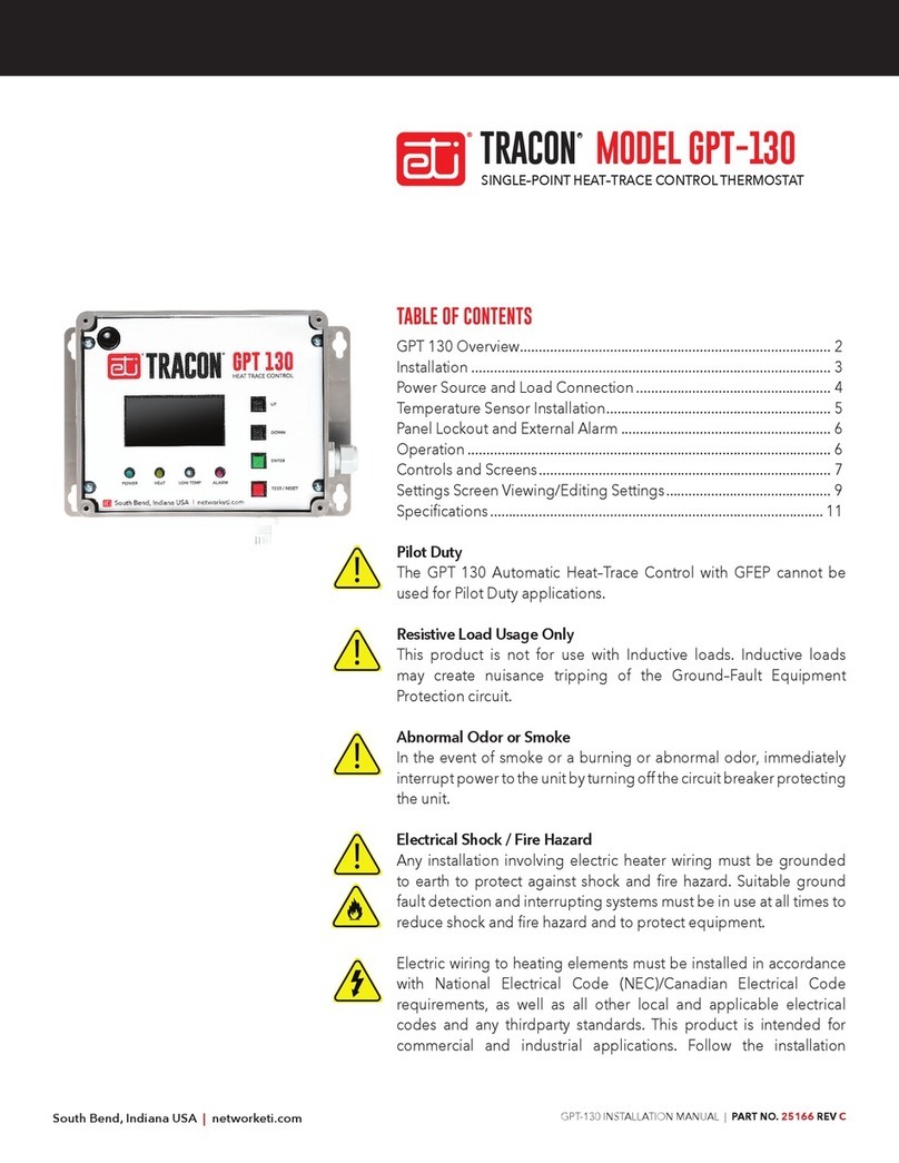
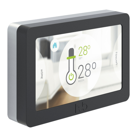
Tracon GPT-130 Instruction Manual

GPT-130 INSTALLATION MANUAL | PART NO. 25166 REV E
TABLE OF CONTENTS
GPT 130 Overview................................................................................... 2
Installation ................................................................................................ 3
Power Source and Load Connection .................................................... 4
Temperature Sensor Installation............................................................ 5
Panel Lockout and External Alarm ........................................................ 6
Operation ................................................................................................. 6
Controls and Screens.............................................................................. 7
Settings Screen Viewing/Editing Settings............................................ 9
6SHFLƓFDWLRQV ......................................................................................... 11
Pilot Duty
The GPT 130 Automatic Heat–Trace Control with GFEP cannot be
used for Pilot Duty applications.
Devoir du pilote
Le GPT 130 Automatic Heat – Trace Control with GFEP ne peut pas
être utilisé pour les applications Pilot Duty
Resistive Load Usage Only
This product is not for use with Inductive loads. Inductive loads may
create nuisance tripping of the Ground–Fault Equipment Protection
circuit.
Utilisation de charge résistive uniquement
Ce produit n’est pas destiné à être utilisé avec des charges inductives.
Les charges inductives peuvent créer un déclenchement intempestif
du circuit de protection de l’équipement contre les défauts à la terre.
Abnormal Odor or Smoke
In the event of smoke or a burning or abnormal odor, immediately
interrupt power to the unit by turning off the circuit breaker protecting
the unit.
MODEL GPT-130TRACON
®
SINGLE–POINT HEAT–TRACE CONTROL THERMOSTAT
Heat Tracing Sales Mt. Airy, MD (410) 795-2223 www.heattracingsales.com
Heat Tracing Sales Mt. Airy, MD (410) 795-2223 www.heattracingsales.com

GPT-130 INSTALLATION MANUAL | PART NO. 25166 REV E
2
Odeur ou fumée anormale
En cas de fumée ou de brûlure ou d’odeur anormale,
coupez immédiatement l’alimentation de l’unité en
fermant le disjoncteur protégeant l’unité.
Electrical Shock / Fire Hazard
Any installation involving electric heater wiring must
EH JURXQGHG WR HDUWK WR SURWHFW DJDLQVW VKRFN DQG ƓUH
hazard. Suitable ground fault detection and interrupting
V\VWHPVPXVWDOZD\VEHLQXVHWRUHGXFHVKRFNDQGƓUH
hazard and to protect equipment.
Electric wiring to heating elements must be installed
in accordance with National Electrical Code (NEC)/
Canadian Electrical Code requirements, as well as all other
local and applicable electrical codes and any third-party
standards. This product is intended for commercial and
industrial applications. Follow the installation instructions
contained in this manual and those provided by the
heater manufacturer.
Size the circuit breaker appropriately for the expected
load and inrush current. The maximum rated current for
the GPT 130 is 30 amps with resistive load.
Heater loads and their controls should not share a circuit
branch with other types of equipment. A shared circuit
may result in electromagnetic interference that can affect
system operation. Make certain that the heater shield is
properly grounded. Failure to do so may result in damage
WRWKHHTXLSPHQWRUƓUH
Following installation and prior to beginning system
operation, refer to and perform the Post-Installation Test
described in this manual.
Risque de choc électrique / d’incendie
Toute installation impliquant un câblage de chauffage
électrique doit être mise à la terre pour se protéger
contre les chocs et les risques d’incendie. Des systèmes
appropriés de détection et d’interruption des défauts à la
terre doivent toujours être utilisés pour réduire les risques
de choc et d’incendie et protéger l’équipement.
Le câblage électrique des éléments chauffants doit être
installé conformément aux exigences du Code national
de l’électricité (NEC) / du Code canadien de l’électricité,
ainsi qu’à tous les autres codes électriques locaux et
applicables et à toute norme tierce. Ce produit est destiné
à applications commerciales et industrielles. Suivez les
instructions d’installation contenues dans ce manuel et
celles fournies par le fabricant de l’appareil de chauffage.
Dimensionnez le disjoncteur en fonction de la charge
et du courant d’appel attendus. Le courant nominal
maximum pour le GPT 130 est de 30 ampères avec une
charge résistive.
Les charges de chauffage et leurs commandes ne doivent
pas partager une branche de circuit avec d’autres types
d’équipement. Un circuit partagé peut entraîner des
interférences électromagnétiques qui peuvent affecter
opération Système. Assurez-vous que le blindage du
radiateur est correctement mis à la terre. Ne pas le
faire peut endommager l’équipement ou provoquer un
incendie.
Après l’installation et avant de commencer le
fonctionnement du système, reportez-vous et effectuez le
test de post-installation décrit dans ce manuel.
ITEMS INCLUDED
QTY. P/N DESCRIPTION
1 25170 TRACON MODEL GPT 130
Single-Point General Purpose
Heat–Trace Control
1 25076 Temperature Sensor
1 25299 GPT 130 Installation Sheet
OVERVIEW
TheTRACON GPT130 Heat–Trace Control is a single–point
microprocessor–based heat–trace control thermostat.
It is ideal for applications which require Ground–Fault
Equipment Protection (GFEP). Ideal uses include freeze
Heat Tracing Sales Mt. Airy, MD (410) 795-2223 www.heattracingsales.com
Heat Tracing Sales Mt. Airy, MD (410) 795-2223 www.heattracingsales.com

GPT-130 INSTALLATION MANUAL | PART NO. 25166 REV E
3
protection, hot water temperature maintenance, grease
line trace,tank heating, and other temperature monitoring
and control applications. The GPT 130 and its heater load
can operate with an available line voltage source of 100
– 277 V ac. The controller and heater load share the same
supply connection. The internal load contactor is rated to
switch up to 30 A resistive. The Integral GFEP provides
safety in compliance with national and local electrical
codes. The unit’s housing is a NEMA 4X IP66 weather–
resistant enclosure for enhanced durability.
FEATURES AND BENEFITS
• Adjustable temperature setpoint allows precise control
of a wide range of processes
• Can use an NEC Class 2 temperature sensor with up to
2,000 ft. cable for enhanced installation options
• Thermistor temperature sensor with 20 ft.cable included
IRUDSSOLFDWLRQVRIŧr)WRr)ŧr&WRr&
• RTD input allows higher accuracy and extreme–
temperature applications
• The unit can accommodate RTD sensors with 3–wire
FRQƓJXUDWLRQ
• Temperature display for accurate adjusting and
monitoring
• Load current display for accurate adjusting and
monitoring
• Ground fault current display for accurate monitoring,
protection, and alarm
• Adjustable alarm thresholds for excess ground fault
current, load current, and temperature
• Alarms indicated with panel display and relay contact
for remote signaling
• A Fault Mode setting which can be set to energize or de-
energize the heaters during a sensor failure
• Fire Protection Mode maintains heater operation for use
LQFULWLFDOƓUHSURWHFWLRQV\VWHPV
• Durable weather–resistant NEMA 4X IP66 enclosure
permits indoor or outdoor installation
The GPT 130 is permanently connected equipment and
does not have an internal disconnect device. The
installer must provide an accessible disconnect device,
with short circuit and overcurrent protection (these are
not supplied by Environmental Technology Inc). When
power is applied, the system will start.
Heat Tracin
g
Sales Mt. Air
y
, MD
(
410
)
795-2223 www.heattracin
g
sales.com
Heat Tracin
g
Sales Mt. Air
y
, MD
(
410
)
795-2223 www.heattracin
g
sales.com

GPT-130 INSTALLATION MANUAL | PART NO. 25166 REV E
4
INSTALLATION
The GPT 130 Automatic Heat–Trace Control should be
LQVWDOOHG E\ D TXDOLƓHG OLFHQVHG HOHFWULFLDQ ,QVWDOODWLRQ
must conform to all applicable local and national electrical
codes and laws. The unit’s NEMA 4X IP66 enclosure allows
for indoor or outdoor applications.
The GPT 130 controller has an ambient operating
WHPSHUDWXUHUDQJHRIŧr)WRr)ŧr&WRr&
To avoid potential internal condensation mount the unit
out of direct sunlight.
,QVWDOO WKH *37 RQ D Ɠ[HG ŴDW YHUWLFDO VXUIDFH XVLQJ
WKH XQLWōV PRXQWLQJ ŴDQJHV 7KH PRXQWLQJ ŴDQJHV
accommodate 1/4” or 6.3 mm fasteners.
The GPT 130’s nonmetallic enclosure has one 1.046” hole
for conduit entry; this can hold both power andload wiring.
Use only Listed Type 4X IP66 liquid–tight conduit hubs
or cable glands. Connect the hub to the conduit system
before connecting the hub to the enclosure.
The unit comes with two installed liquid–tight cable
JODQGV2QHRIWKHVHƓWWLQJVLVIRUWKHWHPSHUDWXUHVHQVRU
cable, and the other is for the alarm relay cable.
The cable glands can accommodate cable diameters
0.08” to 0.24” (2 mm to 6 mm). The temperature sensor
may be located up to 2,000’ (610m) from the GPT.
There is a removable electrical insulation divider that
must be in place when there is power applied to the unit.
All leads should be terminated; no unsecured leads
should be left inside the wiring compartment.
JP1
JP2
FPT130
Thermistor
Fault FPT130
Set
Point
GPT
Heat On
Fire Prot Lock
Heat Off
1
01
1
0
0
1
0
0
1
50F
45F
30F
38F
INPUT POWER HEATER CABLE
TEMPERATURE SENSOR
ALARM RELAY
Figure 1
Line:
Neutral:
Ground:
Line:
Neutral:
Ground:
Thermistor
RTD 3-wire
The GPT 130 wiring layout
BLACK / Line 1
WHITE / Line 2
GREEN
BLACK / Line 1
WHITE / Line 2
GREEN
Heat Tracin
g
Sales Mt. Air
y
, MD
(
410
)
795-2223 www.heattracin
g
sales.com
Heat Tracin
g
Sales Mt. Air
y
, MD
(
410
)
795-2223 www.heattracin
g
sales.com

GPT-130 INSTALLATION MANUAL | PART NO. 25166 REV E
5
Copyright © 2019 ETI.
®
All rights reserved.
POWER SOURCE AND CONTACTOR CONNECTIONS
Supply Voltage
The GPT 130 operates from 100 – 277 V ac at 50/60
Hz. This control and its heater load should not share a
circuit branch and circuit breaker with other types of
equipment.A shared circuit may result in electromagnetic
interference that can affect system operation. For line
supply and load connections, use 10 AWG wires rated
IRUDWOHDVWr)r&7KHFRQQHFWLRQVDUHVKRZQLQ
Figure 3 and Figure 4.
Contactor Ratings
The heater contactor provides two (2) Form A (DPST)
contacts rated for heater loads up to 30 A ac and 277 V ac.
These two contacts are used to control both legs of the
input power (Line and Neutral).
Manual Load Test
To manually energize the load, select the Settings screen
DQG WKHQ KROG 7HVW5HVHW SXVKEXWWRQ IRU ƓYH VHFRQGV
7KHRXWSXWZLOOVZLWFKRQDQGVWD\RQIRUƓYHPLQXWHVRU
until Test/Reset key is pressed again. A manual load test is
recommended upon installation to verify heater function
and load current.
FIGURE 2. Mounting Dimensions
FIGURE 3. Contractor Connections
FIGURE 4. Connection Schematic
0
8mm)
1/4"
20' 6"
Sensor Cable
(189mm)
7 7/16"
1.046"
(25.4mm)
o
nduit Entry
Alarm Cable
UP
DOWN
ENTER
GPT 130
HEAT TRACE CONTROL
POWER HEAT LOW TEMP ALARM
TEST / RESET
BACK
NOTE: Cover screws maximum torque: 4 In-Lbs.
Heat Tracin
g
Sales Mt. Air
y
, MD
(
410
)
795-2223 www.heattracin
g
sales.com
Heat Tracin
g
Sales Mt. Air
y
, MD
(
410
)
795-2223 www.heattracin
g
sales.com

GPT-130 INSTALLATION MANUAL | PART NO. 25166 REV E
6
TEMPERATURE SENSOR
The GPT 130 can use either a thermistor (provided), or
a 3–wire RTD sensor.
Thermistor (25076)
The GPT 130 comes with a thermistor temperature sensor
with a 20 ft. jacketed cable that has an operating range
RIŧr)WRr)ŧņ&WRņ&6HH)LJXUHIRU
proper wiring when using a thermistor sensor.
RTD
The unit can use an RTD sensor for applications requiring
a wider temperature range. The GPT 130 can operate
with 3–wire RTD sensors . See Figure 5 for proper
wiring ZKHQXVLQJDŊZLUH57'sensor.
Note: The sensor must be selected in the Sensor Type
parameter setting screen.
FIGURE 5. STD !e%)*$ W#$#%&
T0e The$/#),*$ #%-., w#$#%&
Heat Tracin
g
Sales Mt. Air
y
, MD
(
410
)
795-2223 www.heattracin
g
sales.com
Heat Tracin
g
Sales Mt. Air
y
, MD
(
410
)
795-2223 www.heattracin
g
sales.com

GPT-130 INSTALLATION MANUAL | PART NO. 25166 REV E
7
PANEL LOCKOUT
To prevent unauthorized changes of control settings, the
second DIP switch can be set to the on position to Lock
the settings. With Lock enabled, the control panel will
allow viewing but not changing any of the settings; only
WKHr&RUr)RSWLRQFDQEHFKDQJHG6HH)LJXUH
Note: The GPT reads the Lock DIP switch position when
the Settings screen is entered. If the switch is changed,
you need to re-enter the Settings screen.
EXTERNAL ALARM
Alarm Connections
An alarm or power–off condition can be communicated
by either opening or closing a relay contact. It is important
to make the proper alarm relay connections to achieve
the desired result. The middle terminal labeled COM
&RPPRQLVXVHGLQERWKZLULQJFRQƓJXUDWLRQV&RQQHFW
one alarm relay lead to the COM terminal.
If the system needs a contact to close to signal an alarm or
power–off condition, connect the other alarm relay lead
to the NC (Normally Closed) terminal. See Figure 7.
If the system needs a contact to open to signal an alarm
or power–off condition, then connect the other alarm
relay lead to the NO (Normally Open) terminal.
If the unit has power, and there are no alarm conditions
then the NO and COM terminals will be connected. If the
unit loses power or an alarm condition occurs then the
NC and COM terminals will be connected.
Note: The “Normally” condition of the relay is the alarm
condition for the unit.
OPERATION
The GPT 130 can maintain temperatures from a setpoint
UDQJLQJIURPŧr)WRr)ŧr&WRr&
The usable temperature range is sensor dependent. The
heater will energize when the temperature drops below
the designated setpoint.The heater will de-energize when
the temperature meets the designated High Temperature.
The GPT 130 features ETI’s patented self–testing GFEP,
which switches the system off when it detects excessive
ground current leakage. The GFEP eliminates the extra
expenses associated with having to provide an external
GFEP.
Alarms
Critical Alarms are Latching alarms and include Ground
Fault, High Current, Stuck Relay, Internal Circuit, and
FIGURE 6. 3DQHOORFNRXW',3VZLWFKFRQƓJXUDWLRQ
Wiring to normally closed
alarm contact
FIGURE 7. External alarm connection
Setting for
Panel Lockout ON
(default is OFF)
Heat Tracin
g
Sales Mt. Air
y
, MD
(
410
)
795-2223 www.heattracin
g
sales.com
Heat Tracin
g
Sales Mt. Air
y
, MD
(
410
)
795-2223 www.heattracin
g
sales.com

GPT-130 INSTALLATION MANUAL | PART NO. 25166 REV E
8
Power Fail. Critical alarms always turn off the heat, unless
Fire Protect Mode is ON. To continue normal operation,
any of these will require a manual reset. The manual reset
(TEST/RESET BACK pushbutton) will start a self test, and
if all Critical Alarms are cleared then normal operation
will resume.
Non-critical Alarms can be Latching or Non-Latching
depending on the Latching setting alarms and include
Low Current, Low Temperature, High Temperature,
and Sensor Fault. A Sensor Fault will stop temperature
regulation (with heat on or off depending on the Fail
Mode setting), but as soon as the sensor is corrected,
then operation will immediately resume. The other Non-
critical Alarms do not inhibit operation.
Note: Latching alarms require manual clearing to resume
operation.
The Manual Self Test clears all alarms, checks Ground
Fault Current, and checks Low Current if the Low Current
GHOD\LVVHWWRƓYHVHFRQGVRUOHVV7KH$XWR6HOI7HVWGRHV
not clear alarms, but otherwise functions the same as the
Manual Self Test.
GPT 130 Front Panel
Indicator Lights (See Figure 8.)
• POWER indicator – This green LED indicates that the
GPT 130 is receiving power.
• HEAT indicator – This yellow LED indicates when the
heater is energized.
• LOW TEMP indicator – This blue LED indicates when
sensors detect temperature has fallen below the Low
Temp Alarm threshold.
• ALARM indicator – This red LED indicates when there is
high ground fault current detected or any other alarm
condition exists.
Note: Because the unit has no ON/OFF power switch,
power runs to the unit as soon as facility power is
connected to it. When the unit has power, the green
POWER indicator will be lit.
GPT 130 CONTROLS AND SCREENS
CONTROLS
Pushbuttons
• UP and DOWN pushbuttons – These black pushbuttons
change the display and menu screens. They are also
used for changing settings or values within the menus.
• ENTER pushbutton – This green pushbutton is for
selecting and entering settings or values within the
menu.
• TEST/RESET BACK pushbutton – This red pushbutton
has the following functions:
– To test the ground fault detector circuit itself AND
to test for a ground fault when the heat load is not
energized (the heater will energize during the test).
This will also test for Low Current if the Low Current
delay setting is set to 5 seconds or less. Note:
whenever the heat is on, the unit is continuously
checking for a ground fault.
– To reset the system after a ground fault. If the ground
fault no longer exists, then normal operation will
resume.
– Clearing any other latched alarm conditions if the
alarm condition no longer exists.
FIGURE 8. GPT 130 front panel
Heat Tracin
g
Sales Mt. Air
y
, MD
(
410
)
795-2223 www.heattracin
g
sales.com
Heat Tracin
g
Sales Mt. Air
y
, MD
(
410
)
795-2223 www.heattracin
g
sales.com

GPT-130 INSTALLATION MANUAL | PART NO. 25166 REV E
9
– On settings menus this pushbutton backs out of an
operation without changing anything.
– Energizesheaterforsystemtestingortroubleshooting.
3UHVVLQJ WKLV SXVKEXWWRQ IRU ƓYH VHFRQGV ZKLOH RQ
the Edit Settings screen will energize the heater for
ƓYHPLQXWHV3UHVVLQJWKHSXVKEXWWRQDJDLQZLOOGH
energize the heater and resume normal operation.
The user can change screens while the test is in
progress.
MAIN SCREENS
7KHUHDUHƓYHPDLQVFUHHQVWKDWFDQ EH DFFHVVHGXVLQJ
the UP and DOWN pushbuttons. These screens cycle in
the sequence shown in Figure 9; pressing UP or DOWN
ƓYHWLPHVUHWXUQV\RXWR\RXUVWDUWLQJSRVLWLRQ
Note: After initial use the default display screen when
left alone will be the last main screen that was displayed
IRUPRUHWKDQƓYHVHFRQGV
Triple Display screen Ŋ 'LVSOD\V WKH WKUHH GDWD ƓHOGV
(Temperature, Load Current, Ground Fault Current) are
all shown on this same screen. If there is an alarm, the
ƓHOGGHVFULSWLRQZLOODOWHUQDWHZLWKDQDODUPQRWLƓFDWLRQ
In most cases, the alarm on this screen will identify
what the alarm is, except for a Load Current alarm. To
determine whether the Load Current alarm is a high or
low Load Current alarm you must view the Load Current
Display screen.
Note: If the heater relay is off, the ground fault number
is NOT shown.
Temperature Display screen – Indicates the current
temperature in Fahrenheit or Celsius. This screen will also
show any associated alarm conditions.
Load Current Display screen – Indicates the load current
to the heaters in amps. This screen will also show any
associated alarm conditions.
Ground–Fault Current Display screen – Indicates the
ground fault current in milliamps. This screen will also
show any associated alarm conditions.
Note: If the heater relay is off, NO NUMBER IS SHOWN.
Note: In any of the main sequence screens, pressing
the TEST/RESET BACK pushbutton will clear all latched
alarms and perform a self–test, including a ground fault
current test. The “Passed” or “Failed” result of the self–
test is then displayed, then returns to the default screen.
Settings screen – Allows access to all the parameter
settings. The top line will say “Edit Settings” or “View
Settings”, depending on whether the Panel Lockout
function is set with the internal DIP switch (see page 7).
:LWK3DQHO/RFNRXWHQDEOHGPRVWFRQƓJXUDWLRQVHWWLQJV
can only be viewed, not edited. The only exception is the
choice of Celsius or Fahrenheit temperature units.
Note: The GPT reads the Lock DIP switch position when
the Settings screen is entered. If the switch is changed,
you need to re-enter the Settings screen.
FIGURE 9. Main screen sequence
Heat Tracin
g
Sales Mt. Air
y
, MD
(
410
)
795-2223 www.heattracin
g
sales.com
Heat Tracin
g
Sales Mt. Air
y
, MD
(
410
)
795-2223 www.heattracin
g
sales.com

GPT-130 INSTALLATION MANUAL | PART NO. 25166 REV E
10
GPT 130 SETTINGS SCREEN VIEWING/EDITING SETTINGS
SETTINGS SCREENS
To enter the settings sequence press the ENTER
pushbutton while in the Settings screen. This will take
you to the settings sequence, where you can view or
edit system parameter settings. These screens follow the
sequence shown in Figure 10; pressing the UP or DOWN
pushbuttons 10 times returns you to your starting position.
Each screen has a line at the top which describes the
parameter or group of parameters. Press the ENTER
pushbutton to edit the parameter or group of parameters.
If the Panel Lockout feature is turned on you will see a
screen that says “Edit Function Locked Out”. The BACK
pushbutton will take you back to the default screen.
All settings are stored in the unit’s non-volatile memory,
this means that the GPT 130 will retain the settings
entered even if the unit loses or is disconnected from the
power source. Holding the UP and DOWN pushbuttons
WRJHWKHUIRUƓYHVHFRQGVLQWKHVHWWLQJVVFUHHQZLOOUHVWRUH
all settings to their factory default value, if desired.
Basic Editing of Settings
When on the desired screen press the ENTER pushbutton
to edit the values. Use the UP and DOWN pushbuttonsto
change the parameter values, press the buttons quickly to
change the number values decimally, or hold thebuttons
to scroll through the number values more quickly. The
ENTER pushbutton saves the value setting. The BACK
pushbutton cancels the edit operation if not saved and
returns to the original value at the start of the edit.
0XOWLƓHOG6FUHHQ(GLWLQJ
,Q VFUHHQV WKDW GLVSOD\ PXOWLSOH ƓHOGV WKHUH DUH WZR
columns. The left column displays the name of the
parameter, and the right column displays the current
YDOXH,QLWLDOO\RQHRIWKHƓHOGVLQWKHOHIWFROXPQZLOOEH
selected (have a selection box around it). Use the UP and
DOWN pushbuttons to change the row which is selected.
Press the ENTER pushbutton to edit the parameter in
that row, the selection box will move to the right column,
indicating that an edit operation is in process. After you
are done editing, press the ENTER pushbutton to save the
new value, or the BACK pushbutton to make no change.
The selection box will move back to the left column.
Alarm Options Screen Editing
The “Alarm Options” screen has three binary (on/off)
FRQƓJXUDWLRQVHWWLQJV
Latching: this controls whether non-critical alarms latch.
When ON, alarms need to be cleared manually by using
the red key. When OFF, the alarm will go away when the
alarm condition resolved. The default for the Latching
setting is OFF.
Fail Mode: this is a safe state setting which can be set to
energize or de-energize the heaters if the sensor fails. The
default setting for the Fail Mode is ON.
Fire Prot: this controls whether the Fire Protection mode is
active. When ON, a ground fault or over–current alarm will
not inhibit operation of the heater. When OFF, a ground
fault or over–current alarm will de-energize the heater.
The default setting for the Fire Protection mode is OFF.
When in the edit mode the description and meaning
of the currently selected parameter is displayed at the
bottom. As you edit the value, the description will change
accordingly.
Note: To restore all settings to factory default press
both the UP and DOWN pushbuttons together for
ƓYH VHFRQGV ZKLOH LQ WKH VHWWLQJV VFUHHQ7KH XQLW ZLOO
prompt the user for acknowledgement before changing
the settings.
Heat Tracin
g
Sales Mt. Air
y
, MD
(
410
)
795-2223 www.heattracin
g
sales.com
Heat Tracin
g
Sales Mt. Air
y
, MD
(
410
)
795-2223 www.heattracin
g
sales.com

GPT-130 INSTALLATION MANUAL | PART NO. 25166 REV E
11
FIGURE 10. Setting screen sequence
Heat Tracin
g
Sales Mt. Air
y
, MD
(
410
)
795-2223 www.heattracin
g
sales.com
Heat Tracin
g
Sales Mt. Air
y
, MD
(
410
)
795-2223 www.heattracin
g
sales.com

GPT-130 INSTALLATION MANUAL | PART NO. 25166 REV E
12
SPECIFICATIONS
General
&HUWLƓFDWLRQV UL 60730–1, UL 1053,
CSA E60730–1:13
Environmental
Area of use Nonhazardous locations
Operating temperature range ŧr)WRr)ŧr&WRr&
Enclosure
Dimensions 8 1/8” (W) x 5 1/2” (H) x 4 3/8” (D) 207
mm (W) x 140 mm (H) x
112 mm (D)
Ingress protection NEMA 4X, IP66
Cover attachment Polycarbonate cover, plastic screws
Cable entries Two liquid–tight cable glands installed
for sensor and alarm leads, cable
diameter 0.08” to 0.24” (2 mm to 6
mm) One 1.046” hole to accommodate
DŐFRQGXLWƓWWLQJIRUSRZHUZLULQJ
connection
Material Polycarbonate
Weight 2.7 lb. (1.22 kg)
Mounting :DOOPRXQWZLWKŴDQJHV
Wiring Terminal Ratings
Power Barrier Strip Terminals for Line, Neutral,
and Ground; use 10 AWG wires rated
IRUDWOHDVWr)r&
Sensors Terminal Block, rising cage clamp,
12–28 AWG leads
Alarm relay Terminal Block, rising cage clamp,
12–28 AWG leads
Parameter Settings
Temperature setpoint heat ON $GMXVWDEOHŧr)WRr)ŧ
r&WRr&'HIDXOWr)r&
Temperature setpoint heat OFF $GMXVWDEOHŧr)WRr)ŧ
r&WRr&'HIDXOWr)r&
Low–temperature alarm
threshold ŧr)WRr)ŧr&WR
r&'HIDXOWr)ŧr&'LVDEOHG
Low–temperature alarm delay 0 s to 3000 s Default 300 s
High–temperature alarm
threshold ŧr)WRr)ŧr&WR
r&'HIDXOWr)r&'LVDEOHG
High–temperature alarm delay 0 s to 3000 s Default 300 s
Low–current alarm threshold 0.0 A to 10.0 A Default 0.1 A Enabled
Low–current alarm delay 0 s to 300 s Default 5 s Enabled
High–current alarm threshold 0.0 A to 55.0 A Default 30.0 A Disabled
High–current alarm delay 0 s to 600 s Default 300 s
Ground fault limit current 1.0 mA to 300.0 mA Default 30 mA
Self–Test Interval 1 h to 250 h Default 24 h Enabled
Temperature Unit r)RUr&'HIDXOWr)
User Interfaces
Pushbuttons UP, DOWN, ENTER, TEST / RESET
BACK
DIP switches lockout
Remote Interface
Alarm relay Isolated SPDT 1 AMP Class 2
contact
Indicators
Status indicator Power (Green) Heater (Yellow) Low
Temperature (Blue) Summary alarm
(Red)
Display 2.7” OLED graphic 128x64
Summary alarm relay reporting Low temperature High temperature
Low load current High load current
High ground fault current Stuck
relay Sensor fault Internal fault
Control Ratings
Temperature accuracy ŧr)r&
Temperature Sensors
Temperature inputs (Included) Thermistor: 100k ohms
DWr&UDQJHŧr)WR
r)ŧr&WRr&IW/HDG
(25076) RTD Sensor: Platinum,
Alpha = 0.00385, ITS–90,100 ohms
GFEP (Ground–Fault
Equipment Protection)
Operation Continuously tests ground fault
current whenever the load is on;
also manually and periodically tests
equipment ground fault current
with each self–test.
Range Adjustable 1 mA to 300 mA,
Default 30 mA
Automatic self–test 9HULƓHV*)(3IXQFWLRQDOLW\HYHU\
24 hr. and whenever the load is
energized
Power
Supply voltage 100 – 277 V ac 50/60 Hz
Controller power consumption 5 W maximum, 2 W idle
Load rating 30 A, 100 – 277 V ac resistive
Heat Tracin
g
Sales Mt. Air
y
, MD
(
410
)
795-2223 www.heattracin
g
sales.com
Heat Tracin
g
Sales Mt. Air
y
, MD
(
410
)
795-2223 www.heattracin
g
sales.com

GPT-130 INSTALLATION MANUAL | PART NO. 25166 REV E
13
LIMITED WARRANTY
ETI’s two year limited warranty covering defects in
workmanship and materials applies. Contact Customer
Service for complete warranty information.
DISCLAIMER
ETI makes no representations or warranties, either
expressed or implied, with respect to the contents
of this publication or the products that it describes,
DQG VSHFLƓFDOO\ GLVFODLPV DQ\ LPSOLHG ZDUUDQWLHV RI
PHUFKDQWDELOLW\RUƓWQHVVIRUDQ\SDUWLFXODUSXUSRVH(7,
reserves the right to revise this publication, and to make
changes and improvements to the products described
in this publication, without the obligation of ETI to notify
any person or organization of such revisions, changes or
improvements.
Copyright © 2019 ETI,
®
All rights reserved.
Heat Tracing Sales Mt. Airy, MD (410) 795-2223 www.heattracingsales.com
Heat Tracing Sales Mt. Airy, MD (410) 795-2223 www.heattracingsales.com
Other manuals for GPT-130
1
Table of contents
Other Tracon Thermostat manuals
