alre KR Series User manual

Stand 04.2010 (10/047) MT 1 2 12 302 04
Gefahrenhinweis
Dieses Gerät darf nur durch einen Elektro-Fachmann geöffnet
und gemäß dem Schaltbild im Gehäusedeckel / Bedienungs-
anleitung installiert werden. Dabei sind die bestehenden
Sicherheitsvorschriften zu beachten.
Anwendung
KR … Diese Gerätereihe wurde speziell entwickelt für den Ein-
satz in der Heiztechnik in Kesselanlagen oder Speichern,
Fernwärmeübergabestationen und Wärmeübertragungsan-
lagen.
LR … in der Lüftungstechnik als Zuluftüberwachung oder als
Begrenzer von elektrischen Heizregistern.
Funktion des Gerätes
Wird der eingestellte Temperatursollwert erreicht, schaltet der
Kapillarfühler den Mikroschalter und der Heizkontakt 1 (rot) – 2
(blau) öffnet. Der Kontakt 1 (rot) – 3 (weiß) schließt. Der Heiz-
kreis wird abgeschaltet.
TB (Temperaturbegrenzer)
TW (Temperaturwächter)
TR (Temperaturregler)
STB (Sicherheitstemperaturbegrenzer)
Technische Daten
Temperaturbereich: siehe Leistungsschild
Schaltdifferenz: siehe Leistungsschild
Schaltstrom: siehe Leistungsschild,
bei 24 V~ min.150 mA
Schaltspannung: 24 – 230 V~, 50 / 60 Hz
Anschlussquerschnitt: 1,0 … 2,5 mm2
Schutzart: IP43 / optional IP54
max. Kopftemperatur: 80°C
max. Fühlertemperatur: Skalenendwert +15%
Zeitkonstante: ca. 50 Sek. mit Tauchrohr
in bewegtem Wasser
Kontakte: potentialfreier Umschalter
Bulbe und Kapillare: Cu
Tauchhülse: Ms vernickelt oder V4A
Schutzwendel: Stahl vernickelt
Einbaubedingungen
Bei Reglern mit Außeneinstellung muß zuerst der Temperatur-
Einstellknopf abgezogen werden, bevor zur Installation das
Oberteil abgeschraubt wird.
Die Medienzirkulation um das Schutzrohr, ist für die Schaltge-
nauigkeit von größter Wichtigkeit. Das Schutzrohr muss auf
der ganzen Länge vom Medium umspült werden.
Im Schutzrohr befindet sich eine Andruckfeder, die den Fühler
an die Innenwand des Schutzrohres drückt. Nur mit dieser
Feder kann eine schnelle Ansprechzeit des Reglers garantiert
werden. Bitte den Fühler direkt mit der Hand in das Schutzrohr
hineindrücken, damit das Kapillarrohr nicht geknickt wird.
Befestigung des Reglerkopfes erfolgt mit den im Gehäuseteil
befindlichen Schrauben durch Festklemmen auf dem Schutz-
rohr.
Der Lüftungsregler LR… besitzt einen Flansch mit Schutzwen-
del zur direkten Befestigung im Luftkanal. Der Regler selbst
kann nachträglich montiert werden.
Installation conditions
For thermostats with outside dial, the temperature adjusting
knob must first of all be removed, before the cover is screwed
on during installation.
The circulation of the media around the protective tube is cru-
cial for the accuracy. The protective tube must be rewound
over the entire length of the medium.
In the protective tube there is a plate spring, which presses the
sensor onto the inside wall of the protective tube. This spring is
critical in ensuring a fast reaction time for the thermostat.
Please press the sensor directly into the protective tube by
hand, so that the capillary tube does not become kinked. The
top of the thermostat is attached using the screws located in
the casing section by clamping it to the protective tube.
The LR… ventilation thermostat has a flange with protective
coil for direct fastening in the air duct. The thermostat itself
can be installed later.
Hazard warning
A specialist only is permitted to open this appliance and to
install it according to the circuit diagram in the casing lid. The
relevant safety instructions have to be observed hereby.
Application
KR … This device series has been specially designed for use
in heating equipment in boiler systems or tanks, long-distance
energy transmission stations and heat conducting equipment.
LR … in ventilation equipment for air inlet monitoring or as a
limiter for electric damper registers.
Function of the device
If the set temperature is reached, the capillary sensor opera-
tes the micro-switch and the heating contact 1 (red) – 2 (blue)
opens. The contact 1 (red) – 3 (white) closes. The heating cir-
cuit is disconnected.
TB (temperature limiter)
TW (temperature monitor)
TR (thermostat)
STB (safety temperature limiter)
Technical data
Temperature range: see rating plate
Differential: see rating plate
Breaking current: see rating plate,
at 24 V~ min. 150 mA
Switching voltage: 24 – 230 V~, 50 / 60 Hz
Connection cross-section: 1.0 … 2.5 mm2
Enclosure: IP43 / IP54 optional
Max. top temperature: 80°C
Max. sensor temperature: Scale end value +15%
Time constant: approx. 50 sec. with
protective tube in moving
water
Contacts: floating reversing contact
Bulb and capillary: Cu
Protective sleeve: Nickel plated Ms or V4A
Protective coil: Nickel plated steel
DGB
Kapillar Kessel- / Lüftungsregler / -Lüftungsdoppelregler
Capillary (Double) Boiler / Ventilation Thermostat
Thermostat (Double) Capillaire de Ventilation / de Chaudière
Regolatore (Doppio) Capillare Aerazione / Caldaie
Kapilarny kocioł- / Regulator wietrznika / Regulator podwójnego wietrznika
KR 80… / LR 80…
KR 85… / LR 85…

Mise en garde
Cette boite ne doit être ouverte que par un spécialiste tech-
nique et doit être installée selon le schema des connexions
indiqué sur le couvercle. Il est indispensable de respecter les
prescriptions de sécurité.
Application
KR … Cette série de dispositifs a été spécialement conçue
pour l’utilisation dans les techniques de chauffage pour des in-
stallations de chauffage ou des installations à accumulation,
des stations de chauffage à distance et les installations de
transmission de chaleur.
LR … dans la technique de ventilation comme surveillants de
l’air entrant ou comme limiteurs des registres de tirage.
Fonctionnement de l’appareil
Quand la consigne de température spécifiée est atteinte, le
capteur capillaire enclenche le microrupteur et le contact de
chauffage 1 (rouge) – 2 (bleu) s’ouvre. Le contact 1 (rouge) –
3 (blanc) se ferme. Le circuit de chauffage est déconnecté.
TB (Limiteur de température)
TW (Surveillance de température)
TR (Thermostat)
STB (Limiteur de température de sécurité)
Caractéristiques techniques
Plage de température: voir la plaque signalétique
Différentiel d’enclenchement:
voir la plaque signalétique
Courant d’enclenchement: voir la plaque signalétique,
à 24 V~ min.150 mA
Tension d’enclenchement: 24 – 230 V~, 50/60 Hz
Section de raccord: 1,0 … 2,5 mm2
Type de protection: IP43 / en option IP54
Température max. de la tête: 80°C
Température max. du capteur: Déviation maximale +15%
Constante de temps: environ 50 sec avec tube
plongeur en eaux mou-
vantes
Contacts: contact à permutation
sans potentiel
Bulbe et capillaire: Cu
Manchon plongeur: Ms nickelé ou V4A
Spirale de protection: Acier nickelé
Avvertenza
L’apparecchio deve venire aperto esclusivamente da un
technico qualificato e montato nella carcassa seguendo le indi-
cazioni dello schema elettrico. L’operatione va eseguita rispett-
ando le vigenti normative di sicurezza.
Applicazione
KR … Questa serie di dispositivi é stata concepita specialmente
per l’uso nella tecnica del riscaldamento in caldaie o accumu-
latori termici, stazioni di trasferimento di calore di centrale e
scambiatori di calore.
LR … nella tecnica di ventilazione come controllo
dell’aria di mandata o come limitatore di termoresistenze
elettriche.
Funzionamento dell’apparecchio
Quando viene raggiunto il valore di temperatura impostato il
sensore a capillare commuta il microinterruttore e il contatto di
riscaldamento 1 (rosso) – 2 (blu) apre. Il contatto 1 (rosso) – 3
(bianco) chiude. Il circuito di riscaldamento viene spento.
TB (Limitatore di temperatura)
TW (Termostato)
TR (Regolatore di temperatura)
STB (Limitatore di sicurezza della temperatura)
Dati tecnici
Campo di temperatura: vedere la targhetta
Campo di intervento: vedere la targhetta
Corrente di scambio: vedere la targhetta,
a 24 V~ min.150 mA
Tensione di scambio: 24 - 230 V~, 50/60 Hz
Sezione di attacco: 1,0 … 2,5 mm2
Grado di protezione: IP43 / opzionalmente IP54
Temper. max. della testa: 80°C
Temper. max. del sensore: Valore di finescala +15%
Costante di tempo: ca. 50 sec. con tubo ad
immersione in acqua
mossa
Contatti: contatto di scambio libero
da potenziale
Bulbi e capillari: Cu
Bussola ad immersione: Ottone nichelato opp. V4A
Serpentina di protezione: Acciaio nichelato
FI
2
Conditions d’intégration
Sur les thermostats avec réglage externe, il faut d’abord reti-
rer le bouton de réglage de la température avant de dévisser
la partie supérieure pour l’installation.
La circulation du milieu autour du tuyau de protection a une
grande importance dans la précision de la commutation. Le
tuyau de protection doit être enrobé du milieu sur toute sa lon-
gueur.
Dans le tuyau de protection se trouve un ressort à lames qui
pousse de capteur sur la paroi interne du tuyau de protection.
Une réaction rapide du thermostat ne peut être garantie
qu’avec ce ressort. Veuillez enfoncer directement à la main le
capteur dans le tuyau de protection afin que le tube capillaire
ne soit pas plié. La fixation de la tête du thermostat se fait
avec les vis qui se trouvent sur le boîtier, en les fixant ferme-
ment sur le tuyau de protection.
Le thermostat de ventilation LR… est muni d’une collerette
avec spirale de protection pour être fixé directement dans le
conduit de ventilation. Le thermostat luimême peut être monté
ultérieurement.
Condizioni per il montaggio
Nel caso di regolatori con impostazione esterna é dapprima
necessario sfilare il pomello di regolazione della temperatura,
prima di passare allo svitaggio della parte superiore per per-
metterne l’installazione.
La circolazione dei fluidi intorno al tubo protettivo é di fonda-
mentale importanza per la precisione di intervento. Il tubo pro-
tettivo deve essere immerso per tutta la sua lunghezza nel
fluido.
Nel tubo protettivo si trova una molla a nastro, che preme il
sensore contro la parete esterna del tubo protettivo. Solo per
mezzo di questa molla é possibile garantire un tempo di rea-
zione rapido del regolatore.
Prego premere il sensore nel tubo
protettivo direttamente
con la mano in maniera da non piegare
eccessivamente il tubo capillare. Il fissaggio della testa del
regolatore avviene per mezzo delle viti della custodia, bloccan-
dole sul tubo protettivo.
Il regolatore di ventilazione LR… possiede una flangia con
serpentina protettiva per il fissaggio diretto nella canaletta
dell’aria. Il regolatore vi può essere montato in un secondo
momento.
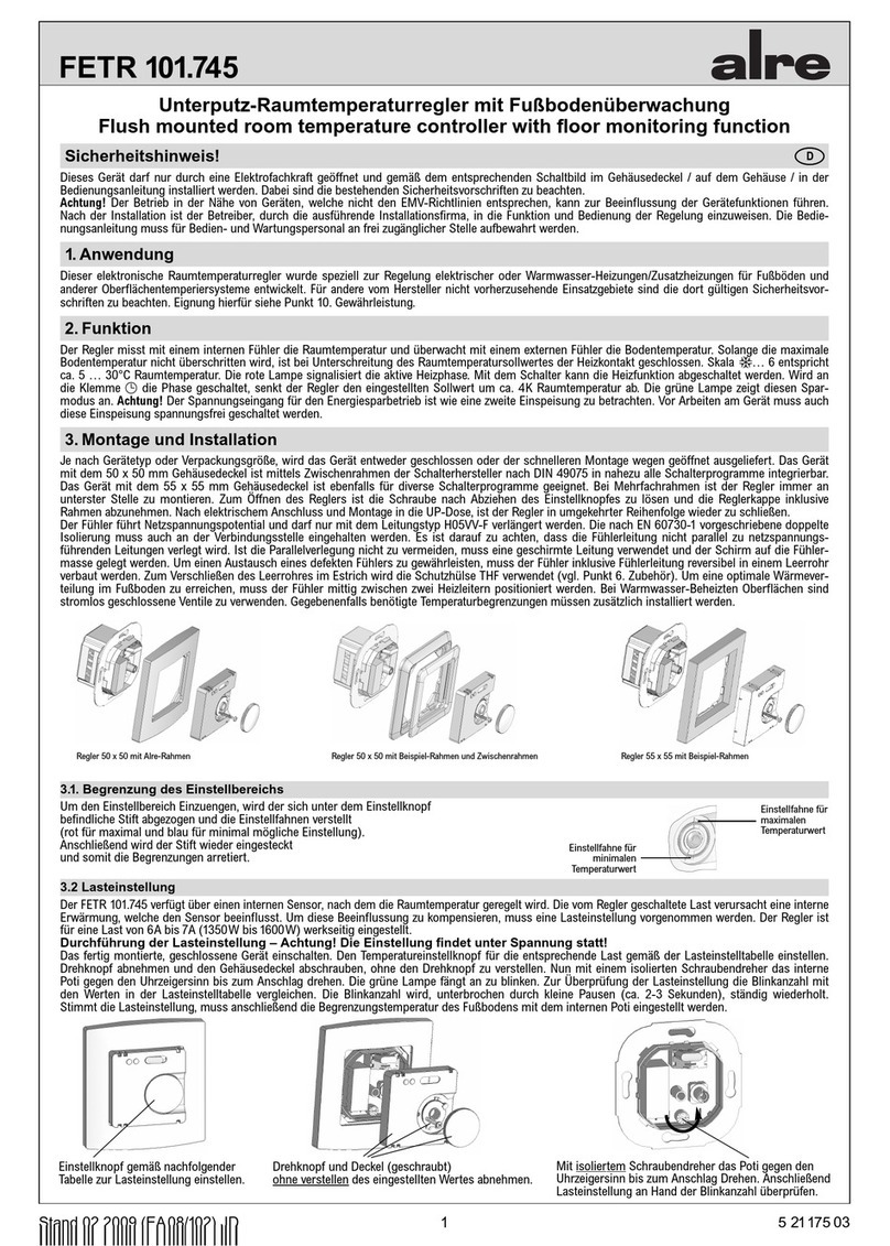
Einbaubedingungen / Mounting Instruction / Instruction de Montage / Instruzione di Montaggio /
Warunki wmontowania
Andruckfeder
Pressure spring
ressort d’appui
Molla di precarico
Sprężyna dociskająca
3
Wskaz wka niebezpieczeństwa
Ten przyrząd może być otwarty tylko przez wykwalifikowanego
elektryka i zgodnie z odpowiednim planem połączeń w
pokrywie obudowy / zostać zainstalowana instrukcja obsługi.
Przy tym należy zwracać uwagę na przepisy bezpieczeństwa.
Zastosowanie
KR …Ten szereg przyrządów zosta specjalnie opracowany
do użycia w technice ogrzewczej w urządzeniach kotłowych
albo magazynowania, stacjach przekazywania ciepła na
odległość i urządzeniach przenoszenia ciepła.
LR …w technice wietrzenia jako nadzór doprowadzonego
powietrza albo jako ogranicznik od elektrycznych grzejników
drabinkowych.
Funkcja przyrządu
Zostanie nastawiona wartość zadana temperatury osiągnięta,
przełącza czujnik kapilary mikro przełącznik i kontakt ogrze-
wacza 1 (czerwony) - 2 (niebieski), otwiera. Kontakt 1 (czer-
wony) - 3 (biały) zamyka. Ogrzewanie zostanie wyłączone.
TB (ogranicznik temperatury)
TW (dozorca temperatury)
TR (regulator temperatury)
STB (ogranicznik bezpieczeństwa temperatury)
Dane techniczne
Zakres temperatur: patrz tabliczka znamionowa
Różica przełączania: patrz tabliczka znamionowa
Prąd przełączania: patrz tabliczka znamionowa,
przy 24V~ min.150 mA
Napięcie łączeniowe: 24 - 230V~, 50 / 60 Hz
Przekrój przyłącza: 1,0 …2,5 mm2
Rodzaj ochrony: IP43 / opcjonaly IP54
max. temperatura nagłówka: 80˚C
max. temperatura czujnika: Ostateczna wartość skali +15%
Stała czasowa: ca. 50 sec. z rurą zanurzeniową
w poruszającej sią wodzie
Zestyki: bezpotencjałowy przełącznik
Rura miedzana i rura kapilarna:
Cu
Tuleja zanurzeniowa: Mosiąc oniklowany albo V4A
Skrętka ochronna: Oniklowana stal
Warunki wmontowania
Przy regulatorach z zewnętrznymi ustawieniami musi najpierw
temperaturowa-gałka do nastawiania, zostać ściągnięta,
zanim do instalacji część górna zostanie odśrubowania.
Cyrkulacja mediów około rury ochronnej, jest dla dokładności
przełączania o największej ważności. Rura ochronna, musi na
całej długości mediów, zostać opłókiwana.
W rurze ochronnej znajduje się sprężyna dociskająca, która
ten czujnik dociska do ściany wewnętrznej rury ochronnej. Tylko
tą sprężyną może zostać zagwarantowany szybki czas zad-
ziałania regulatora. Proszę czujnik, bezpoćrednio przy pomocy
ręki wcisnąć do rury ochronnej, aby rura włoskowata nie
została zgniecona. Umocowanie główki regulatora następuje,
z tym w skrzynce obudowy znajdujących się śrubach, przy
zakleszczeniu na rurze ochronnej.
Regulator przewietrzania LR …posiada kołnierz, z skrętką
ochronną, do bezpoćredniego umocowania w kanale powie-
trznym. Regulator, sam może póżniej zostać zamontowany.
PL

Maßbilder / Dimensioned Drawings / Schéma de connexion / Schema di allacciamento /
Rysunek wymiarowy
Anschluss-Schaltbilder / Wiring Diagrams / Schéma de connexion / Schema di allacciamento /
Przyłącze-plan połączeń
Klemmschraube
Locking screw
vis de serrage
Vite de arresto
Śruba zaciskowa
2x for IP54
Klemmschraube
Locking screw
vis de serrage
Vite de arresto
Śruba zaciskowa
2x for IP54
Handrücksteller
Manual adjuster
remise à zero manuelle
Azzeratore manuale
Ręczne przestawienie
Klemmschraube
Locking screw
vis de serrage
Vite de arresto
Śruba zaciskowa
2x for IP54
weiß kühlen
white cooling
blanc refroidissement
bianco condizionamento
biało chłodzić
weiß kühlen
white cooling
blanc refroidissement
bianco condizionamento
biało chłodzić
weiß kühlen
white cooling
blanc refroidissement
bianco condizionamento
biało chłodzić
blau heizen
blue heating
bleu chauffage
blu riscaldamento
niebiesko ogrzewać
blau heizen
blue heating
bleu chauffage
blu riscaldamento
niebiesko ogrzewać
blau heizen
blue heating
bleu chauffage
blu riscaldamento
niebiesko ogrzewać
rot, red, rouge, rosso,
czerwony
TR/TW TW STB TR
rot, red, rouge, rosso,
czerwony
rot, red, rouge, rosso,
czerwony
TR/TW
rot, red, rouge, rosso,
czerwony
TB/STB
rot, red, rouge, rosso,
czerwony
TB TR
ALRE-IT Regeltechnik GmbH · Richard-Tauber-Damm 10 · D-12277 Berlin
Die von uns genannten technischen Daten wurden unter Laborbedingungen nach allgemein gültigen Prüfvorschriften, insbesondere DIN-Vorschriften, ermittelt. Nur insoweit werden Eigenschaften zugesichert. Die
Prüfung der Eignung für den vom Auftraggeber vorgesehenen Verwendungszweck bzw. den Einsatz unter Gebrauchsbedingungen obliegt dem Auftraggeber; hierfür übernehmen wir keine Gewährleistung. Änderungen
vorbehalten.
The technical data specified herein have been determined under laboratory conditions and in compliance with generally approved test regulations, in particular DIN standards. Technical characteristics can only be
warranted to this extent. The testing with regard to the qualification and suitability for the client’s intended application or the use under service conditions shall be the client_s own duty. We refuse to grant any warranty
with regard thereto. Subject to change without notice.
Les données techniques indiquées dans cette notice d’instructions ont été déterminées sous conditions laboratoires en conformité avec des prescriptions d’essai généralement approuvées, notamment les normes DIN.
Les caractéristiques techniques ne peuvent être garanties que dans cette mesure. La vérification du dispositif en rapport à sa qualification et appropriation pour l’application prévue ou son utilisation sous conditions de
service incombe au client. Nous n’assumons aucune garantie à cet égard. Sous réserve de modifications techniques.
I dati tecnici indicati in queste avvertenze di montaggio sono stati rilevati in laboratorio in conformità con le norme di controllo correnti, soprattutto con le norme DIN. La caratteristiche tecniche vengono garantire solo
in tale misura. Il controllo del dispositivo in relazione all’idoneità per lo scopo di destinazione previsto dal committente e all’impiego in condizioni di servizio è a carico del cliente. Non assumiamo alcuna garanzia al
riguardo. Salvo modifiche di ordine tecnico.
Od nas wymienione techniczne dane zostały ustalone pod warunkami laboratoryjnymi według og lnie obowiązujących przepis w sprawdzania, szczeg lnie DIN przepis w. Tylko tak dalece zostaną zapewnione
właściwości. Sprawdzenie przydatnoćci, dla od zleceniodawcy przewidzianego celu zastosowania wzgl. zastosowanie pod warunkami użycia obowiązuje zleceniodawcę; na to nie przyjmujemy żadnej gwarancji. Zmiany
zastrzeżone.
4
weiß kühlen
white cooling
blanc refroidissement
bianco condizionamento
biało chłodzić
weiß kühlen
white cooling
blanc refroidissement
bianco condizionamento
biało chłodzić
blau heizen
blue heating
bleu chauffage
blu riscaldamento
niebiesko ogrzewać
blau heizen
blue heating
bleu chauffage
blu riscaldamento
niebiesko ogrzewać
This manual suits for next models
5
Other alre Thermostat manuals

alre
alre RFHSB-060.010 User manual

alre
alre FETR 101.745 User manual

alre
alre RTBSU-401.2 Series User manual

alre
alre RTBSU-401.086 User manual

alre
alre JTF Series User manual

alre
alre RFHSU-010 User manual

alre
alre FETR 101.745 User manual

alre
alre KTRRB-040.112 User manual

alre
alre RTBSU-401.086 00 User manual

alre
alre RKDSB-171.000 User manual
Popular Thermostat manuals by other brands

VDH
VDH ALFA 75-MTT user manual

Silvercrest
Silvercrest Classic Model L Operating instructions and safety advices

Nu-Heat
Nu-Heat NTG5110 Homeowner's guide

Honeywell
Honeywell PROGRAMMABLE THERMOSTAT RTH6350 Quick installation guide

Robertshaw
Robertshaw 9915i Quick start installation manual

Salus
Salus ST620VBC instruction manual