TracRac TracONE User manual

Installation Instructions

SKU#
PACKAGED BY:
DATE:
A
B
5
9
1
00-27000-01
4
4
44
44
4
4
10
10
10
10
DETAIL A
6
6
DETAIL B
3
2
77
7
7
8
8
ITEM NO.
PART NUMBER
00-27000-01/QTY.
1
01-27021-01
2
2
01-27023
4
3
01-27012
4
4
01-27006
8
5
RX-11034-3
4
6
01-27015
1
7
01-27016
1
8
01-27043
1
9
01-27013
2
10
01-27035
4
11
01-27014
DESCRIPTION
P/C, DOUBLE T SLOT CROSSBAR
P/C, DOUBLE/TRIPLE CROSSBAR ENDCAP
P/C, MODULAR SADDLE
P/C MODULAR CLAMP
SHIM, ROUNDED
HARDWARE BAG - CLAMPS
HARDWARE
BAG - UPRIGHT/SADDLE
HARDWARE BAG
- PLASTIC TIEDOWNS
P/C, UPRIGH BASE
LF/RR
ASM, MODULAR UPRIGHT
P/C UPRIGHT BASE RF/LR
2
Fall River Mass.
TITLE:
SCALE:
1:10
TracONE
-
REV:
R
DESIGN:
EBB
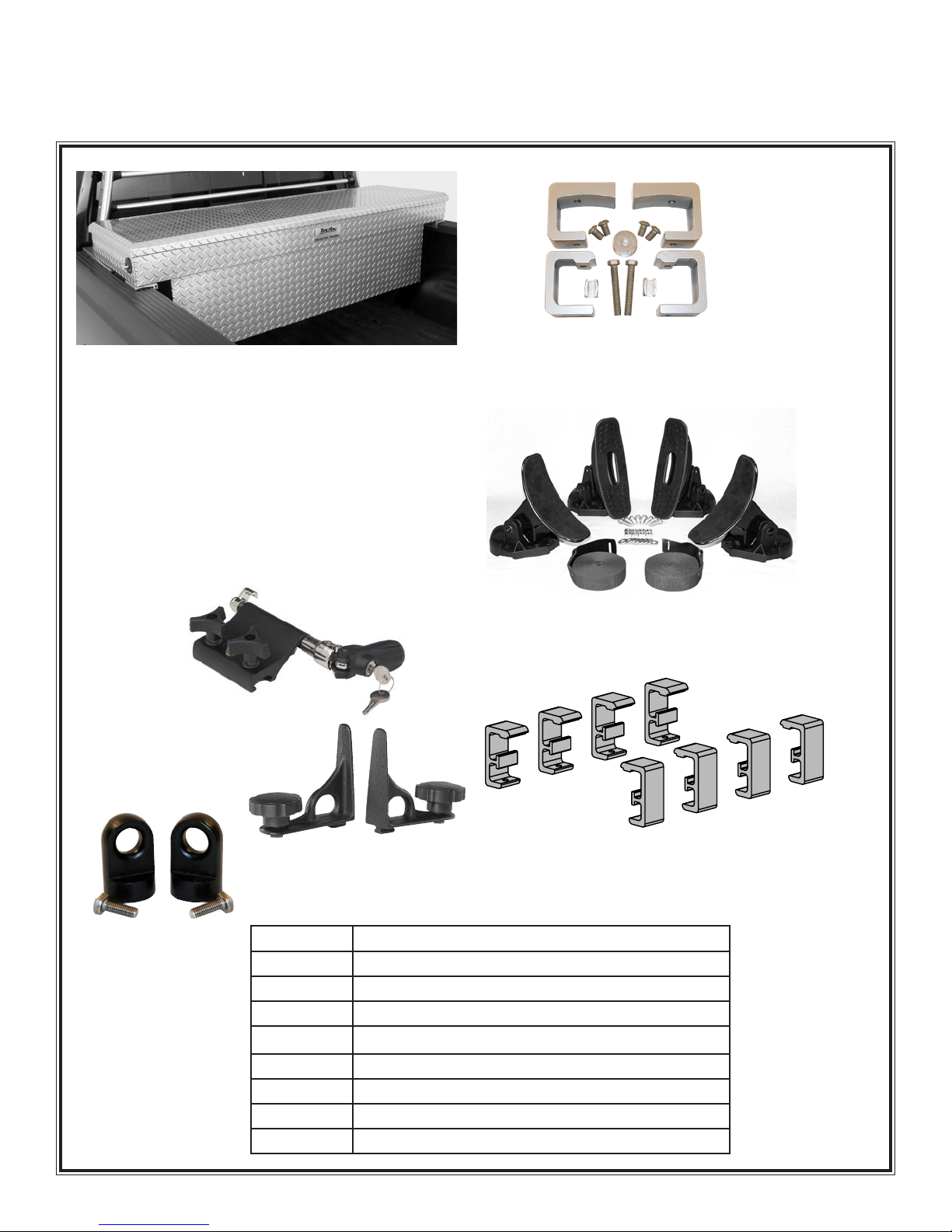
TracONETM Accessories
Part # Description
25250 TracBox - Full Size, Crossover, Powder Coated Toolbox
41000 Toolbox Mount Kit
25110 Aluminum Crossbar Tiedowns (Qty: 2)
44400 Plastic Loop Crossbar Tiedowns ( qty: 4)
44300 Kayak Mount Kit
25411 Bike Mount Kit
34000 Tacoma Mount Kit
41500 Tacoma Mount Kit with Toolbox Mount Kit
TracONE Toolbox Mount Kit - The toolbox mount kit
includes Aluminum Shims & Hardware to mount any
crossover toolbox that will fit your truck.
TracBox - Full size, Silver Powder Coated, Crossover
Toolbox.
Features:
Weatherproof Seals•
Dual Push Button•
Shocks
Heavy Duty Gas•
Shocks
2 Stage Rotary Latch•
Foam Filled Lid•
5 Compartment Sliding•
Tray
L: 70 in. W: 20 in. H 20 in.•
Kayak Rack Kit - Complete with all of the mounting
hardware. The Kayak Kit has felt lined rear saddles and
rubber front saddles for easy loading and a secure fit.
Bike Mount - mount your bikes to the crossbar safely and
securely.
Aluminium Die-Case
CrossBar Tiedowns
Qty: 2 Tiedowns
Plastic Loop Tiedowns
Qty: 2 Tiedowns
Toyota Tacoma Mount Kit- These replacement clamps
work with your existing hardware to mount your TracONE into
the Tacoma Deck Rail System.
Tiedown Options-

These instructions will guide you through the 3 main component assemblies:
Upright units1.
Cross bars2.
Clamp units3.
Please reference the drawing below for a general overview.
Tool you will need:
3/16” Allen Key•
7/32” Allen Key•
Tape Measure•
9/16” Socket and Socket Wrench•
Recommended:•
Torque Wrench
7/32” Allen Drive Bit
Non-Impact Drill
Installation Instructions
A
B
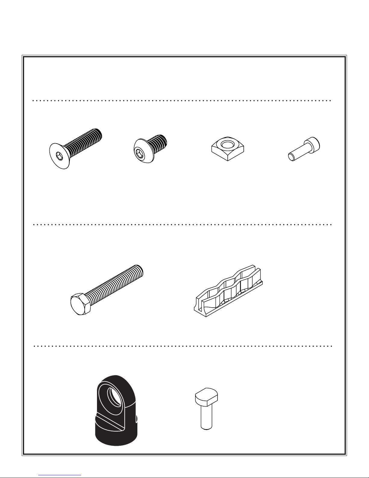
Hardware Bag Contents
01-27016 Hardware Bag-1
Upright/Saddle Hardware
01-27015 Hardware Bag-2
Clamp Hardware
01-27043 Hardware Bag-3
Plastic Tie-down Hardware
Item # 12
3/8 - 16 x 1.5”
Flat Head Cap Screw
Qty - 16
Item # 13
3/8 - 16 x .625”
Button Head Cap
Screw
Qty - 8
Item # 14
3/8 - 16
Square Nut
Qty - 8
Item # 15
M6-1
Socket Head Cap
Screw
Qty - 4
Item # 18
3/8 - 16 x 2.5”
Hex Head Cap Screw
Qty - 8
Item # 19
3.0”
U - Channel
Qty - 8
Item # 20
Plastic Tiedown
Qty - 4
Item # 21
3/8 - 16 x 1.125”
T-Bolt
Qty - 4
Hardware
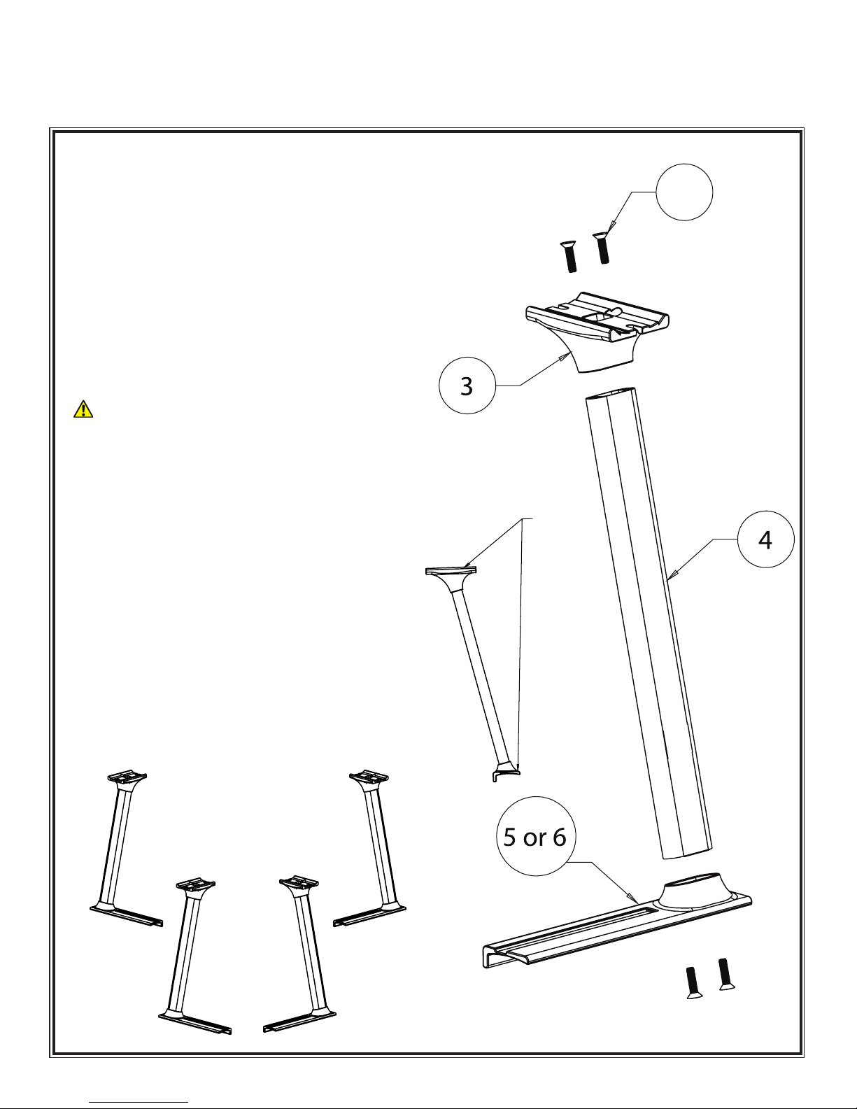
1.1 Upright Assembly
First take the upright (Item 4) and insert it into a1.
modular saddle (Item 3).
Bolt the saddle through the top by using two 3/8”-162.
flat head cap screws (Item 12) and tighten using
an 7/32” Allen Wrench (or 7/32” Allen Drive Bit).
Torque the 3/8” -16 FHCS to 32 ft-lbs. We recom-
mend threading both flat head cap screw initially by
hand to ensure that you don’t cross thread the bolt.
1.1.1 When tightening the 3/8” flat head cap screws
ensure that the allen key is fully seated in the bolt so
that it will not strip
Now take the upright and saddle and bolt it to the
3.
modular base (Item 5)
Bolt the base through the bottom by using two4.
3/8”-16 flat head cap screws (Item 12) and tighten
usingan 7/32” Allen Wrench (or 7/32” Allen Drive
Bit.) Torque the 3/8” -16 FHCS to 32 ft-lbs.
For the other front upright repeat steps one through
5.
four, except use (Item 6) in step three.
Repeat Steps 1-5 on each of the uprights6.
1.1.2 NOTE: Item 5 and Item 6 are mirror images of each
other. Reference the packing checklist to confirm what
part to use.
Step 1
Part 1 - Uprights
12
Figure 1.1
Note:
Both
surfaces
must be
parallel
with each
other
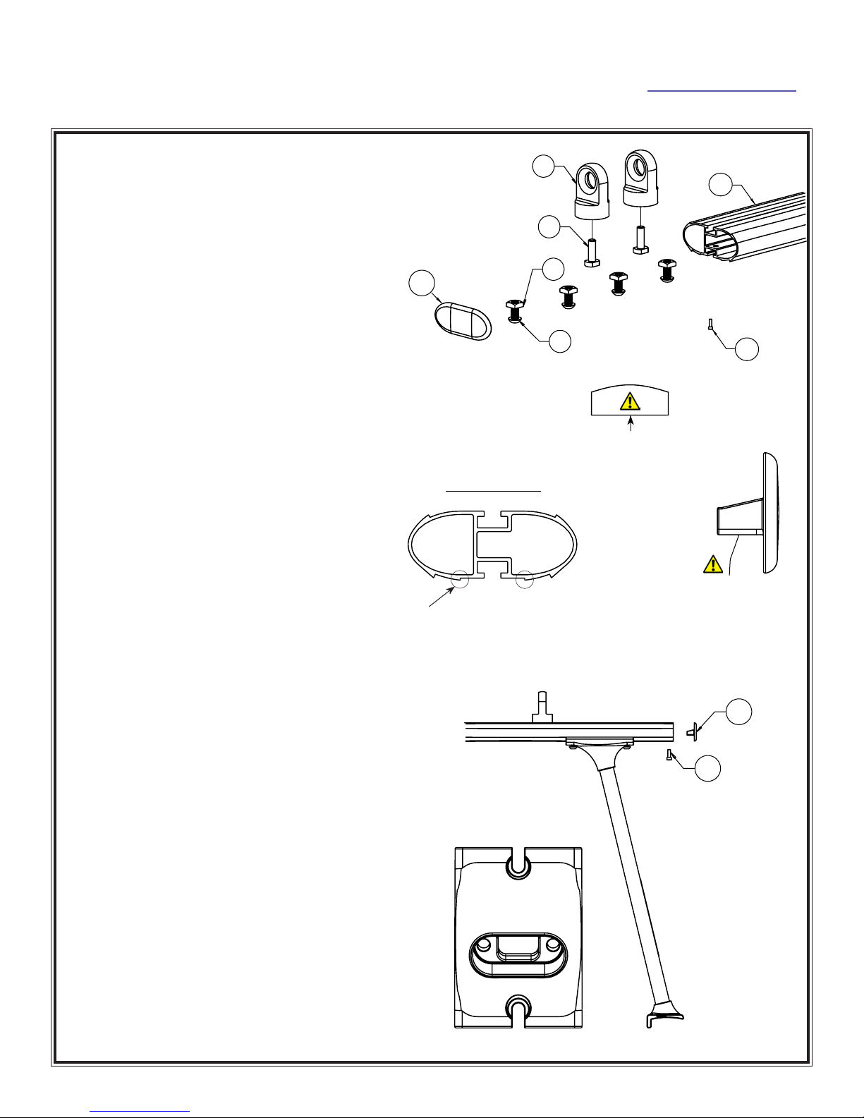
Part 2 - Cross Bars
Step 2
Step 3
Figure 3.1
2.1 Crossbar Assembly
Take the double T-Slot crossbar (Item 1) and
1.
insert four square nuts (Item 14) into the bot-
tom T-Slot. Reference Figure 2.1, 2.2 & 2.3
Insert a T-bolt (Item 21) through the bottom of
2.
the cross bar tie-down (Item 20) and slide the
unit into the top track of the crossbar so that
both the bolt and the tiedown are locked into
the t-track.
Insert the Crossbar End Cap with the flat3.
mounting surface facing down into the end
of the crossbar. Using the clearance hole on
the bottom of the crossbar and the M6 SHCS
(Item 15). Tighten down the M6 SHCS using a
3/16” Allen Key. Repeat on the opposite side.
Reference Figure 3.1
Repeat steps 1-3 for the remaining crossbar.4.
3.1 Front & Rear Crossbar Installation
Now place the assembled crossbar on top1.
of the assembled uprights. Make sure the
crossbar is right side up. Reference Figure 2.3
Slide the Square Nuts (Item 14) so that they
2.
are directly above the slotted hole in the
saddle. Insert the 3/8 BHCS (Item 13) into
the Square Nuts (Item 14) and tighten the
cap screws, using an 7/32” Allen Wrench (or
7/32” Allen Drive Bit) Do not fully torque the
screws until Step 8 of the Truck Installation
3.1.1 Note: Make sure that the BHCS sits completely
within the recessed area of the saddle casting. See
Figure 3.2
Repeat Steps 1 and 2 for the opposite upright.3.
Repeat Steps 1-3 for the remaining crossbar.4.
2.4.1 t h i s f a c e d o w n
2.2.1 no t e : f l at
f a c e o f t h es q u a r e
n u t m u s t f a c e t h e
o p e n s l o t o f t h e
c h a n n e l
Figure 2.2
Crossbar End View
Top
Bottom
2.3.1 g r o v e f i t s i n t o s a d d l e
Figure 2.3 Figure 2.4
13
14
21
20
2
15
2
15
Figure 3.2
Figure 2.1 1

Part 3 - Clamps & Truck Installation
4.1 Base Clamp Assembly
Take a modular clamp (Item 7) and thread a 3/8”-161.
hex head cap screw (Item 18) through the bottom
as shown. (See note about Loc-Tite)
Now take a C channel clamp foot (Item 19) and2.
place it on top of the 3/8” hex head cap screw as
shown.
Repeat steps one and two for the remaining seven3.
clamps.
Step 4
Step 5
4.1.1 Note: Clamp feet must be used to ensure proper clamping
force distribution between the rack and the truck bed and
prevent damage
5.1 Front Upright and Base Clamp Assembly
Now take the rounded shims (Item 8) and place1.
them on the sidewalls of you truck approximately
where the uprights will sit.
The front uprights will be directly behind the rear win-
dow. Place the unit as far forward as possible
Place the front uprights on top of the rounded2.
shims (Item 8) making sure that the rubber shims
are completely under the bases.
With one pair of uprights now on the truck, they3.
must be secured using two Modular Clamps (Step
4). When positioning the clamps make sure they
are spaced as far apart as possible.
First torque the clamps on either side of the rack4.
towards the cab, then follow with the other two
clamps towards the rear of the truck
Torque down the HHCS to 14 lb-ft using a 9/16”5.
socket and a torque wrench.
5.2 Rear Upright and Base Clamp Assembly
The rear uprights should sit as far towards the tailgate
as possible without the base hanging off the back of
the bed rail, while maximizing the distance between the
clamps (Figure 5.2)
Place the rear uprights on top of the rounded shims
6.
(Item 8) making sure that the rubber shims are
completely under the bases.
With the second pair of uprights now on the truck7.
they must be secured using two of the previously
assembled (Step 4) clamps (2 per upright). When
positioning the clamps make sure they are spaced
at least 7 5/16 inches apart. Any less of a distance
will reduce the load capacity of the rack. You may
adjust the position of the rack on the bed to ensure
that this distance can be achieved
Repeat Steps 3-5 on the rear rack.8.
Finally with the uprights secured you now want to9.
take a measuring tape and center your crossbars.
Once centered use your 7/32” Allen Wrench (or
7/32” Allen Drive Bit) to fully secure your crossbars.
Torque the BHCS to 27 ft-lbs.
5.1.1 no t e : Bes u r e t o k e e p t h er u B B e r
s h i m u n d e r t h eB a s ew h e n t i g h t e n i n g t h e
c l a m p s
5.1.2 maximize distance
Figure 5.1
5.2.1 When tightening the 3/8” flat head cap
screws ensure that the allen key is fully
seated in the bolt so that it will not strip
75/16 In.
4.1.2 We recommend
that you apply Loc-Tite
(red) to any thread that is
engaged with the clamp.
4.1.3 HHCS (Item 18)
should be re-torqued every
5000 miles.
Figure 5.2
19
18
7
Apply Loc-Tite
within this area
Table of contents
Other TracRac Automobile Accessories manuals


