Tractel ET User manual

M6062M –04/2007
POULIES OUVRANTES POUR CABLES
WIRE ROPE SNATCH BLOCKS
ET -EH - EC
TRACTEL SOLUTIONS S.A.S.
77-79rueJules Guesde -F-69564 Saint-Genis-Laval
Tel: +33 (0)4 78 50 18 18 –Fax: +33 (0)4 72 66 25 41
www.tractelsolutions.com- info@tractelsolutions.com
SIRET350 732939 000 37 –RCS Lyon B350 732 939
F
GB
NOTICE D’UTIL ISATIO N
INSTRUCTIONS FOR USE
EH
ET
EC

M6062M –04/2007
SOMMAIRE
CONSIGNES PRIORITAIRES ...................................................................................page 1
PRESENTATION ET DESCRIPTION DE L’APPAREIL .......................................page 2
MODE OPERATOIRE...........................................................................................pages 2-6
VERIFICATIONS REGLEMENTAIRES OBLIGATOIRES....................................page 7
STOCKAGE ET ENTRETIEN DUMATERIEL........................................................page 7
CONTENTS
PRIORITYINSTRUCTIONS.......................................................................................page 8
PRESENTATION AND DESCRIPTIONOF THE EQUIPMENT ..........................page 9
OPERATING INSTRUCTIONS..........................................................................pages 9-13
COMPULSARY INSPECTIONS AND CHECKS..................................................page 14
STORAGE AND MAINTENANCE..........................................................................page 14
F
GB

M6062M –04/2007
Afin d’ass ure r l’amé l io ra ti on co ns ta n te de s es produits , TRACTEL SOLUTION S S AS s e
réserve le droit d’apporter toute modification jugée utile aux matériels décrits dans la
présente notice.
Cette notice contient toutes les prescriptions nécessaires à une utilisation optimale et sûre
des poulies ouvrantes CHARLET.
CONSIGNES PRIORITAIRES
Avant utilisation et maintenance des poulies ouvrantes Charlet, il est indispensable pour la
sécurité d’emploi du matériel et son efficacité, de faire prendre connaissance et de se
conformer aux présentes instructions par des opérateurs formés en conséquence.
Cette notice doitêtre conservée à disposition de toutopérateur.Des exemplaires
supplémentaires peuvent être fournis sur demande.
Les fiches techniques N° 6054 –6061 –6055 , sont disponibles pour ces produits.
Contacter Tractel Solutions pour toute information complémentaire.
NE JAMAIS UTILISER POUR LE LEVAGE DE PERSONNE.
Les poulies Charlet permettent d’effectuer des opérations nécessitant de garantir une
grande sécurité. En conséquence, assurez-vous que la personne à qui vous en confiez
l’utilisation est apte à assumer les exigences de sécurité que comportent ces opérations.
Ne jamais dépasser la charge maximale d’utilisation (CMU/ WLL). Chocs ou conditions
particulières d’utilisation doivent être pris en compte lors du choix du produit adapté.
TRACTEL SOLUTIONS SAS décline toute responsabilité pour les conséquences d’un
démontage ou d’une modification apportée hors de son contrôle. Spécialement en cas de
remplacement de pièces d’origine par des pièces d’une autre provenance.
Soudage ou modifications sur ce produit doivent obligatoirement faire l’objet d’un accord
préalable de la partde Tractel Solutions.
Pour des utilisations de levage de charge (charge motrice), l’utilisateur doit se conformer
à la réglementation de sécurité applicable à ce domaine d’emploi.
N’utiliser une poulie Charlet qu’avec un câble compatible –cf. tableaux (C).
Appliquer, et faire appliquer, les consignes interdisant à toute personne de stationner ou
circuler dans le périmètre de chute éventuelle de la charge.
Avant montage, vérifier que la résistance du point d’arrimage correspond aux conditions
d’emploi indiquées sur le tableau (A) ci-après.
Lors de la dépose, veiller à ce que la position verticale de la poulie soit stable, sans
risque de basculement. En cas d’instab ilité dans la zone de dépose, coucher la poulie sur
son flanc.
Toujours utiliser, pour les manutentions, les équipements de protection individuels
préconisés (gants, chaussures de sécurité, casque,lunettes,etc).
Ne jamais passer, stationner ou laisser une partie de votre corps, sous une charge
suspendue. Ne jamais laisser sans surveillance une charge suspendue.
Ne jamais déplacer une charge suspendue au-dessus ou à proximité de personnes.
Avertir les personnes présentes alentour lorsque s’opère le levage ou le déplacement de
la charge.
Ne jamais utiliserune poulie endommagée ou lorsque vous avez des doutes sur son bon
fonctionnement. Contrôler régulièrement le bon état du matériel (voir ci-dessous).
Ne jamais utiliser les poulies en atmosphère agressive.
Seules les pièces de rechange d’origine TRACTEL SOLUTIONS SAS peuvent être
utilisées.
F
1
M6062M –04/2007
PRESENTATION ET DESCRIPTION DE L’APPAREIL
Présentation du matériel
Les poulies de renvoi ET, EH et EC sont destinées à des installations temporaires de levage ou
de traction à câble.
Les poulies ouvrantes permettent un montage/ démontage ou des modifications de configuration
rapides.
MODEOPERATOIRE
Informations générales
- Utilisation avec des gants de manutention.
- Avant montage, vérifier que la capacité maximale d’utilisation de la poulie et la résistance du
point d’arrimage correspondent aux conditions d’emploi (voir tableau A).
- Utiliser un câble de taille adaptée -lechoix du câbleestunegarantiepour lasécuritéet le
fonctionnementdelapoulie(voir tableaux C–selon modèle).
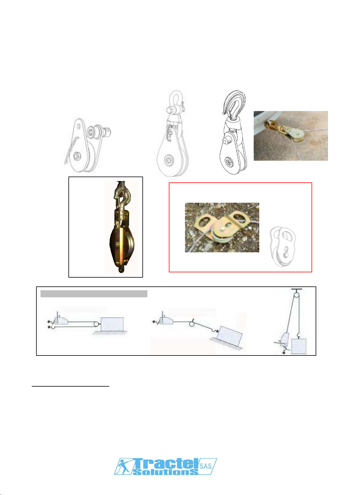
Poulie EH
Poulie ETM
ET avec manille
Poulie ETC
ET avec crochet
Poulie ETA
ET avec axe
Poulie ciseaux EC
2
Mouf lage en traction
Déviationdecâble
Mo
uflage en levage
Quelques exemples d’installations

M6062M –04/2007
Treuil
α
Charge
Charge au
ringot
Charge à la
suspente F
Treuil
α
Ch
arge
Charge à la
suspente
Détermination de la charge maximale utile des poulies
La charge maximale d’utilisation (CMU) gravée ou plaquée sur les poulies correspond à la charge
maximale autorisée à la suspente. Cette charge F est fonction de la CMU du treuil utilisé et de l’angle
formé par le câble entrant et sortant de la poulie. Le tableau (A) ci-dessous permet de vérifier en
fonction des conditions d’implantation du treuil et des poulies de renvoi que F est bien inférieur à la
CMUde la poulie.
Toujo urs v é rif ie r que :
F < CMU poulie
F < résistance du point d’amarrage.
IMPORTANT : dans le cas de l’utilisation d’une poulie EH pour un
mouflage 3 brins, ajouter à la charge à la suspente F décrite ci-
dessus la charge au ringot. La valeur totale de la charge ainsi
déterminée doit toujours rester inférieure à la Charge Maximale
d’Utilisation (CMU) de la poulie et à la résistance du point
d’amarrage.
Réduction de la résistance du câble
Le rapport =
du diamètre du réa au diamètre du câble, ou rapport
d’enroulement, affecte la résistance à la traction du câble
suivant les valeurs indicatives du tableau (B) ci-contre :
* Lesvaleursci-dessus, donnéesà titre indicatif, varient suivantla construction du câble.
Pourplusde précisions, consulterle fournisseur du câble.
Angle
α
Charge à lasuspente
F
0° CMUtreuil x 2
15° CMUtreuil x 1,98
30° CMUtreuil x 1,95
45° CMUtreuil x 1,85
60° CMUtreuil x 1,73
90° CMUtreuil x 1,41
120° CMUtreuil x 1
150° CMUtreuil x 0,52
180° CMUtreuil x 0
Tableau (A)
Tableau (B)
Rapport
d’enroulement
Réduction*
6 21%
8 17%
10 14%
15 11%
20 9%
Ø primitif (= Ø fdg + Ø câble)
Ø câble
Exemple pour EH
si α= 0°
F = 2xCMU treuil + charge au ringot
3

M6062M –04/2007
Poulies EC
- Pour monter/ démonter le câble: faire pivoter les flasques
de la poulie ciseaux, positionner/ retirer le câble sur le réa et
refermer.
- Ins tal ler l a pou lie par l’ inter média ir e d ’un ac c es s oir e
(manille, axe, élingue, cochet,…) repris sur l’anneau des 2
flasques
- L’arrimage doit e mprisonner les deux flasques, afin de
rendre impossible l’ouverture sans dépose de la poulie.
Ø câble Ø ext.
réa
CMU* min max E H KABpoids
t mm mm mm mm mm mm mm kg
référence
1.6 8 9 100 180 60 66 40 2.2 EC1.6-100E9
3.2 10 12 160 260 80 86 50 4.8 EC3.2-160E12
5 13 15 200 330 100 106 60 9.3 EC5-200E15
8 16 18 250 410 120 138 80 19.4 EC8-250E18
* Charge Maximale d’Utilisation
flasques
anneaux
H
B
A
K
4
Tableau (C1)

M6062M –04/2007
Poulies ET
- Pour monter/ démonter le câble : retirer la goupille (1), dévisser
l’axe (2), faire pivoter le flasque (3) et positionner/ retirer le câble
sur le réa (4).
- Refermer la poulie en reproduisant les étapes ci-dessus et sans
oublier de verrouiller la poulie avec la goupille de sécurité (1).
Ø réa Ø câble
hauteur poids références
F E C I
CMU
(1) Ø
FdG
(2)
Ø
EXT
Ø
Min/Max
crochet
manille
axe
ODCroc/
manille
axe
t mm mm mm mm mm mm
mm
mm
kg kg
palier
crochet manille axe
2 60 79 9/10 218 219 92 30 33 2.7 1.6 Bba(3)
ETC2-79E10 ETM2-79E10 ETA2-79E10
5 90 114 12/14 318 327 142
39 51 8 4.5 Bb(4) ETC5-114E14 ETM5-114E14 ETA5-114E14
5 140 165 12/14 369 378 167
39 51 10.5 7 Bb ETC5-165E14 ETM5-165E14 ETA5-165E14
8 112 142 17/19 397 400 182
48 58 15 8.5 Bb ETC8-142E19 ETM8-142E19 ETA8-142E19
8 177 209 17/19 431 434 216
48 58 20 13.5
Bb ETC8-209E19 ETM8-209E19 ETA8-209E19
8 221 262 17/19 457 460 245
48 58 25 18 Ro(5) ETC8-262E19 ETM8-262E19 ETA8-262E19
8 275 326 20/23 495 498 283
48 58 29 23 Ro ETC8-326E23 ETM8-326E23 ETA8-326E23
12.5 112 145 20/23 453 444 201
57 68 30 24 Bb ETC12-145E23
ETM12-145E23
ETA12-145E23
12.5 174 216 20/23 488 479 236
57 68 35 28 Ro ETC12-216E23
ETM12-216E23
ETA12-216E23
12.5 174 216 26/29 497 488 245
57 68 35 28 Bb ETC12-216E29
ETM12-216E29
ETA12-216E29
15 221 262 20/23 560 574 270
57 83 38 30 Ro ETC15-262E23
ETM15-262E23
ETA15-262E23
15 275 326 20/23 592 607 302
57 83 45 36 Ro ETC15-326E23
ETM15-326E23
ETA15-326E23
15 355 420 20/23 639 653 349
57 83 65 52 Ro ETC15-420E23
ETM15-420E23
ETA15-420E23
20 174 216 26/29 553 576 260
44 89 39 31 Ro ETC20-216E29
ETM20-216E29
ETA20-216E29
20 224 268 35/38 583 606 260
44 89 56 45 Ro ETC20-268E38
ETM20-268E38
ETA20-268E38
20 349 410 35/38 653 676 360
44 89 70 56 Ro ETC20-410E38
ETM20-410E38
ETA20-410E38
25 221 262 26/29 648 665 296
52 98 62 48 Ro ETC25-262E29
ETM25-262E29
ETA25-262E29
25 270 326 26/29 680 697 628
52 98 85 63 Ro ETC25-326E29
ETM25-326E29
ETA25-326E29
32 270 334 42/46 713 761 359
59 110
95 70 Ro ETC32-334E46
ETM32-334E46
ETA32-334E46
32 443 518 42/46 805 853 451
59 110
135 100 Ro ETC32-518E46
ETM32-518E46
ETA32-518E46
(1) Charge Maximale d’Utilisation (2) Fond de Gorge (3) bague bronze autolubrifiée (4) bague bronze (5) roulement
2
4
1
3
5
Tableau (C2)

M6062M –04/2007
F
E
B
D
G
H
C
A
I
J
O
M
N
K
L
P
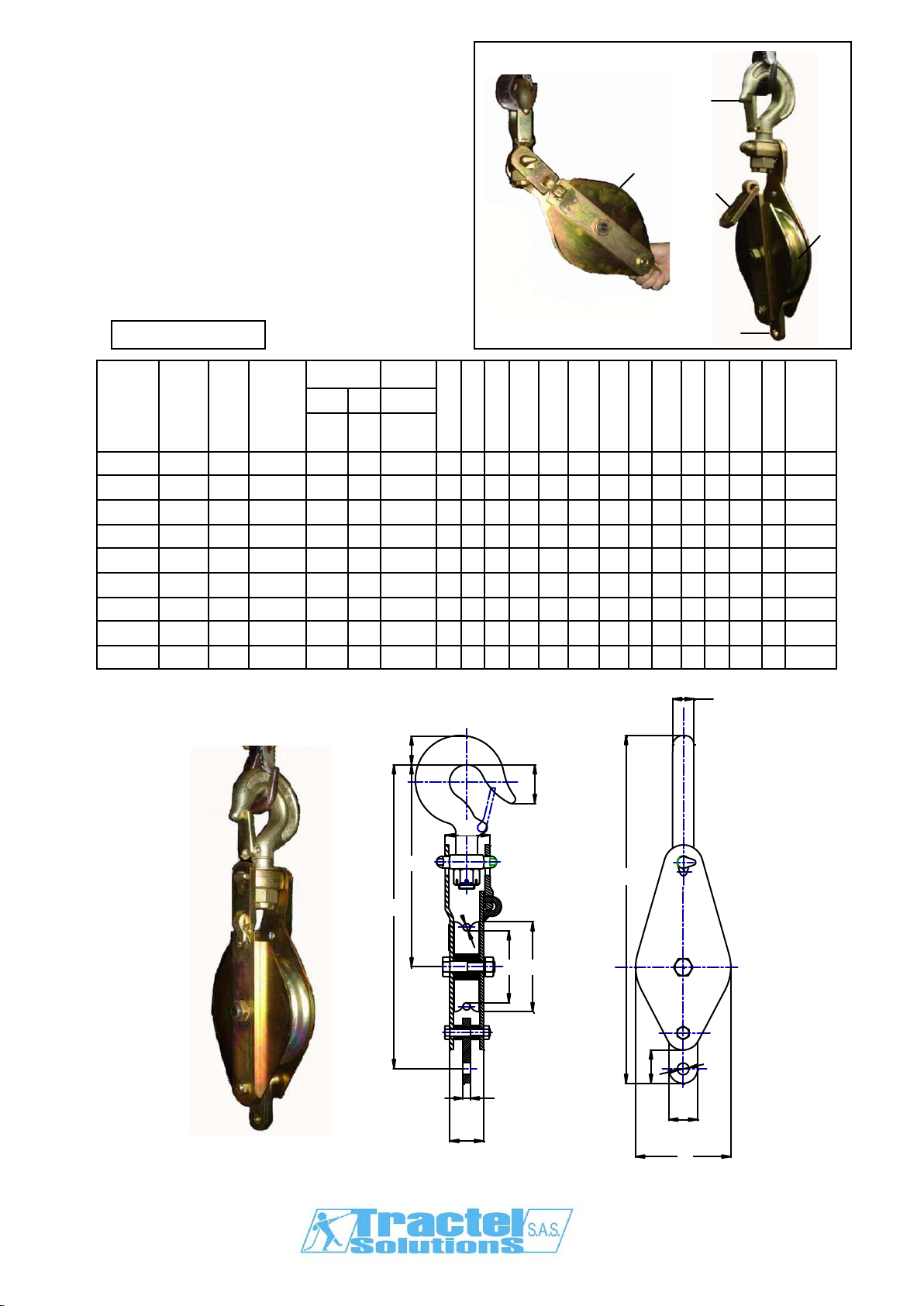
Poulies EH
- Pour mont er/ démonter le câble : faire pivoter
le corps de la pou lie (1) jusqu’à l’ouverture du
flasque ouvrant (3) puis positionner/ retirer le
câble sur le réa et refermer.
- Refermer la poulie en reproduisant les étapes
ci-dessus et sans oublier de verrouiller
convenablement le flasque ouvrant (2).
- Le câble peut être mis en tension.
Ø réa Ø câble
F E C
Réf. Code
groupe
CMU*
(t) Palier
Ø
FdG**
Ø
Ext
Ø
min/max
A B
D G H I J K L M
N O P Poids
(kg)
E303H 80869 1 Bb & Gr
80 100
8/ 9 33
43
24
225
386
355
106
38
50 37
32
13 8 3
E460H***
80969 1,6 Bb & Gr
132 160
7,5/ 8,3 41
59
30
315
541
482
170
58
77 56
40
17.5
16
7
E313H 80889 2 Bb & Gr
132 160
10/ 12 41
59
30
315
541
482
170
58
77 56
40
17.5
16
7
E323H 80909 3,2 Bb & Gr
160 200
13/ 15 49
60
38
369
631
562
210
80
94 53
40
17.5
16
15,5
E470H***
80989 3,2 Bb & Gr
160 200
10/ 11,5
49
60
38
369
631
562
210
80
94 53
40
17.5
16
15,5
E490H 81029 5 Bb & Gr
160 200
13/ 15 49
60
38
368
646
567
210
80
94 69
60
25 20
17
E333H 80929 5 Bb & Gr
210 250
16/ 18 49
60
38
405
719
640
260
88
94 62
60
25 20
20,2
E480H***
81009 6,4 Ro 275 336
14/ 16,3
68
80
48
510
896
794
343
92
110
75
70
30 25
34
E347H 80949 8 Ro 275 336
21/ 23 68
80
48
510
896
794
343
92
110
75
70
30 25
34
* Charge Maximale d’Utilisation ** Fond de Gorge *** pour câbles tirfor® Dimensions en mm
Bb & Gr : bague bronze & graisseur axial
Ro: roulements à billes
1
2
3
ringot
suspente
6
Tableau (C3)

M6062M –04/2007
VERIFICATION REGLEMENTAIRES OBLIGATOIRES
Faire effectuer contrôles et opérations de maintenance par des personnes compétentes et formées
Vérification lors de la mise (ou remise) en service: obligations réglementaires de l’utilisateur
suivant arrêté du 1er mars 2004etart. R233du Codedu Travailfrançais.
Vérification périodique suivant arrêté du 01/03/2004 préconisée tous les 12 mois.
Un examen approfondi portant en particulier sur toute altération des pièces par choc, corrosion,
fissuration, déformation, doit être effectué au moins 2 fois par an et chaque mois en utilisation
intensive ou en milieu agressif.
Tractel Solutions SAS reste à disposition pour réaliser toute vérification de ce produit.
Avant chaque utilisation
Vérifiezvisuellement toutes les parties de lapoulie.
Vérifier la présence et l’état des linguets et goupilles de sécurité.
Vérifier l’absence de jeu sur l’axe du réa et sa libre rotation sans voile.
Ex ame n appr ofondi
Les poulies utilisées dans un établissement visé à l’article L.231-1 du code du travail, doivent,
conformément à l’article R. 233-11 dudit code, être soumis tous les douze mois à une vérification
périodique comportant un examen ayant pour objet de déceler toute détérioration, ou autre limite
d’emploi, susceptible d’être à l’origine de situations dangereuses.
Vérifiez si la poulie ne présente pas de déformations, fissures ou autres défauts. Si la suspente
présente une usure supérieure à 10%, la poulie doit être remplacée.
Vérifier l’aspect de la gorge du réa et l’absence de choc et d’usure.
Vérifier l’absence de fissures sur le manchon soudé et de déformation sur l’axe de verrouillage.
Vérifier les suspentes :
o Présence et bon f onctionne ment du linguet,
o Absence de déformation des flasques, du crochet, de la manille ou de l’axe,
o Présence des goupilles de blocage et des chaînettes.
Vérifiez la présence et la lisibilité du gravage ou de la plaque signalétique.
Reportez les éléments de contrôle dans un registre.
STOCKAGE ET ENTRETIEN DU MATERIEL
Stockage
Il est recommandé de retirer le câble avant de stocker la poulie. Conserver la notice d’utilisation avec
la poulie. Le lieu de stockage do it être sec et à l’abr i des inte mp éries.
S’assurer qu’aucune charge n’est appliquée à la pou lie pendant le stockage.
Anomalies de fonctionnement
La rotation du réa doit être libre et sans voile.
La poulie doit s’ouvrir et se refermer librement.
En t r e t ie n d e l ’app are il
Faire effectuer les contrôles de maintenance par des personnes compétentes et formées
Po ur le s mod èl e s équ ip é s d’u n gr a is s eu r , la f r éq ue n c e de gr a is s ag e e s t v a r ia ble s uiv a nt
l’app lication, mais ne saurait être inférieure à 30 jours, avec une graisse adaptée à l’application.
Pour les modèles équ ipés en pa liers auto-lubrif iés, vérif ier régulièrement l’état de ceux-ci.
Toute pièce présentant un défaut doit être remplacée par une pièce d’origine Tractel Solutions
SAS.
Tout matériel déformé doit être immédiatement retiré du service.
7

M6062M –04/2007
Always concerned to improve the quality of its products, TRACTEL SOLUTIONS S.A.S
reserves the right to modifythe specifications of the equipment described in this manual.
This manual outlines all necessary instructions for the safe and the correct operation of
Charletsnatch blocks.
PRIORITY INSTRUCTIONS
Before using andmaintaining this Charlet snatchblock, for maximum safety and efficiency,
makesure these instructions are read, understood and appliedby trained users.
This manual shouldbe made available to every operator. Extra copies of thismanual willbe
supplied on request.
Technical data sheets #6054, 6061 –6055 are also available.
Contact Tractel Solutions for any additional information.
NEVER USE FOR PERSONNELLIFTING
Never use this snatch block for a load exceeding its Working Load Limit (WLL). Shock
loading or specific conditions must also be taken into account when determining the
appropriate product.
Charletsnatch blocks allowoperations with a high safety level.Make sure thatthe people
in charge meetthe safety requirements of these operations.
TRACTEL SOLUTIONS SAS disclaims all responsibility for the consequences due to
disassembly or modification of the product without prior agreement, especially in case of
original components replacementby spare parts ofother origin.
Modification or welding on this product is strictly forbidden without prior agreement from
Tractel Solutions.
For lifting applications, make sure the local applicable regulation is applied before using
this product.
Only use wire rope that corresponds to the snatch block characteristics.
Itis strictlyforbidden to either stand orwalk underthe load.
Nevermove the hanging load above or near people.
Attach the block to a fixed anchoring point and ensure that it can support the snatchblock
WLL
Warn the people around during the lifting ormoving of the load.
Neveruse a damaged pulley or ifyou have a doubtover its correct functioning.
Neveruse the pulleys in aggressive atmospheres.
When the snatch block is standing vertically on the floor, make sure it cannot tip. If the
work area is not stable, then lay the snatch block on its lateral side plate.
Always use the adapted individual protection equipment (gloves, safety boots, helmet,
glasses…) during the material handlings.
Regularly examine the condition ofthematerial (seebelow).
Only TRACTEL SOLUTIONS SAS genuine spare parts should be used.
GB
8

M6062M –04/2007
PRESENTATION AND DESCRIPTION OF THE EQUIPMENT
Presentation of the equipment
ET, EH and EC return pulleys are suitable for temporary lifting or pulling applications.
Snatch blocks permit a quick installation and removing, or quick fitting modifications
OPERATING INSTRUCTIONS
General informations
- Use safety gloves and usual PP equipments w hen operating
- Attach the block to afixed anchoring and ensure the snatch block WLL and resistance of the
anchoring point correspond to conditions of us -refer table (A).
- Use a suitable w ire rope -Wire ropechoice is theguarantee of security and goodfunctioning
of the snatch block –refer table (C) depending on model.
EH
pulley
ETMpulley
ET w ith shackle
ETC pulley
ET w ith hook
ETA pulley
ET w ith axle
EC sw ing
pulley
Traction block assembly
Change of wire rope direction
Installation examples
Lifting block
assembly
9
M6062M –04/2007
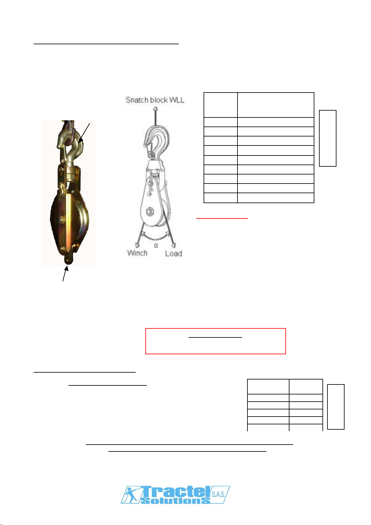
Calculation of loading of a snatch blocks
The maximum Wor king Load Limit (WLL) w ritten on the side of the block is the maximum load that
should be exerted on the block and its connecting fitting.
This total load value F varies w ith the angle (α) betw een the incoming and departing lines to the
block. The following table (A) indicates the factor to be multiplied by the line pull to obtain the total
load F on the block.
Always ensure :
F < pulley WLL
F < anchoring point resistance.
IMPORTANT REMARK : In case on a 3 legs block assembly, add to
the above calculated effort the load applied on the becket. The total
value of the calculated effort must be strictly lower to the
working load limit (WLL) of the block and the resistance of the
anchorage point where the block is fitted.
Wire rope strengthreduction
The ratio =
betw een the pitch diameter of the sheave and the w ire rope
diameter, called the winding ratio, alters the tensile strength in the
wireropeas hereafter -table (B) :
* Valuesfor information only,depending on the construction ofthe wire rope.
For more information, please ask your wire rope supplier.
Winding
ratio Reduction
*
6 21%
8 17%
10 14%
15 11%
20 9%
Angle
α
Effor t applie d on
suspension
“F”
0° winchWLLx 2
15° winchWLLx 1,98
30° winchWLLx 1,95
45° winchWLLx 1,85
60° winchWLLx 1,73
90° winchWLLx 1,41
120° winchWLLx 1
150° winchWLLx 0,52
180° winchWLLx 0
Table
(A)
Table (B)
Example for EH
if α= 0°
F = 2 x winch WLL + becket loading
F
Pitch Ø (= BOG Ø + 1 w/r Ø)
i
Wire rope Ø
Becket
Suspension
10

M6062M –04/2007
EC swing blocks
- To install/ remove the w ire rope: turn the flanges, install/
remove the wire rope and close.
- Install the snatch block w ith accessories (shackle, axle,
sling, hook,…) installed on the ring of the 2 flanges
- The attachment of the sw ing block must lock the two flanges
in order to ensure that opening is impossible w ithout laying
down the pulley.
wire rope Ø outside
Ø of the
roller
WLL*
mini maxi E HKAB
weight
t mm mm mm mm mm mm mm kg
type
1.6 8 9 100 180 60 66 40 2.2 EC1.6-100E9
3.2 10 12 160 260 80 86 50 4.8 EC3.2-160E12
5 13 15 200 330 100 106 60 9.3 EC5-200E15
8 16 18 250 410 120 138 80 19.4 EC8-250E18
* Working LoadLimit
flanges
rings
H
B
A
K
Table (C1)
11

M6062M –04/2007
ET snatch blocks
- To install/ remove the cable : remove pin (1), unscrew axle (2),
sw ing flange (3) and install/ remove the wire rope on the sheave (4).
- Close the pulley reversing above actions, ensuring safe locking of
the pulley with the safety pin (1).
sheave Ø rope
Ø height weight types
F E C I
WLL
(1) BOG
Ø (2) ETX
Ø min.
max
Ø hook shackle
axl e
ODhook/
shackle pin
t mm mm mm mm mm mm
mm
mm
kg kg
bearing
hook shackle pin
2 60 79 9/10 218 219 92 30 33 2.7 1.6 Bba(3) ETC2-79E10 ETM2-79E10 ETA2-79E10
5 90 114 12/14
318 327 142
39 51 8 4.5 Bb(4) ETC5-114E14 ETM5-114E14 ETA5-114E14
5 140 165 12/14
369 378 167
39 51 10.5 7 Bb ETC5-165E14 ETM5-165E14 ETA5-165E14
8 112 142 17/19
397 400 182
48 58 15 8.5 Bb ETC8-142E19 ETM8-142E19 ETA8-142E19
8 177 209 17/19
431 434 216
48 58 20 13.5
Bb ETC8-209E19 ETM8-209E19 ETA8-209E19
8 221 262 17/19
457 460 245
48 58 25 18 Ro(5) ETC8-262E19 ETM8-262E19 ETA8-262E19
8 275 326 20/23
495 498 283
48 58 29 23 Ro ETC8-326E23 ETM8-326E23 ETA8-326E23
12.5 112 145 20/23
453 444 201
57 68 30 24 Bb ETC12-145E23
ETM12-145E23
ETA12-145E23
12.5 174 216 20/23
488 479 236
57 68 35 28 Ro ETC12-216E23
ETM12-216E23
ETA12-216E23
12.5 174 216 26/29
497 488 245
57 68 35 28 Bb ETC12-216E29
ETM12-216E29
ETA12-216E29
15 221 262 20/23
560 574 270
57 83 38 30 Ro ETC15-262E23
ETM15-262E23
ETA15-262E23
15 275 326 20/23
592 607 302
57 83 45 36 Ro ETC15-326E23
ETM15-326E23
ETA15-326E23
15 355 420 20/23
639 653 349
57 83 65 52 Ro ETC15-420E23
ETM15-420E23
ETA15-420E23
20 174 216 26/29
553 576 260
44 89 39 31 Ro ETC20-216E29
ETM20-216E29
ETA20-216E29
20 224 268 35/38
583 606 260
44 89 56 45 Ro ETC20-268E38
ETM20-268E38
ETA20-268E38
20 349 410 35/38
653 676 360
44 89 70 56 Ro ETC20-410E38
ETM20-410E38
ETA20-410E38
25 221 262 26/29
648 665 296
52 98 62 48 Ro ETC25-262E29
ETM25-262E29
ETA25-262E29
25 270 326 26/29
680 697 628
52 98 85 63 Ro ETC25-326E29
ETM25-326E29
ETA25-326E29
32 270 334 42/46
713 761 359
59 110
95 70 Ro ETC32-334E46
ETM32-334E46
ETA32-334E46
32 443 518 42/46
805 853 451
59 110
135 100
Ro ETC32-518E46
ETM32-518E46
ETA32-518E46
(1) Working Load Limit (2) Bottom Of Groove (3) self lubricated bush (4) bronze bush (5) ball or roller bearing
2
4
1
3
Table (C2)
12
M6062M –04/2007
F
E
B
D
G
H
C
A
I
J
O
M
N
K
L
P
EH snatch blocks
- To install/ remove the w ire rope: turn the
pulley body (1) till opening of flange (2), then
install/ remove w ire rope on the sheave (3).
- Close the pulley reversing above actions,
ensuring safe locking of the flange (2).
sheave Ø
RopeØ
F E C
ref. group
code
WLL*
(t) bearing
Ø
Bog**
Ø
Ext
Ø
min/max
A B
D G H I J K L M
N O P Weight
(kg)
E303H 80869 1 Bb & Gr 80 100
8/ 9 33
43
24
225
386
355
106
38
50 37
32
13 8 3
E460H***
80969 1,6 Bb & Gr 132 160
7,5/ 8,3
41
59
30
315
541
482
170
58
77 56
40
17.5
16
7
E313H 80889 2 Bb & Gr 132 160
10/ 12 41
59
30
315
541
482
170
58
77 56
40
17.5
16
7
E323H 80909 3,2 Bb & Gr 160 200
13/ 15 49
60
38
369
631
562
210
80
94 53
40
17.5
16
15,5
E470H***
80989 3,2 Bb & Gr 160 200
10/ 11,5
49
60
38
369
631
562
210
80
94 53
40
17.5
16
15,5
E490H 81029 5 Bb & Gr 160 200
13/ 15 49
60
38
368
646
567
210
80
94 69
60
25 20
17
E333H 80929 5 Bb & Gr 210 250
16/ 18 49
60
38
405
719
640
260
88
94 62
60
25 20
20,2
E480H***
81009 6,4 Ro 275 336
14/ 16,3
68
80
48
510
896
794
343
92
110
75
70
30 25
34
E347H 80949 8 Ro 275 336
21/ 23 68
80
48
510
896
794
343
92
110
75
70
30 25
34
* Working LoadLimit ** Bottom of Groove *** for tirfor®rope Dimensions in mm
Bb & Gr : bronze bush & axi al lubricator
Ro: roller bearing
1
2
3
becket
suspension
Table
(C3)
13

M6062M –04/2007
COMPULSARY INSPECTIONS AND CHECKS
Allmaintenanceinspections and operations mustbe performed by qualified specialists.
Check on start up (or starting back up): in compliance w ith the national regulations.
Compulsory periodical check in compliance with the national regulations. Recommended every 12
months by TRA CTEL SOLUTIONS SAS.
A thorough examination paying particular attention to any alteration of parts due to an impact,
corrosion, cracking or deformation must be conducted at least twice a year, and every month in the
case of heavy-duty use or in an aggressive atmosphere.
TRACTEL SOLUTIONSSAS is at your disposalin order to conduct any regulatory check.
Before each use
Visually inspectallpulley components.
Control location and conditionof safety latchandsafety pin.
Check for w obble and excessive clearance in the sheave and free rotation before each use.
Complete inspection
According to French regulation, pulleys used in manufacturing, must be checked each year. This
annual control must include all necessary examinations in order to detect any damage or potential
problems that could cause dangerous situations.
Chec k if equip men t does n’t hav e any def or matio n, f is s ur es or other def aults . If upper hooking r ing
has more than 10 % wear, the pulley must be replaced.
Check for excessive backlash and w ear
Verify grooveof the sheaveforwear and tear
Ensure that there are no cracks on the w elded sleeve and no deformation on the hoo k latch,
proper fit and operation.
Inspection of the suspension:
o Check for the latch,
o No deformation of the flanges, hook, shackle or the axle,
o Check for missing pins, chains, nuts
Check presence and legibility of engraved information or signalling plate.
Note all controlled information on a register.
STORAGE AND MAINTENANCE
Storage
It is advisable to remove the w ire rope from the pulley for its storage. Correctly store the instructions
for usewiththepulley.Keepthe materialin adry place,protectedfrombadweather.
Ensure that th e pulley is stored w ith no loads attached.
Functioning anomalies
The sheave rotation must be free
No w obble and excessive clearance in the sheave.
Opening/ closing of the snatch block must be free.
Maintenance of theequipment
Allmaintenanceinspections and operations mustbe performed by qualified specialists.
Lubrication depends on the application, but should be operated not less than once for every 30
days,with an adapted grease type. For lifetime lubricated bushings, apply frequent inspections.
Any partwith adefectmustbe replaced by a TRACTEL SOLUTIONS SAS genuine part.
Any deformed equipment mustbe immediately withdrawn fromuse.
14

M6062M –04/2007
Nom de l’utilisateur
Name ofuser
Nome dell’utilizzatore
Nombre del usuario
Name des Benutzers
Naam van de gebruiker
Nome do utilizador
D
ate demise en service
Date offirstuse
Data dimessa in servizio
Fecha de puesta en servicio
Datum der Inbetriebnahme
Datum Ingebruikneming
Data da primeira utilização
REVISION –SERVICE –REVISIONI –PRÜFUNG –CONTROLE -REVISÕES
Date
Data
Fecha
Datum
Visa
Signature
Unterschrift
Gazien
Assinatura

M6062M –04/2007
TRACTEL SOLUTIONS S.A.S.
77-79 rue Jules Guesde –BP47
F-69564 SAINT-GENIS-LAVAL
Tel: +33 (0)4 78 50 18 18
Fax: +33 (0)4 72 66 25 41
TRACTEL S.A.S.
RN19 St-Hilaire-ss-Romilly
BP38
F-10102 ROMILLY-SUR-SEINE
Tel: +33 (0)3 25 21 07 00
Fax: +33 (0)3 25 21 07 11
SECALTS.A.
3 rue du Fort Dumoulin -BP1113
L-1011 LUXEMBOURG
Tel: +352 (0)43 42 42 1
Fax: +352 (0)43 42 200
GREIFZUG Hebezeugbau GmbH
Scheidtbachstraße 19-21
D-51469 BERGISCHGLADBACH
Tel: +49 (0)2202 10 04 0
Fax: +49 (0)2202 10 04 70
TRACTEL UK Ltd
Old Lane, Halfw ay
SHEFFIELD S20 3GA
Tel: +44 (0)114 248 22 66
Fax: +44 (0)114 247 33 50
TRACTEL IBERICA S.A.
Carretera del medio 265
E-08907 L’HOSPITALET
BARCELONA -SPAIN
Tel: +34 (0)93 335 11 00
Fax: +34 (0)93 336 39 16
TRACTEL ITALIANA S.p.a.
Viale Europa50
I-20093 Cologno Monzese (MI)
Tel: +39 02 254 47 86
Fax: +39 02 254 71 39
TRACTEL BENELUX B.V.
Paardew eide 38
NL-4824 EH BREDA
Tel: +31 (0)76 54 35 135
Fax: +31 (0)76 54 35 136
LUSOTRACTEL LDA
Bairro Alto Do Outeiro Armazém 1
Trajouce
2785-086 S. DOMINGOS DE RANA
Tel: +351 21 444 20 50
Fax: +351 21 445 19 24
TRACTEL POLSKA
AlJerozolimskie 56C
00-803 WARSZAWA –POLSKA
Tel/fax: +48 226 444 252
TRACTEL BRASIL
Estrada da Pavuna, 4276
CEP 20766 721 Inhauma
RIO DEJANEIRO –RJ-BRAZIL
Tel: +55 21 899 4942
Fax: +55 21 594 3862
TRACTEL LTD
1615 Warden Avenue Scarborough
ONTARIO M1R 2TR-CANADA
Tel: +1 416 298 88 22
Fax: +1 416 298 10 53
TRACTEL CHINA
N° 29Lane78 Lunan Road Orient
Econo mic City, Pijiang Tow n Minha ng
20001 SHANGHAI-CHINA
Tel: +86 21 6322 5570
Fax: +86 21 5353 0982
TRACTEL International Liaison Office
A-1 Uma Shanthi Residency
25, Habibulla Road
T-Ragar, Chennaï 600 017
TAMILNA DU -INDIA
Tel/Fax: +91 44 821 3522
TRACTEL SINGAPORE Plc
50 Woodlands Industrial Parc E
SINGAPORE 75 78 24
Tel: +65 757 3113
Fax: +65 757 3003
TRACTEL Inc
110, Shawmut Road -P.O. Box 188
CANTON MA 02021
Tel: +1 781 401 32 88
Fax: +1 781 826 36 42
TRACTEL MIDDLE EAST
P.O. Box 25768 -DUBAI
UNITEDARAB EMIRATES
Tel: +971 4 3430 703
Fax: +971 4 3430 712
F
F
LU
D
GB
ES
I
NL
>
PT
PL
BR
CA
CN
IN
SG
AE
US
This manual suits for next models
2
Table of contents
Languages:


