TradePro TP-P-511 User manual

This thermostat requires 24 Volt AC Power or two (2) properly installed
“AA” Alkaline batteries for proper operation. When connecting 24 Volt
AC Power the batteries may be installed as a backup.
Thermostat
installation and all components of the system shall conform to
Class II Circuits per NEC code.
For use only as described in this manual. Any other use will void warranty.
TP-P-511
Single Stage Heat / Cool
Conventional and Heat Pump
1
Specifications
2
Installation
3
Setting User Options
4
Setting Your Program Schedule
5
Operating Your Thermostat
6
Additional Operation Features
7
Thermostat Maintenance
Warning
Turn off power to the heating or cooling
equipment before installation.
Attention
For installation by experienced service
technicians only.
TP-P-521
Up to 2 Heat / 1 Cool
Conventional and Heat Pump
Read all instructions before proceeding.
This thermostat is compatible with:
• Single stage heat / cool conventional and heat pump systems
• Conventional systems up to 2 heat / 1 cool (TP-P-521)
•
Single compressor heat pump systems with an auxiliary heat stage (TP-P-521)
• 250 – 750 millivolt heat only systems
Electrical and control specifications:
• Electrical Rating: 24 Volt AC
• 1 amp maximum load per terminal
• AC Power: 18 – 30 Volts AC
• DC Power: 3.0 Volt DC (2 “AA” Alkaline Batteries Included)
• Control Range: 45° – 90° F (7° – 32° C)
• Temperature Accuracy: +/- 1° F (+/- .5° C)
Terminations
• TP-P-511 – Rc, Rh, O, B, Y1, W1, G, C
• TP-P-521 – Rc, Rh, O, B, Y1, E/W1, G, W2, C
1
Specifications
TPP-100-01
Model number is located on
back of thermostat
Programmable Thermostats
User
Manual
®
1
Single Stage Heat / Cool
Conventional and Heat Pump
5
Operating Your Thermostat
6
Additional Operation Features
7
Thermostat Maintenance
For installation by experienced service
technicians only.
Up to 2 Heat / 1 Cool
Conventional and Heat Pump
TPP-100-01
2
Installation
Model number is located on
back of thermostat
Warning
Disconnect power before beginning installation.
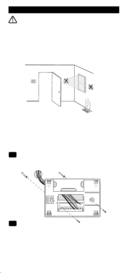
Thermostat Location
Install the thermostat approximately 5 feet (1.5m) above the floor in an
area that has a good amount of air circulation and maintains an average
room temperature.
Avoid installation in locations where the thermostat can be affected by
drafts, dead air spots, hot or cold air ducts, sunlight, appliances, concealed
pipes, chimneys and outside walls.
Install your new TRADEPRO
®
thermostat in 5 basic steps:
1Install the Sub-Base
2Provide Power
3Connect Your Wires
4Set Installer Switches
5Attach Thermostat to Sub-Base
Install the Sub-Base:
• Remove the sub-base from the body of the thermostat.
• Mount the sub-base as shown below:
1
UP UP
Drill 3/16” pilot holes
in your desired location.
Use supplied anchors
for drywall or plaster.
Provide Power
• For 24 Volt AC power, you must connect the common side of the trans-
former to the C terminal on the thermostat sub-base.
• For primary or back-up power, insert the 2 supplied “AA” type alkaline
batteries into the battery compartment located in the rear housing of the
thermostat. Make sure to position the Positive (+) and Negative (-) sides
of the batteries correctly with the +/- symbols in the battery compartment.
2

2
1 HEAT / 1 COOL Single or Dual Transformer
Set Installer Switch to CONV
Rh
24 Volt AC Power (heating transformer) [note 2]
Rc
24 Volt AC Power (cooling transformer) [note 2]
W1 Heat Relay (appears as W1/E on TP-P-521)
Y1 Compressor Relay
G Fan Relay
C 24 Volt AC Transformer Common [note 1, 3]
Typical Wiring Configurations
NOTE: The “Installer Switch” option will be configured in the next step.
Conventional Systems
Connect Your Wires
3
NOTES - Conventional Systems
[1] If batteries are installed the 24 Volt AC common connection is optional
[2] Remove factory installed jumper for dual transformer systems
[3] In dual transformer systems, transformer common must come from
cooling transformer
[4] If needed for system
Provide disconnect and overload protection as required.
2 HEAT / 1 COOL Single or Dual Transformer (TP-P-521)
Set System Type to CONV
Rh
24 Volt AC Power (heating transformer) [note 2]
Rc
24 Volt AC Power (cooling transformer) [note 2]
W1 Heat Relay Stage 1
W2 Heat Relay Stage 2
Y1 Compressor Relay Stage 1
G Fan Relay
C 24 Volt AC Transformer Common [note 1, 3]
Heat Only or Millivolt
Set Installer Switch to CONV
Rh
Power Connection
W Heat Relay (appears as W1/E on TP-P-521)
G Fan Relay [note 4]
C 24 Volt AC Transformer Common [note 1]
3
Factory Setting
Switch Default Options Comments
NOTES - Heat Pump Systems
[1] If batteries are installed the 24 Volt AC common connection is optional.
[2] Select Ofor cool active or B for heat active.
[3] Install a field supplied jumper between the W2 and Eterminals if
there is no separate emergency heat relay installed.
Provide disconnect and overload protection as required.
CONV / HP CONV
F / C F
HE / HG HG
Set Installer Switches
4
CONV Select for conventional systems
HP Select for heat pump systems
F Select for fahrenheit temperature scale
C Select for celsius temperature scale
HG Select for gas heat
HE Select for electric heat
Typical Wiring Configurations
NOTE: The “Installer Switch” option will be configured in the next step.
Heat Pump Systems
1 HEAT / 1 COOL - No Auxiliary Heat
Set Installer Switch to HP
Rh 24 Volt AC Power
Rc Connected to Rh with supplied Jumper Wire
O or B
Changeover Valve [note 2]
Y1 Compressor Relay
GFan Relay
C24 Volt AC Transformer Common [note 1]
2 HEAT / 1 COOL - Including Auxiliary Heat (TP-P-521)
Set Installer Switch to HP
Rh 24 Volt AC Power
Rc Connected to Rh with supplied Jumper Wire
O or B
Changeover Valve [note 2]
Y1
Compressor Relay (1st stage heating/cooling)
W2 Auxiliary Heat Relay (2nd stage heating)
[note 3]
E Emergency Heat Relay [note 3]
G Fan Relay
C 24 Volt AC Transformer Common [note 1]
The Installer switches are located on the back of the thermostat and must
be properly configured for this thermostat to operate properly. The reset
button must be pressed after making any changes to these switches.

4
Attach Thermostat to Sub-Base
5
1. Line up the thermostat body with the sub-base.
2. Carefully push the thermostat body against the sub-base until it snaps
into place.
3. Insert quick reference card into slot on top of thermostat.
3
Setting User Options
Advanced User Options
User options allow you to customize some of your thermostat’s features.
Most users will not need to make any changes to the settings in this section.
To enter the User Options menu, hold down the RETURN button
for
approximately 3 seconds until the screen changes and displays the
first User Option.
Press the or button to change the setting for the displayed User Option.
After you have made your desired setting, press RETURN to advance to the
next User Option.
The thermostat will return to normal mode after your last user option is
made or after no keys have been pressed for 15 seconds.
User Factory Setting
No. Options Default Options Comments
1 1st stage
0.5
0.5, 1.0
Select a 1st stage temperature
differential
or 2.0 differential of .5˚, 1˚ or 2˚F (.2˚, .5˚
or 1˚C)
2 2nd stage
2.0
1.0, 2.0,
Select a 2nd stage temperature
differential
3.0, 4.0
, differential of 1˚, 2˚, 3˚, 4˚, 5˚ or 6˚F
(TP-P-521)
5.0
or
6.0
(.5˚, 1˚, 1.5˚, 2˚, 2.5˚ or 3˚C)
3
LNG
Selects long (permanent) hold mode
24HRS
Selects 24 hr. (temporary) hold mode
4
OFF
Disables filter service monitor feature
30, 60, 90
,Selects a number of days before
120, 180, the thermostat will flash a Service
365 Filter reminder in the display.
5 OF REC Disables adaptive (early)
recovery mode
ON REC Enables adaptive (early)
recovery mode
Table of User Options
Extended
Hold Period
LNG
Filter
Service
Monitor
OFF
Adaptive
Recovery
Mode (ARM
TM
)
OF REC

5
4
Setting Your Program Schedule
Setting the Time and Day
1.
In normal operating mode, press the DAY/TIME
button. The display will switch to the day/time
setting mode and the hour will be flashing.
2. Press or to adjust the hour.
Press DAY/TIME.
3. Press or to adjust the minute.
Press DAY/TIME.
4. Press or to adjust the day of the week. Press RETURN to exit.
Tips Before Setting Your Program Schedule
• Make sure your current time and day of the week are set correctly.
• When programming, make sure the AM and PM indicators are correct.
This thermostat comes pre-programmed with a default energy saving
program. The following table outlines the pre-programmed times and
temperatures for heating and cooling in each of your 4 daily weekday and
weekend events. If you wish to use these settings then no further program-
ming is necessary:
Weekday Weekend
MORN
DAY
EVE
NIGHT
Time: 6:00 pm
Heat: 70˚ F (21˚ C)
Cool: 78˚ F (26˚ C)
Time: 8:00 am
Heat: 62˚ F (17˚ C)
Cool: 85˚ F (29˚ C)
Time: 6:00 am
Heat: 70˚ F (21˚ C)
Cool: 78˚ F (26˚ C)
Time: 10:00 pm
Heat: 62˚ F (17˚ C)
Cool: 82˚ F (28˚ C)
4 Event
Time: 6:00 pm
Heat: 70˚ F (21˚ C)
Cool: 78˚ F (26˚ C)
Time: 8:00 am
Heat: 62˚ F (17˚ C)
Cool: 85˚ F (29˚ C)
Time: 6:00 am
Heat: 70˚ F (21˚ C)
Cool: 78˚ F (26˚ C)
Time: 10:00 pm
Heat: 62˚ F (17˚ C)
Cool: 82˚ F (28˚ C)
Residential 5-2 Day Programming– Weekday/Weekend
Factory Settings
Programming a 5-2 Day Residential Schedule
The 5-2 day residential programming mode allows you to program Monday
- Friday with one 4 event schedule and then allows you to change Saturday
and Sunday with a different 4 event schedule.
1. Press the PROG button. The display will switch
to programming mode.
The days M, TU, W, TH,
and F will be displayed and the hour will
be flashing.
2. Move the SYSTEM switch to either the HEAT
or COOL position.
3. Press the or to adjust the hour for the
MORN (morning) event. Press PROG.
4. Press or to adjust the minute for the MORN event. Press PROG.

6
5. Press or to adjust the temperature for the
MORN event. Press PROG.
6. Repeat steps 3-5 for the DAY, EVE and NIGHT events.
7. Repeat steps 3-6 for the weekend (S, SU) program.
8.
If needed, repeat steps 2-7 to program the opposite mode (HEAT or COOL).
9. Press RETURN to exit.
5
Operating Your Thermostat
Setting the System Control Mode
The System Control has several modes of operation that can be selected by
moving the SYSTEM switch to the appropriate position.
COOL
Only your cooling system will operate
OFF Heating and cooling systems are off
HEAT Only your heating system will operate
Additional Switch Position (Model TP-P-521 Only):
EMER Operates a backup heat source
(Emergency Heat) for heat pump systems only.
NOTE:
If your model TP-P-521 was configured for a conventional system (CONV)
then you will not
have the EMER (emergency heat) option and “NO EMER
SET” will flash in the display if EMER is selected with the system switch.
Setting the Fan Control Mode
The Fan Control has 2 modes of operation – AUTO and ON. The mode can
be selected by moving the FAN switch to the appropriate position.
AUTO The system fan will run only when your
heating or cooling system is running
ON The system fan stays on
Temperature Adjustment
Temporary Adjustment – Press the or button to adjust the current
set point temperature.
Extended Adjustment – Press the HOLD button so that HOLD appears in
the display screen. Press or to adjust the current set temperature.
Status Indicators
Status indicators appear in the display to let you know if your system is
heating, cooling or off.
HEAT ON Indicates that your heating system is running.
COOL ON Indicates that your cooling system is running.
SERVICE Indicates that a user selectable service reminder was selected.
Additional status indicators (Model TP-P-521 Only):
AUX Indicates that the auxiliary stage of heating is running
(multi-stage systems only).
EMER Indicates that the emergency heating system is running (heat
pump systems only).

Program Event Indicators
Program Event Indicators appear in the display to let you know what part of
your current program is active. The 4 different program event indicators are
MORN, DAY, EVE and NIGHT. When the program event indicator is flashing,
your program has been temporarily bypassed and will resume at the next
scheduled event. NOTE: You will not see a program event indicator while in
HOLD Mode.
Resetting the Thermostat
This thermostat provides you with a reset button that will erase all of your
user settings and 5-2 day programming. To reset the thermostat, use a small
object such as a tooth pick or paperclip and gently press the button located
inside the small hole on the front of the thermostat housing labeled “reset”.
6
Additional Operation Features
Compressor Protection
This thermostat includes an automatic compressor protection delay to
avoid potential damage to your system from short cycling. This feature
activates a short delay after turning off the system compressor.
7
Thermostat Maintenance
Changing the Batteries
Depending on your particular installation, this thermostat may be equipped
with two (2) “AA” type alkaline batteries.
If batteries are installed and they
become low, a low battery indicator will appear in the display.
You
should
change your batteries immediately when you see the low battery signal by
following these instructions.
1. Remove thermostat body by gently pulling it from base.
2. Remove old batteries and replace with new batteries.
3. Make sure to correctly position the (+) and (-) symbols.
4. Gently push thermostat body back onto base.
NOTE: We recommend replacing the thermostat batteries annually or if the
thermostat will be unattended for an extended period of time.
Thermostat Cleaning
Never spray any liquid directly on the thermostat. Using a soft damp cloth
wipe the outer body of the thermostat. Never use any abrasive cleansers to
clean your thermostat.
©2018 TRADEPRO • All Rights Reserved • Made in China. TPP-100-01
Store this manual for future reference.
3 Year Limited Warranty
TRADEPRO
®
warrants each new TRADEPRO
®
thermostat against any defects that are
due to faulty material or workmanship. This warranty and our liability does not apply
to batteries, nor does it include damage to merchandise or the thermostat resulting
from accident, alteration, neglect, misuse, improper installation or any other failure
to follow TRADEPRO
®
installation and operating instructions. This limited warranty ap-
plies for the duration of the warranty period from the original date of purchase by a
professional service technician. TRADEPRO
®
agrees to repair or replace at its option
any TRADEPRO
®
thermostat under warranty provided it is returned postage prepaid to
our warranty facility in a padded carton within the warranty period, with proof of the
original date of purchase and a brief description of the malfunction. This limited war-
ranty does not include the cost of removal or re-installation. This warranty gives you
specific legal rights and you may also have other rights that vary from state to state or
province to province. Answers to any questions regarding our limited warranty may be
obtained by writing our corporate offices. For warranty service, please visit your nearest
TRADEPRO
®
facility.
Technical Assistance: 866-268-5599 (U.S.) • 630-844-1968 (Outside the U.S.)

TPP-100-01
This manual suits for next models
1
Table of contents
Other TradePro Thermostat manuals

Popular Thermostat manuals by other brands


McPower
McPower TCU-230 Reference manual

Honeywell
Honeywell VisionPRO IAQ operating manual

White Rodgers
White Rodgers 1F90-51 Operation guide

Eelectron
Eelectron TM11A01KNX quick start guide

Daikin
Daikin Premium Mini D2270 Owner's Manual & Installation Instructions

Uponor
Uponor Climate Control Installation and operation guide