Vitrex FloorWarm FWC300 User manual

FWC300
Version 2.0
TOUCH SCREEN
THERMOSTAT
Consult an electrician prior to installation to ensure room is suitable for underoor heating system,
they will also be able to recommend the best location for the thermostat to be placed.
Read all the instructions before commencing installation.
Before installation of the nished ooring, test the resistance of the heating mat to ensure it is not
damaged. Please test the sensor for resistance before connecting to the thermostat and before the
laying of the nal ooring. The temperature sensor should give a reading of between 7K and 42K
Ohms, if it does not then the sensor is faulty and should be replaced.
PLEASE RETAIN ALL MANUALS FOR FUTURE REFERENCE.
Approved in accordance with:
EN60730-2-9:2002+A2:2005
EN 61000-3-2:2006
EN 61326:1997+A1:1998+A2:2001
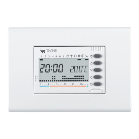
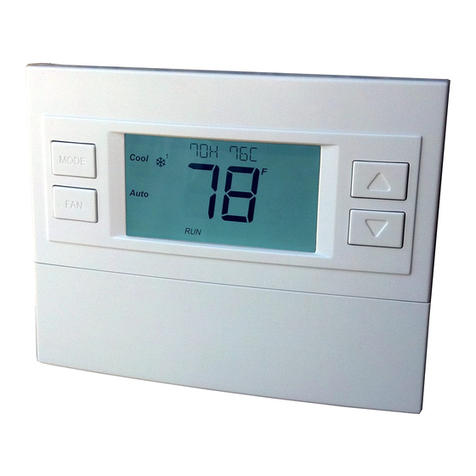
Weekly programmable LCD digital thermostat, this thermostat allows the user to set 6
independent time zones with dierent temperatures; you can also select manual mode
or separate weekday and weekend modes. Only to be used for controlling Floorwarm
underoor heating systems.
TECHNICAL DATA
• Voltage: 230v
• Power consumption: 2W
• Setting range: 5~90°C
• Range Limit: 4~99°C
• Switching dierential: +/- 0.5k
• Ambient temperature: -5~50°C
• IP Grade: IP20
• Housing: Flame retardant PC
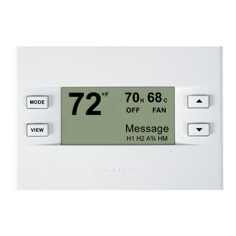
BUTTON DESCRIPTIONS
Menu key
Period from 1 to 6
Clock
On/o switch
Temperature sensor
Heating on
Minus key
Time/temperature display
Measured temperature
Manual mode
Day number
Programming mode
Plus key
Install the sensor between
two heating cables and not
in contact with them.
SENSOR LAYOUT
FUNCTION AND DISPLAY EXPLANATION
WIRING DIAGRAM
FEATURES
• Touchscreen backlit display
• 7 day programmable function (7 days, 5+2 days or 6+1 days)
• Room temperature always on display (even when thermostat is o)
• Frost protection mode
• Adjustable minimum and maximum oor temperature levels
Product may vary from images shown.
IMPORTANT NOTICE:
ENSURE THE MAINS SUPPLY IS ISOLATED PRIORTO INSTALLATION/MAINTANENCE/TESTING
ALL VITREX FLOORWARM UNDERFLOOR HEATING MATS MUST BE EARTHED
A DEDICATED 30mA (RCD) MUST BE USEDWITHTHIS HEATING SYSTEM
ELECTRICAL WORKWHICH IS SUBJECTTO PART P BUILDING REGULATIONS MUST BE CARRIED OUT BY A
QUALIFIED ELECTRICAL CONTRACTOR
ALL WORK MUST CONFORM TO BS 7671.2008 AND THE LATEST IEE WIRING REGULATIONS (CURRENTLY
17th EDITION). CONSULT AN ELECTRICIAN PRIOR TO INSTALLATION TO ENSURE THE ROOM IS SUITABLE
FOR UNDERFLOOR HEATING SYSTEMS
Fitting Your Thermostat
The thermostat should be tted in a position where it is away from both direct sunlight and drafts.
The thermostat should be tted in a single gang mounting box which has a minimum depth of 32mm.
The thermostat must be tted in accordance with the instructions in this manual by a fully qualied
electrician.
Floor Sensor
No Polarity
230V +/- 5% 50Hz 16A
DISPOSAL OF OBSOLETE APPLIANCES
DO NOT dispose of this appliance
in your general waste. Your local
authority or retailer will be able
to provide further guidance.

ADVANCED SETTINGS
• With the thermostat turned o press and hold the ’’ ’’ key whilst simultaneously
switching on the thermostat, this enters the advanced setting mode.
SENSOR ERROR INDICATOR
• Please select the correct sensor mode in“Advanced Settings”. “Err”will be displayed
on the screen if the incorrect mode is set or if the sensor has failed or is not correctly
connected.
1ADJ – TEMPERATURE CALIBRATION
• Press the‘’’’key or‘’’’key to adjust the current measured temperature. The range
for adjustment is +/- 9. 9 °C, then press the menu key to enter the next advanced setting.
25EN - TEMPERATURE SENSOR
• Press the‘’’’key or‘’’’key to select sensor working mode, IN is internal sensor,
OUT is external sensor, ALL is both sensors, then press the menu key to enter the next
advanced setting (This should be set to ALL)
3HI - MAXIMUM FLOOR TEMPERATURE
• Press the‘’’’key or‘’’’key to adjust the temperature value, range limit 5~99°C,
then press the menu key to enter the next advanced setting
• For wood/ laminate ooring we recommend a maximum temperature of 27°C. Check
with the ooring manufacturer to check compatibility with underoor heating)
4LO - MINIMUM FLOOR TEMPERATURE
• Press the‘’’’key or‘’’’key to adjust the temperature value, range limit 4~35°C,
then press the menu key to enter the next advanced setting.
5ADA - ADAPTIVE FUNCTION
• Press the‘’’’key or the‘’’’key to change adaptive function status, then press
the menu key to enter the next advanced setting. (With the function set to ON the
thermostat will pre-heat for 30 minutes.With the function set to OFF, the function
is cancelled.
6PRG - WEEKLY MODE
• Press the‘’’’key or the‘’’’key to change the weekly function status. There are
three modes. If all the day numbers (1 to 7) are showing, then the weekend function
is disabled.
• When day numbers (1 to 5) and (6 to 7) ash alternately, then the weekend programme
is activated on days (6 and 7).
• When day numbers (1 to 6) and day (7) ash alternately, then the weekend function
is only activated on day 7. The weekday function operates from day 1 to 6.
• Press the‘’’’key or‘’’key to selection weekly status then press the menu key
to enter into advanced setting.
7FAC - FACTORY RESET
• Programming parameters will be reset to factory settings when symbol“ - - -“ appears.
8LRP – FROST PROTECTION MODE
• Press the‘’’’key or the‘’’key to change frost protection setting to either on or o,
then press the menu key to enter into the 1st advanced setting, press the on/o key to
exit and save the advanced settings.
FUNCTION AND DISPLAY EXPLANATION
Manual Control Mode
Period Programming Mode Return (am), period 3
Heating On Leave (pm), period 4
Wake Up, period 1 Return (pm), period 5
Leave (am) period 2 Sleep, period 6
PERIOD PROGRAMMING
Press the ’’ ’’ key for 5 seconds to begin programming
Week
Adjust period time
Adjust set temperature
Weekend
DAILY OPERATION
•Menu ’’ ’’
Press the ’’ ’’ key to select manual mode or clock-controlled programme mode,
use the “”or“”key to enter into comfort mode in clock-controlled programme
mode
•Plus “”and minus“”
Press the“”or“”key to increase or decrease your set value
•Clock “ “
To set the time and day, press and hold the“ “ key for 5 seconds. The day symbol
will start blinking, use the“”or“”key to set the day (if you don’t press either
the “”or“”keys within 5 seconds the thermostat automatically exits this
mode), press the“ “ key to conrm the setting. Repeat the above steps to set the
hours and minutes.
•On/o “ ”
Press the“ ”key to switch the thermostat on or o.The set temperature and time
will be displayed alternately. The room temperature is always shown.
•Child lock, press both‘’’’and‘’’’for 5 seconds and the display shows‘‘ ’’
repeat this to unlock the thermostat (‘‘ ’’disappears)
“ ” Manual Mode
The scheduled event program is overriden, set the temperature according
to your individual requirements and the thermostat will operate at this
temperature permanently
“ “ Clock-controlled Programme Mode
The day has been split into 6 events, the thermostat will operate automatically
according to the programmed temperature and time
“ ” & “ “ Comfort Mode
The temperature can be temporarily changed for a single event, the confort
mode temperature is reset at the next event, and the thermostat will return
to the scheduled event program
PERIOD PROGRAMMING(cont.)
Note:
•The pre-programmed setpoint (15°C) for event 3 & 4 is the same as event 2, please reset it
according to your individual requirement
•Symbol “OFF” will be displayed if the setpoint reaches the minimum set value and the
thermostat is switched o in this event
Item Period Period Default Adjust Default Adjust
Symbol Time Temperature
106: 00 20°C
208: 00 15°C
311: 30 15°C
412: 30 15°C
517: 00 22°C
622: 00 15°C
108: 00 22°C
223: 00 15°C

MOUNTING STEPS
Everest Road, Lytham St. Annes, Lancashire, FY8 3AZ, England Tel: +44 (0) 1253 789 180 www.vitrexoorwarm.com
Install the housing cover and lock the external frame
Disassemble external frame with screw driver NOTE: Please take care of the connection wires between the
housing cover and the power base when installing the
thermostat
STEP
1
STEP
2
STEP
4
Install the thermostat in electrical connection box with screws
STEP
3
External frame Housing cover Power base
