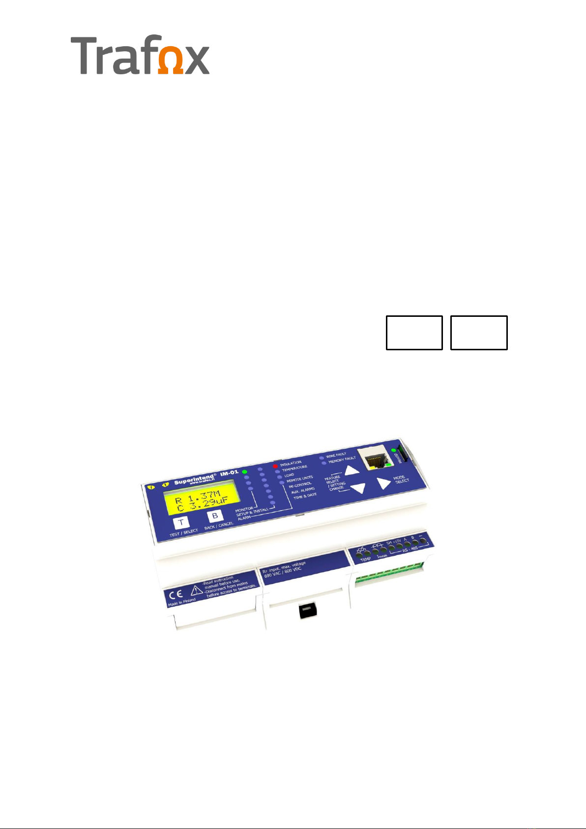
Trafox SUPERINTEND IM-01.MED User manual
Superintend IM-01.MED/IC-01/TC-01/RD-01/PEC-01 Manual v1.15 English
Rights to modify the content reserved
© Copyright Muuntosähkö Oy - Trafox 15.9.2020
SUPERINTEND IM-01.MED/IC-01/TC-01/RD-
01/PEC-01
IMD Insulation Monitoring device for non-grounded (IT) electrical
networks for medical locations
Instructions for installation and use v1.15
AC/DC
MED

2© Copyright Muuntosähkö Oy –Trafox Superintend IMD
http://www.trafox.fi
Table of Contents
INSTRUCTIONS ..................................................................................................4
SYSTEM DESCRIPTION .......................................................................................5
INSTALLATION ...................................................................................................5
PHYSICAL CONNECTION ..................................................................................... 5
DEVICE MOUNTING ............................................................................................ 5
RS-485 NETWORK CONNECTION ......................................................................... 9
HW SETTINGS OF THE TC-01 AND IC-01 UNITS .................................................. 11
HW SETTINGS OF THE RD-01 UNIT .................................................................... 12
HW SETTINGS OF THE PEC-01 UNIT................................................................... 13
HW SETTINGS OF THE IM-01.MED UNIT ............................................................. 13
HW SETTINGS OF THE CLT-01 UNIT ................................................................... 14
SYSTEM CONFIGURATION ................................................................................. 14
USE ..................................................................................................................16
GENERAL ........................................................................................................ 16
IM-01.MED UNIT.............................................................................................. 16
MENU STRUCTURE........................................................................................ 17
MONITOR MENU ........................................................................................... 19
ALARM MENU ............................................................................................... 22
SETUP MENU................................................................................................ 27
NETWORK SCAN........................................................................................... 31
NETWORK VIEW / ADDING AND REMOVING DEVICES ....................................... 34
AUX. ALARM MASK ....................................................................................... 36
IP SETTINGS................................................................................................ 38
ERRORS ...................................................................................................... 39
LOG FILES ................................................................................................... 40
Event log (EVENTLOG.TXT) .......................................................................... 41
Measurement log (MEASLOG.TXT) ................................................................ 47
Setup log (SETUPLOG.TXT) .......................................................................... 48
MODBUS/TCP REMOTE CONTROL.................................................................... 49
REMOTE CONTROL UNITS ................................................................................. 54
INSULATION RESISTANCE REMOTE CONTROL UNIT IC-01 ................................. 54
TRANSFORMER REMOTE ALARM UNIT TC-01 .................................................... 56
INSULATION RESISTANCE AND TRANSFORMER REMOTE ALARM UNIT RD-01....... 57
Monitor mode ............................................................................................. 58
Alarm mode ............................................................................................... 59
System test mode....................................................................................... 60
System fault mode...................................................................................... 60
Setup mode ............................................................................................... 60
PEC-01 UNIT ................................................................................................... 61
CLT-01 UNIT ................................................................................................... 63
TECHNICAL SPECIFICATIONS...........................................................................65
IM-01.MED UNIT.............................................................................................. 65
PEC-01 UNIT ................................................................................................... 67
TC-01 and IC-01 UNITS .................................................................................... 67

Superintend IMD © Copyright Muuntosähkö Oy - Trafox 3
http://www.trafox.fi
RD-01 UNIT .................................................................................................... 67
MECHANICAL DIMENSIONS ............................................................................... 68
QUICK INSTRUCTION TEMPLATES OF IC-01 AND TC-01 FOR MEDICAL LOCATIONS.. 71
QUICK INSTRUCTION TEMPLATE OF RD-01 FOR MEDICAL LOCATIONS ................... 72
IM-01.MED - QUICK INSTRUCTION FOR ACKNOWLEDGING ALARMS ...................... 73

4© Copyright Muuntosähkö Oy –Trafox Superintend IMD
http://www.trafox.fi
INSTRUCTIONS
These instructions for use are intended for trained electrical engineering professionals.
The IM-01.MED and PEC-01 devices are marked with the symbol shown below, which
indicates that if the device has been installed incorrectly or used in violation of
instructions, safety could be jeopardised. The description of the symbol is presented in
this manual instead of on the device due to space constraints. Such sections are marked
with the symbol shown below.
A symbol indicating possible danger. A description of the symbol may be
placed on the device or provided in the instructions for use.

Superintend IMD © Copyright Muuntosähkö Oy - Trafox 5
http://www.trafox.fi
SYSTEM DESCRIPTION
IM-01.MED, PEC-01, TC-01, IC-01, RD-01 and CLT-01 form a system of devices that can
be used to measure and monitor the insulation resistance and capacitance as well as the
continuity of the PE wire of floating electricity networks (Medical IT systems in
accordance with standard IEC 60364-7-710). Of the aforementioned devices, IM-01.MED
is necessary, while the other devices are accessories.
INSTALLATION
PHYSICAL CONNECTION
The devices are connected to the electrical network, which may contain
dangerous voltage. The device may be installed by a trained electrical
engineering professional only. The device contains no user-serviceable parts
and must not be opened. Using the device in violation of these instructions
may compromise safety.
The IM-01.MED unit is the control unit of the system and is installed in the switchboard.
Two IM-01.MED devices may not be installed galvanically in the same network, for
example on the secondary side of the same transformer. The connection is performed as
presented in Figure 1. The installation and wiring should be performed in accordance
with standards IEC 60364 as well as EN 50110. The operating voltage connection of IM-
01.MED must always be equipped with a coupler or a circuit breaker so that the
electricity supply can be disconnected for the duration of maintenance work, for
example. The location of the disconnectors must be clearly marked in the switchboard.
The coupler or line protection switch should also control a relay or contactor, which
separates the measuring wires from the network to be measured. The IM-01.MED device
is equipped with an internal 1 A fuse. In spite of this, the wires of the operating voltage
supply should still be protected with an external fuse. A suitable if the size is, for
example, 6 A. In a DC operating voltage supply, an external Schurter 0001.2503
(T800mA) fuse should be used.
DEVICE MOUNTING
The IM-01.MED, PEC-01 and CLT-01 devices are intended for installation in a DIN TS35
rail in accordance with standard IEC 60715. They are installed by inserting the upper
edge of the DIN TS35 rail in the groove intended for the DIN TS35 rail on the back of the
device and by pushing the bottom edge of the device backward until the retaining latch
clicks into place.

6© Copyright Muuntosähkö Oy –Trafox Superintend IMD
http://www.trafox.fi
The IM-01.MED unit comes with the connections shown in the following table. The
shaded parts are optional and are installed as needed, while installing the other parts is
mandatory.
Category
Connector
Description
Operating
voltage
connection
Protective earth, to be connected to the earthing circuit connector
L
110…240 VAC, 48…62 Hz phase conductor, internal fuse 1A slow
+/-110…300 VDC, use an external fuse Schurter 0001.2503 (T800mA)
N
110…240 VAC neutral conductor
-/+110…300 VDC
RS-485
SH
RS-485 cable shield, internally connected to PE
+12V
+12V output for the TC, IC, RD, PEC and CLT units, current limit 0.5 A, twisted
pair 2
A
RS-485 data+ (two-way data/twisted pair 1)
B
RS-485 data- (two-way data/twisted pair 1)
-
RS-485 network and 12V connection earth, twisted pair 2
Measuring connectors
Imeas
Load current measurement input, to be connected to the S1 terminal of
the current transformer. A 50 mΩ resistance is also installed between
S1–S2.
Measuring range ±1.25Vpk
Imeas
Load current measurement input, to be connected to the S2 terminal of
the current transformer. Internally connected to PE
TEMP
Isolation transformer temperature sensor’s (NTC/PT100) input. Internally connected to PE
TEMP
Isolation transformer temperature sensor’s (NTC/PT100) input. Measuring range 0…2.5VDC
TG
Alarm terminal of protective earth, to be connected to the PE rail
MG
Electronics protective earth, to be connected to the PE rail
M1
Connection 1 of the network to be monitored 1; Max 240VAC/280VDC
M2
Connection 2 of the network to be monitored 1; Max 240VAC/280VDC
Alarm relays
AUX. ALARM NO
AUXiliary alarm relay. NO-COM is an open circuit when the alarm in
inactive and closes when the alarm is active. NC-COM functions in a
reverse manner. Max load 250VAC/3A or 30VDC 1A
AUX. ALARM NC
AUX. ALARM COM
TRF. ALARM NO
Transformer's alarm relay. NO-COM is an open circuit when the alarm in
inactive and closes when the alarm is active. NC-COM functions in a
reverse manner. Max load 250VAC/3A or 30VDC 1A
TRF. ALARM NC
TRF. ALARM COM
INS. ALARM NO
Alarm relay of the insulation resistance. NO-COM is an open circuit when
the alarm in inactive and closes when the alarm is active. NC-COM
functions in a reverse manner. Max load 250VAC/3A or 30VDC 1A
INS. ALARM NC
INS. ALARM COM
The Ethernet cable is connected to the RJ45 connector in the front panel.
Before connecting the device to the local area network,
set the TCP/IP parameters suitable for the LAN
(SETUP→IP Settings).

Superintend IMD © Copyright Muuntosähkö Oy - Trafox 7
http://www.trafox.fi
The PEC-01 units are also installed in the switchboard. The PEC-01 unit comes with the
connections shown in the following table. The shaded parts are optional and are installed
as needed, while installing the other parts is mandatory. The installation is performed as
shown in Figure 1.
Category
Connector
Description
Operating
voltage
connection
L
220…240 VAC, 48…62 Hz phase conductor, internal fuse 80 mA slow
N
220…240 VAC neutral conductor
RS-485
+12V
+12V input for RS-485 with opto isolation, twisted pair 2
A
RS-485 data+ (two-way data/twisted pair 1)
B
RS-485 data- (two-way data/twisted pair 1)
TR
A RS-485 network terminal. Connect a short lead in TR-B if the device is
the last one in the chain.
-
RS-485 network and 12V connection earth, twisted pair 2
SH
The shields of the RS-485 cables are joined together here
Measuring
connectors
PE0
The reference for the earthing resistance measuring connectors, to be connected to the PE rail
PE1
Measuring channels for earthing resistance.
Each channel is connected to the last PE connector in the wall socket chain
with a 2.5mm² wire.
PE2
PE3
PE4
PE5
PE6
The measuring connectors of the PEC-01 units are cabled with 2.5mm² installation wires.
PE0 is connected to the PE rail of the switchboard, and the measuring channels are
connected to the earthing connector of the last wall socket of each wall socket branch.
Thus, the PE wire of each wall socket branch makes a loop, and the PEC-01 unit
measures the resistance of that loop. If there are several PEC-01 units, their PE0 wires
do not need to be in the same point.
The TC-01, IC-01 and RD-01 units are installed in mounting boxes. The units have the
following connections, all of which must be installed. The CLT-01 unit to be installed in
the switchboard has equivalent connections, all of which must always be installed.
RS-485
A
RS-485 data+ (two-way data/twisted pair 1)
B
RS-485 data- (two-way data/twisted pair 1)
-
RS-485 network and 12V connection earth, twisted pair 2
SH
Chaining of the RS-485 cable shield
+12V
+12V input from the IM-01.MED unit, twisted pair 2


Superintend IMD © Copyright Muuntosähkö Oy - Trafox 9
http://www.trafox.fi
RS-485 NETWORK CONNECTION
Each unit type comes with its own address area in the range of 0–15 (IC-01, TC-01,
PEC-01) or in the range of 0-4 (RD-01). The IM-01.MED unit distinguishes between units
of different type in the same address from each other. Although the total number of
addresses is 53, the maximum number of devices that can be connected to one IM-
01.MED device is smaller in practice: it must be ensured that the combined power
consumption of the devices does not exceed the maximum value set for the IM-01.MED
as shown in the table below.
IM-01.MED power supply (12 VDC)
300 mA
Device
Power
consumption (12
VDC)/device
IC-01
8 mA
TC-01
8 mA
RD-01
35 mA
PEC-01
14.5 mA
CLT-01
32 mA
The unit address is set by means of a rotary switch (IC-01, TC-01, PEC-01) or buttons
(RD-01). The IM-01.MED unit has no address settings. It is always the host of the bus, in
other words, it gives the commands to different units and then waits for their answers.
The CLT-01 unit has no address settings either.
The IM-01.MED unit and PEC-01 units are installed in the switchboard and connected to
the mains current. Remote units are installed in mounting boxes. They as well as the
CLT-01 unit to be installed in the switchboard, receive the 12VDC supply electricity from
the IM-01.MED unit.
All units are connected to each other via the RS-485 network. The network must form an
uninterrupted chain, which is open at both ends, and contains no branches. Thus, a
maximum of two RS-485 cables are installed in any unit; in other words, an incoming
and an outgoing cable. A terminator is installed in the first and the last unit by means of
a jumper or wire jumper equipped with the unit. In all other units, the resistance must
be left open. The network units can be physically in any order. If the network is long
(>200 m), it is recommended that the IM-01.MED unit is physically located in the middle
of the chain.
The cable shield is also connected to each unit and connected to protective earth in the
IM-01.MED unit. In other devices, the shields are floating and the connector only acts as
a joining connector between two shields.

10 © Copyright Muuntosähkö Oy –Trafox Superintend IMD
http://www.trafox.fi
The RS-485 connection is made using a 2*2 twisted paired cable equipped with a shield
(e.g. AWG22=0.32 mm²=106 Ω/km). In that case, the maximum length of the chain
from the IM-01.MED unit to the last remote unit is 500 m. If a thinner cable is used, the
allowed length shortens inversely proportionately to the cable resistance. The cable
shield is connected to the SH terminal of each unit. The shield is connected to the
network protective earth in the IM-01.MED unit. In other devices, the shields are floating
and the connector only functions as a joining connector of two shields. The twisted pairs
are connected so that the A–B signals are in one pair and the +12V–earth are in another
pair.
Examples of network connection. In the upper Figure, the IM-01.MED unit is in
the middle of the chain, and in the lower Figure, it is at the end of the chain.
Terminators are installed in the green units.
Checklist for the installation of the bus:
Each unit of the same type must have a unique address.
No more than two RS-485 cables may be installed in any unit. Otherwise, the bus
does not form an uninterrupted chain but has branches.
The shields of the cables are connected to the SH terminal of each unit.

Superintend IMD © Copyright Muuntosähkö Oy - Trafox 11
http://www.trafox.fi
The twisted pairs are connected so that the A–B signals are in one pair and the
+12V–GNDs are in another pair.
A terminator is installed at both ends of the bus, in other words, to those units
that only have one of each wire. The TC-01, IC-01, RD-01, CLT-01 and IM-
01.MED units are equipped with a jumper for this purpose. In the PEC-01 unit,
the terminator is installed by connecting a short wire between the TR and B
terminals.
There is always a terminator in only two devices per chain.
HW SETTINGS OF THE TC-01 AND IC-01 UNITS
The addresses of the TC-01 and IC-01 units are set so that there is only one address per
unit in the range of addresses for either unit type. A TC unit may have the same address
as an IC unit, but no TC unit may have the same address as another TC unit (the same
applies to the IC units). If a TC-01-/IC-01 unit is the first or last device of the bus,
connect the two pins next to the terminal strip to each other with a terminator jumper.
The order of pins in TC-01 and IC-01 is shown in the Figure below.
The device address is set with a rotary switch, shown in the Figure. The addresses
corresponding to the switch texts are: A = 10, B = 11, C = 12, D = 13, E = 14 and F =
15. The other addresses (0–9) function in the manner marked on the switch.
A
B
-
SH
+12V
The pins to be
connected by means of
a terminator jumper

12 © Copyright Muuntosähkö Oy –Trafox Superintend IMD
http://www.trafox.fi
HW SETTINGS OF THE RD-01 UNIT
In RD-01 units, the address is set so that each RD-01 unit has its own individual address
in the range of 0-4. The address is set using buttons, see section INSULATION
RESISTANCE AND TRANSFORMER REMOTE ALARM UNIT RD-01, Setup mode for more
information. If the RD-01 unit is the first or last device of the bus, connect the two pins
next to the terminal strip to each other with a terminator jumper. The order of pins in
RD-01 is shown in the Figure below.
A
B
-
SH
+12V
The pins to be
connected by means of
a terminator jumper

Superintend IMD © Copyright Muuntosähkö Oy - Trafox 13
http://www.trafox.fi
HW SETTINGS OF THE PEC-01 UNIT
In PEC-01 units, the device address is set using a rotary switch as shown in the Figure.
When the switch is at the far counter-clockwise position, the address is 0. In the other
far end, the address is 15. The cover can be removed by using a screwdriver between
the cover and the case to pry the cover loose. The addresses corresponding to the switch
texts are: A = 10, B = 11, C = 12, D = 13, E = 14 and F = 15. The other addresses (0–
9) function in the manner marked on the switch. Each PEC-01 unit must have a unique
address between 0–15. The address may be the same as that of a TC-01 or IC-01 unit.
If a PEC-01 unit is the first or last device of the bus, connect the TR and B pins of the
terminal strip with a wire jumper.
HW SETTINGS OF THE IM-01.MED UNIT
Setting a device address is not necessary in the IM-01.MED unit. If the IM-01.MED unit
is at the end of the bus, a terminator must be connected. The terminator jumper is
located under the centre cover in the location indicated in the Figure. Open the cover by
using a small screwdriver between the cover and the case to pry the cover loose.
Address rotary
switch
To remove the cover:
Pry the cover loose
with a screwdriver
here and remove the
cover
The terminator is set by connecting a short circuit connector between terminal blocks TR and B.
To open the cover: pry the cover loose with a screwdriver here and remove the cover
Terminator jumper

14 © Copyright Muuntosähkö Oy –Trafox Superintend IMD
http://www.trafox.fi
HW SETTINGS OF THE CLT-01 UNIT
Setting a device address is not necessary in the CLT-01 unit. If the CLT-01 unit is at the
end of the bus, a terminator must be connected by changing the location of the
terminator jumper to the left and middle pins. The terminal jumper is under the
connector cover, above the terminal strip, as shown in the Figure. Open the cover by
using a small screwdriver between the cover and the case to pry the cover loose.
SYSTEM CONFIGURATION
The entire system must be configured before use. Configuration is performed from the
IM-01.MED unit. The PEC-01 units do not perform measurements and the IC-01/TC-
01/RD-01 units do not give alarms until the bus has been inspected. This is carried out
with the Network Scan function, which is described separately (the SETUP menu). After
the bus inspection, the IM-01.MED unit displays the type and address of each unit on the
screen. For the PEC-01 units, the number of channels used and the resistance measured
from each channel during bus inspection are also displayed. The user must approve and
verify all measured PE resistances and addresses. The IM-01.MED unit creates a table of
the device addresses and the measured PE resistances, to which future alarm limits will
be proportioned. Special attention should be paid to ensure that two similar units with
the same address have not been connected to the system. The most sensible
configuration order for the settings is as follows:
If a microSD memory card has been connected to the device, enable it
(SETUP→Mem Card: in use) and restart the device.
Set the correct time. (SETUP→Time)
Set the load current measurement and isolation transformer parameters
(SETUP→TranSize, Nom.Cur)
To open the cover: pry the cover loose with a screwdriver here and remove the cover
Terminal jumper not
connected
Terminal jumper
connected

Superintend IMD © Copyright Muuntosähkö Oy - Trafox 15
http://www.trafox.fi
Set the alarm parameters (SETUP→InsLimit, PrInsLim, Temp Lim, TsensTyp (Pt
Calib, if needed), LoadLim, PEalarm%, AlarmDly). Remember to disable TempLim
if temperature measurement has not been connected and to disable LoadLim if
the load current measurement has not been connected.
Set the AUX. ALARM mask (SETUP→AUXalarm), which defines the faults that
cause the AUX. ALARM relay to trigger.
Perform bus scanning using the menu SETUP→Network Scan. ENSURE that all
installed units (IC, TC, RD, PEC) are identified and have the correct addresses,
and that the measured PE resistances correspond to the physical lengths of the
installed earthing wires.
During network scanning, the resistances from all channels of all PEC-01
units connected to the system are measured. Therefore, performing a
Network Scan / Network View is permitted in medical locations only when
there is no activity in the premises to be monitored.
When needed, set the range for CLT-01 unit’s current loop output
(SETUP→LoopCurr)
When needed, set the TCP/IP parameters (SETUP→IP Settings)
A more detailed description of the configuration is provided in the Manual section “SETUP
menu”.

16 © Copyright Muuntosähkö Oy –Trafox Superintend IMD
http://www.trafox.fi
USE
GENERAL
The Superintend IMD MED consists of several separate modules integrating into an
insulation monitoring system through an electronic communication bus. The system
includes the following components:
The IM-01.MED unit is the central unit of the system. It performs most of the
measurements independently and controls the operations of the other units and
the alarm relays. The IM-01.MED unit is installed in the switchboard.
The PEC-01 unit measures the continuity and resistance, if needed, of the
earthing wire of wall socket chains. A maximum of six separate chains to be
monitored can be connected to one unit. The system may contain a maximum of
16 PE units. The PEC-01 unit is installed in the switchboard.
The TC-01 and IC-01 units are alarm units to be installed in the operating
premises. The TC-01 unit gives an alarm of the isolation transformer overload or
over temperature, and the IC-01 unit gives an alarm of insulation errors or a
faulty earth conductor. One system can include 16 of each alarm units.
The RD-01 unit is an alarm unit to be installed in the operating premises. The
unit gives an alarm of the isolation transformer overload or over temperature,
insulation errors or a faulty earth conductor. One system can include 5 RD-01
alarm units.
The CLT-01 unit is a current loop transmitter for insulation resistance with a
standard 0…20 / 4…20 mA current message. It is installed in the switchboard.
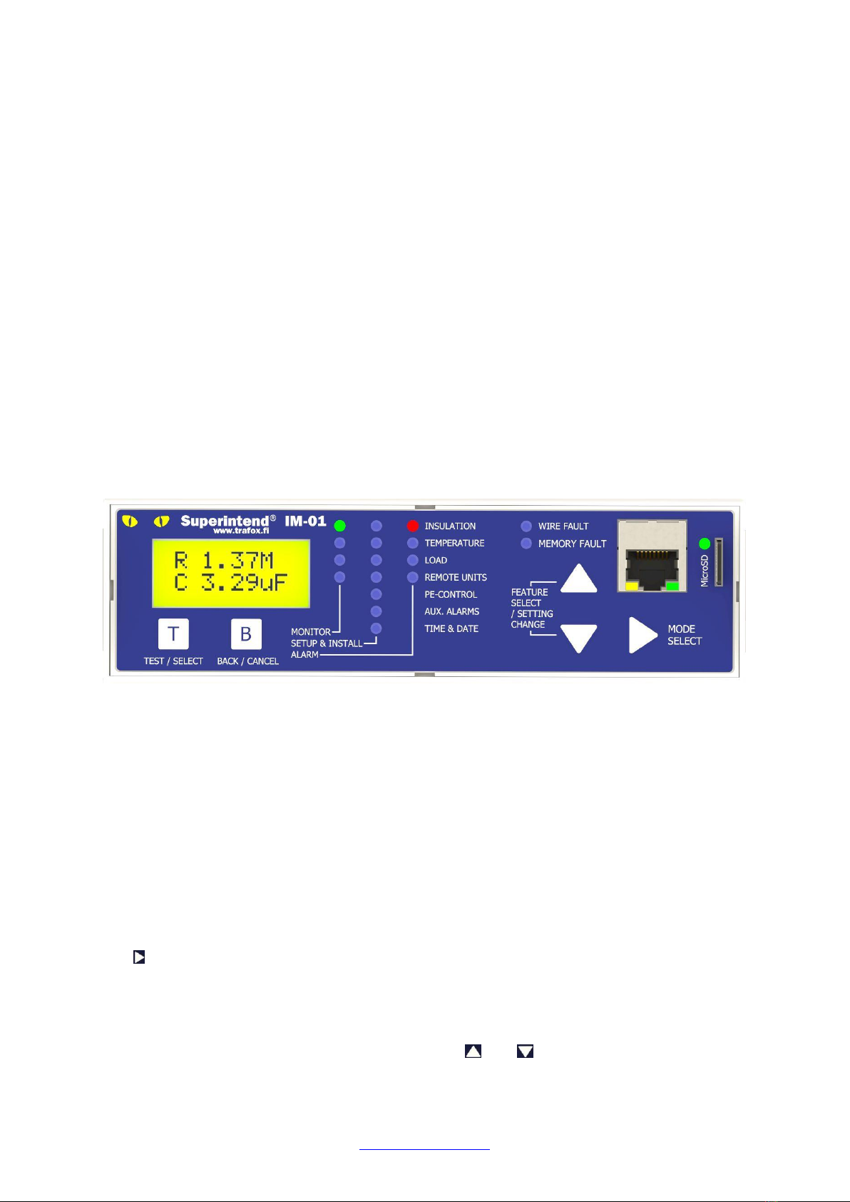
IM-01.MED UNIT
The IM-01.MED unit is the central unit of the system and the master of the RS-485 bus
connected to it. The IM-01.MED contains the user interface of the entire system, and it
controls all TC-01, IC-01, RD-01, PEC-01, and CLT-01 units connected to it. The IM-
01.MED unit continuously reads the measurement results of the PEC-01 units and
determines any fault situations based on them. The error notifications are displayed on
the screen of the IM-01.MED unit and in the TC-01, IC-01 and RD-01 units, and the fault
information can be forwarded to another user-defined system through alarm relays. All
alarm parameters are set through the user interface of the IM-01.MED system.
In addition, the IM-01.MED unit maintains three separate log files on the microSD
memory card if the memory card is inserted in the card slot and enabled in the Setup
menu. They are Excel-compatible text files, which can be transferred to any computer
for more detailed analysis. For more detailed information, see section “Log files”. If the
Superintend IMD © Copyright Muuntosähkö Oy - Trafox 17
http://www.trafox.fi
memory card function is not enabled, only the most recent information of each log entry
is stored in the device memory. The information that is not stored on the memory card
will not be preserved in the memory if the device loses operating voltage.
Measurement values can be monitored and settings can be changed using the
Modbus/TCP protocol via the IM-01.MED unit’s Ethernet connection. For this purpose, the
device RJ45 must be connected to the local area network and the TCP/IP parameters
must have been configured in the Setup menu.
The IM-01.MED unit independently measures the insulation resistance and capacitance of
the IT network to be monitored, in relation to protective earth. The measurement is
performed by feeding two separate low-frequency alternating voltages between the
network and the PE conductor. These generate a low current that travels through the
insulation resistance and capacitance to be measured. The insulation resistance and
capacitance are calculated by measuring the current amplitude and phase. In addition,
the device measures the secondary current and temperature of the isolation transformer
if the current transformer and the NTC/PT100 sensor have been connected to the
measurement couplers reserved for them and have been enabled in the Setup menu.
The system functioning can be tested by pressing the T button of the IM-01.MED unit
when the IM-01.MED unit displays the Monitor menu. The device will test the
functioning of the internal measurement circuit. More detailed information on this is
provided in the description of the Monitor menu.
MENU STRUCTURE
The menus of the IM-01.MED unit have three main levels: MONITOR, SETUP and ALARM.
The button is used to navigate between the main levels when the topmost parameter
of each menu is highlighted on the screen. The first item of the menu is accessed by
pressing the B button at any menu level item. The LED lights, in addition to the LCD
display, indicate the selection in the menu in question.
The menus can be browsed up and down with the and buttons. Access to the
Setup menu is password-protected.

18 © Copyright Muuntosähkö Oy –Trafox Superintend IMD
http://www.trafox.fi
The Monitor menu is the default of the IM-01.MED unit, to which the system returns in
20 minutes after the last time a button was pressed, or after a sufficient number of
presses on the B button in any screen mode.
The Monitor menu mainly has one level. Nearly all information to be displayed can
be viewed by browsing the menu with the and buttons.
The Alarm menu has two levels. The first level displays the reason for the alarm
and the second level shows the alarm start time, the measured parameters, and
alarm limits.
The Setup menu mainly has two levels. The first level displays the valid
parameter, which can be changed on the second level.
Hereafter, the screen modes are called as follows:
The main level of the menu is the topmost menu level (MONITOR, SETUP and
ALARM)
The menu level is the sub-level of the aforementioned, and it is browsed using
the and buttons
The screen mode is the mode following the menu level, and it displays the value
of the parameter/time; also displays a stopped AutoScroll mode. The screen
mode can be accessed from the menu level by pressing the T button.
The AutoScroll mode is in use in the Setup menu items where there are several
parameters to display. In that case, the displayed parameters change every few
seconds. You can stop the display with the and buttons and return from the
screen mode to the AutoScroll mode with the B button. Use the T button to go to
the edit mode or screen mode.
The Edit mode is a Setup menu mode where the parameters to be displayed can
be changed. In the Edit mode, the parameter to be changed flashes and it can be
changed with the and buttons. If there are several parameters to be
changed in the same screen, you can move to the next one by pressing the
button. After the editing is completed, press the T button, after which the values

Superintend IMD © Copyright Muuntosähkö Oy - Trafox 19
http://www.trafox.fi
given must be approved by selecting “Yes” in the Confirm menu and pressing T.
By selecting “No” or pressing the B button in the conformation stage you return
to the previous mode without saving the changes.
As a rule, the buttons function as follows:
Moving to the next parameter on the menu level and screen level. Reduces the
parameter on the edit level. In the AutoScroll mode, stops the display.
Moving to the previous parameter on the menu level and screen level. Increases
the parameter on the edit level. In the AutoScroll mode, stops the display.
Moving to the next menu on the main level. Moves to the next editable
parameter on the edit level.
A general “approval button”. On the menu level, takes you to the AutoScroll or
edit mode. On the edit level, approves the changes made. Pressing the button
in the first three items of the Monitor menu and approving the start of the test
begins the system test.
A general “reject button”. Returns to the previous mode from all modes.
Pressing the B button an appropriate number of times takes you to the default
mode of the main menu (insulation resistance/capacitance) from any mode.
MONITOR MENU
The Monitor menu is the default menu of the IM-01.MED unit during use. All modes of
the menu always return to the topmost item on the Monitor menu after 20 minutes from
the last press of a button.
The following measured parameters are available in the Monitor menu screen:
IT network’s insulation resistance and capacitance in relation to protective earth.
Displayed in kOhms and micro farads.
Temperature of the isolation transformer in degrees.
Secondary current of the isolation transformer. Displayed in a percentage of the
transformer’s nominal current.

20 © Copyright Muuntosähkö Oy –Trafox Superintend IMD
http://www.trafox.fi
The number of the TC-01, IC-01, RD-01 and PEC-01 units configured in the
system and, if needed, the software versions of the units and IM-01.MED.
The manual resistance measurement of the PEC-01 units can be started.
During the manual resistance measurement, test current pulses are fed into
all channels of all PEC-01 units connected to the system. Therefore, the
manual resistance measurement is permitted in medical locations only when
there is no activity in the area to be monitored.
The intensity of the background light can be adjusted to four different levels.
(LOW / MED-LOW / MED-HIGH / HIGH)
Time and date
All fixed alarms can be acknowledged on one go.
The default display is insulation resistance and capacitance. Other parameters and
functions can be viewed by using the and buttons.
The system test is started from the Monitor menu by pressing T and then selecting Y in
the Start test menu and pressing T. This starts the test of the internal measurement
circuit of the IM-01.MED unit. If the test is completed successfully, the screen displays
momentarily the text Test OK; otherwise the text shown in Test FAILED, and an
insulation fault alarm is given to indicate that the insulation resistance can no longer be
measured.
The Monitor menu functions as follows:
This manual suits for next models
4
Table of contents


