Olsen Vet Cart User manual

User’s Manual
Vet Cart


Index
Index ............................................................................................................................................................................3
1 - Introduction............................................................................................................................................................5
2 - Package Contents..................................................................................................................................................5
3 - Equipment Presentation........................................................................................................................................5
- Standard Items.............................................................................................................................................5
- Optional Items ..............................................................................................................................................5
4 - Parts Identification.................................................................................................................................................7
5 - Equipment Description and Operating..................................................................................................................7
- Before Turning On the Equipment...............................................................................................................7
- Turning On the Equipment...........................................................................................................................7
- Base Structure .............................................................................................................................................8
5.3.1 Air Compressor (Optional)....................................................................................................................8
5.3.2 Air Tank Drainage.................................................................................................................................8
5.3.3 - Electrical Panel...................................................................................................................................8
5.3.4 - Pressure Regulator for Instruments ..................................................................................................8
- Double Pedal................................................................................................................................................8
- Working Table...............................................................................................................................................9
5.5.1 - Handpieces Arrangement on the Working Table ..............................................................................9
5.5.2 - Panels .............................................................................................................................................. 10
- Pneumatic Handpiece Couplings ............................................................................................................. 10
- Optical Fiber Handpiece (Optional) ......................................................................................................... 11
- Prophylaxis System (Optional) .................................................................................................................. 11
5.8.1 - Bicarbonate Jet................................................................................................................................ 11
5.8.2 - Prophy-Jet (Optional) ....................................................................................................................... 11
5.8.3 - Bicarbonate Jet and Prophy-Jet Use Precautions .......................................................................... 11
- Curing Light (Optional) .............................................................................................................................. 12
5.9.1 - Precautions on the Curing Light Use .............................................................................................. 12
- Ultrasonic Scaler with LED Light (Optional) ........................................................................................... 13
5.10.1 - Ultrasonic Scaler Tips ................................................................................................................... 13
5.10.2 - Ultrasonic Scaler Operating Precautions ..................................................................................... 14
- Electrical Micromotor (Optional)............................................................................................................. 14
5.11.1 - Brushless Electric Micromotor (Optional) .................................................................................... 15
- 3-Way Syringe (Optional) ........................................................................................................................ 16
- Venturi Saliva Ejector (Optional)............................................................................................................. 16
- Vórtive High Power Saliva Ejector (Optional).......................................................................................... 16

- Vacuum Pump Adaptor (Optional).......................................................................................................... 16
- Air Jet (Optional)...................................................................................................................................... 17
- X-Ray Viewer............................................................................................................................................ 17
6 - General Features ................................................................................................................................................ 17
- Valves ........................................................................................................................................................ 17
7 - Installation Requirements .................................................................................................................................. 17
- Pre-Installation .......................................................................................................................................... 17
- Water for the Water Tank.......................................................................................................................... 18
- Electrical Installation................................................................................................................................. 18
8 - Installation........................................................................................................................................................... 18
- Check List .................................................................................................................................................. 18
- Olsen Accredited Technical Assistance Network ..................................................................................... 19
9 - Cleaning and Disinfection................................................................................................................................... 19
- Painted Parts............................................................................................................................................. 19
- Sterilization by Autoclave.......................................................................................................................... 19
- Curing Light ............................................................................................................................................... 20
- Ultrasonic Scaler ....................................................................................................................................... 20
- Saliva Ejectors and Solids Collector ......................................................................................................... 20
- Daily Procedure at Working Day ............................................................................................................... 20
10 - Technical Features ........................................................................................................................................... 21
- Applied Parts........................................................................................................................................... 22
- Accessories and Detachable Parts ........................................................................................................ 22
11 –Symbology........................................................................................................................................................ 23
12 –Dimensional..................................................................................................................................................... 25
13 - Important Notes................................................................................................................................................ 26
- General Cares - Compulsory Reading .................................................................................................... 26
- Disposal................................................................................................................................................... 27
- Transport and Storage............................................................................................................................ 27
- Contraindications.................................................................................................................................... 27
13.4.1 - Contraindications on the Ultrasonic Scaler Use .......................................................................... 27
13.4.2 Curing Light Contraindications ....................................................................................................... 27
14 - Troubleshooting................................................................................................................................................ 28
15 - Preventive Review ............................................................................................................................................ 29
16 - Registro de Revisão.......................................................................................................................................... 30
17 - Warranty Terms ................................................................................................................................................ 30
18 - Message from the President............................................................................................................................ 31

5
1- Introduction
Congratulations for the great choice!
You have acquired high-tech equipment developed to offer the best performance in veterinary procedures
ensuring efficiency and safety for the professional and the patient.
The User Manual presents the descriptive and technical information, installation instructions,
maintenance, cleaning, precautions for use and regulatory guidelines. So before starting the operation of the
equipment read carefully its instructions.
2- Package Contents
Check out the equipment package contents:
Standard Items:
1 Vet Cart
1 User Manual Vet Cart
Optional Items:
Electrical Micromotor
Brushlesss Electrical Micromotor
Ultrasonic Scaler with LED Light
LED Curing Light
Prophy-Jet System
Note:
1 -Items availability in the packaging may change in the case of the customer order.
2 -Handpieces: Dental instruments acquired with the equipment described in the purchase order and invoice of
the product, according to customer request.
3- Equipment Presentation
- Standard Items
Stainless Steel Tray
Polyurethane Casters
- Optional Items
Coupling for Low-speed with Cooling
Midwest Coupling
Coupling for Optical Fiber Handpiece
Additional Handpiece Coupling
Prophylaxis System with Bicarbonate Jet
Prophy-Jet System
Air Jet System
Thermo Comfort System
Coupling for Low-speed Handpiece without
cooling
Coupling for High-speed Handpiece
3-Way Syringe
Instruments Water Tank with Solids Filter
Venturi Saliva Ejector
Pressure Regulator for Instruments
Pressure Gauge for Air Tank
Electrical Micromotor
Brushless Electrical Micromotor
Ultrasonic Scaler with LED Light
LED Curing Light
High Power Vórtice Saliva Ejector
Vacuum Pump Adaptor Set
X-Ray Viewer

7
4- Parts Identification
A - Working Table
(Item 5.5 - pg. 9)
B - Electrical Panel
(Item 5.5.2 - pg. 10)
C -Control Panel
(Item 5.5.2 –pg. 10)
D - Water Tank
(Item 5.2 - pág. 7)
E -Base Structure
(Item 5.3.2 - pág. 8)
F - Progressive Foot Pedal
(Item 5.4 - pg. 8)
5- Equipment Description and Operating
The cart system provides working table handpieces and accessories on a steel base with casters, which
provides mobility for the professional.
It is equipped with air compressor (optional) to supply the compressed air needs of the pneumatic
instruments and saliva ejector Venturi. Its air reservoir is the equipment's column.
Can be moved easily because it has high resistance casters built in molded polyurethane that protect the
floor and have very low noise level in the displacement.
- Before Turning On the Equipment
1º - Check if the equipment is properly installed in accordance to the instructions
in the Chapter 7 (Installation Requirements) of this manual;
2º - If it has sewage tank (2), check if is properly attached and without leaks;
3º - Turn On the equipment's power circuit breaker.
- Turning On the Equipment
1º - Turn On the On/Off switch (4);
2º - If it has compressor, close the pressure valve (1);
3º - Remove the water tank (3) and fill it with filtered and boiled drinking water, up
to the indicated limit in the tank. Then put the tank to the platform. It is
possible to use prophylactic products of low concentration;
4º - If it has compressor, open the pressure valve (1) and check if the water tank
(3) is well attached and free of leaks;
5º - Before starting the use equipment, verify the operation of all instruments and commands
available and perform the cleaning and sterilization of the instruments (chapter 9 –
Cleaning and Disinfection) of this manual.

8
- Base Structure
5.3.1 Air Compressor (Optional)
The cart may come with a compact compressor (7) (optional) to
supply the compressed air needs of the pneumatic instruments and
saliva ejector.
The compressed air tank is the column and base (1) of the
equipment, which has a electrical panel (4), manometer (2), drain (6) and
safety valve (3).
The compressed air outlet has an pressure regulator for
instruments with adjustment valve (5) that allows the reduction and cut
off the airflow. For this adjustment, simply turn the valve clockwise to
reduce or close the flow and counterclockwise to open.
Reducing the airflow in the automatic drain adjustment valve can impair the performance of
pneumatic and ejection instruments.
5.3.2 Air Tank Drainage
The air tank drain (8) is a preventive procedure, which avoids the
moisture accumulation, the automatic drain clogging and consequently a drop
in the performance of pneumatic and ejection instruments.
To drain the air tank: with the compressor turned Off and the air tank
pressurized, open the air tank drain valve (8) by turning it counterclockwise.
Leave the hose outlet free to let out the debris/water until the tank is clean.
Note: When the equipment remains On for a certain period, it is
recommended to drain the tank daily.
5.3.3 - Electrical Panel
4 -On/Off Switch
5 -Voltmeter
6 -Fuses
5.3.4 - Pressure Regulator for Instruments
The pressure regulator for instruments (6) has a filter for blocking the moisture of the
compressed air and a pressure relief valve (5) to protect the equipment pneumatic system. It
is installed on the equipment compressed air outlet.
Its function is to regulate the pressure supplied to the handpieces and to filter, to avoid
dirt on the instruments
Automatic drainage occurs whenever the compressed air network is depressurized or
reaches a pressure of less than 30 PSI, preventing the instruments from working properly.
–Progressive Foot Pedal
The progressive foot pedal is used to drive the handpieces such as the
micromotor, the high-speed handpiece, and the ultrasonic scaler.
When pressing the progressive valve, the higher the pressure on the pedal, the
higher will be the handpiece rotation speed.
Note:for the ultrasonic scaler, the pedal only turns it On and Off.

9
- Working Table
1 -Electrical Panel;
2 -Control Panel;
3 -Instruments Holder;
4 -Bicarbonate Reservoir;
5 -Stainless Steel Tray;
6 -Fiber Optics/Air Jet On/Off Button;
The working table’s function is to provide
handpieces for performing veterinary procedures.
The handpieces are arranged in holders (3) and has composed of stainless-steel tray, 3-way syringe, and
couplings for low and high-speed for pneumatic handpieces.
The layout of the controls may vary according customer order and available handpieces.
5.5.1 - Handpieces Arrangement on the Working Table
As standard, the working tables have the first pneumatic coupling
from left to right for the low-speed handpiece/pneumatic micromotor (1)
and the other couplings are for the high-speed handpieces (4).
The 3-Way Syringe (5) is placed on the last holder on the right.
This standard does not apply when the working table features
built-in bicarbonate reservoir (3). In this case, the first pneumatic
coupling is for the bicarbonate jet handpiece (2) and the second is for
the low-speed handpiece (1). The other couplings are for the high-speed
handpieces.
Note: Do not use high-speed handpieces on low-speed handpiece
couplings. This will damage the handpieces.

10
5.5.2 - Panels
Command Panel Models
Some functions indicated on control panel may not be available according to the equipment
configuration (e.g.: endo function switch)
- Pneumatic Handpiece Couplings
As a standard, Olsen uses the Borden terminal system in its
equipment, making the Midwest system available as an option.
The Borden coupling without cooling (1) is used only for the low-
speed handpiece coupling.
The Borden refrigerated terminal (2) enables spray adjustment
and is an optional item as well as the Midwest (3) terminal which is also
cooled and has a propulsion air return system that does not return to
the user's hand. These terminals do not have ledges or jambs, providing
greater comfort to the user, and can be dismantled for cleaning without
the use of specific tools.
The optical fiber handpiece coupling (4) is optionally supplied with
special Midwest coupling with 3.1 V output for handpieces with
optical fiber lighting.
Note: The pneumatic system is set to allow enough
pressure for the activation of only one pneumatic
handpiece at a time. If any handpiece is not properly seated in
its holder, the propulsion air may partially activate this handpiece,
impairing the equipment’s performance.
Operation instructions:
Connect the handpiece (6) to the coupling by attaching it to the coupling ring (7), ensuring that it is properly
connected and that there is no leakage of air or water.
To activate the rotation: Press the progressive pedal (5). The higher the pressure applied to the button, the
higher the rotational speed of the handpiece.
To adjust the spray: Turn the adjusting ring (9) until the desired volume of water. To adjust the maximum
flow of water, bring the spray adjustment indicators (8) closer to each other. To decrease the flow of water, rotate
X - Ray Viewer
1 - X-Ray Viewer
2 - X-Ray Viewer On/Off Command
1 -Speed Adjustment for Electrical Micromotor
2 -Electrical Micromotor’s Rotation Direction Control
3 -Ultrasonic Scaler Intensity Control and Endo
Function Switch
4 -Ultrasonic Scaler Water Control
5 - Optical Fiber Water Control
Instruments Control Panel:
Standard

11
the ring so it distances one indicator from the other. The completely opposite points indicate the minimum water
regulation for the spray.
Note: the spray adjustment is not available to pneumatic coupling without refrigeration.
- Optical Fiber Handpiece (Optional)
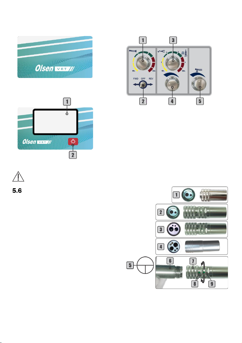
Connect the optical fiber handpiece to the coupling by attaching
it to the coupling ring (1), ensuring that it is properly connected and
that there is no leakage of air or water.
To activate the rotation: Press the progressive pedal (2). The
higher the pressure applied to the progressive pedal, the higher the
rotational speed of the handpiece.
To turn the coupling’s light On/Off: Use the On/Off optical fiber
light switch (3) on the command panel of the working table.
To adjust the spray: Use the optical fiber water control knob (4) on
the instrument control panel.
- Prophylaxis System (Optional)
5.8.1 - Bicarbonate Jet
Prophylaxis equipment by application of
bicarbonate jet, located on the assistant module
or on the working table. Besides the handpiece (2), it is
equipped with a bicarbonate reservoir (4) and a water vapor
filter (3) with drains built-in.
The bicarbonate reservoir (4) has a red line that
determines the limit for filling with sodium bicarbonate.
To activate/deactivate: Press the progressive pedal (1).
The higher the pressure applied to the progressive pedal, the
higher the air volume of the jet emitted by the bicarbonate jet.
5.8.2 - Prophy-Jet (Optional)
Prophy-Jet (6) is a bicarbonate jet instrument with a
built-in reservoir (7) and removable tip (5).
To use it, open the reservoir (7) and put bicarbonate
up to the middle of the compartment (approximately 15 g).
Close the reservoir and install it at the pneumatic
micromotor coupling on the working table.
Before starting the Prophy-Jet (6) use, deposit up to 15g of sodium bicarbonate for dental use in the sodium
bicarbonate reservoir (7) and attach the Prophy-Jet to the pneumatic coupling available on the pneumatic
micromotor on the working table.
To activate/deactivate: Press the progressive pedal (1). The higher the pressure applied to the progressive
pedal, the higher the air volume of the jet emitted by the Prophy-Jet.
Clean the sodium bicarbonate tank at the end of each procedure.
5.8.3 - Bicarbonate Jet and Prophy-Jet Use Precautions
−Do not fill bicarbonate reservoirs with more than the indicated amount. Excessive amounts of bicarbonate
may impair the performance and function of the device;
−When handling sodium bicarbonate, keep the room ventilated and avoid powder inhalation, while filling
the reservoir or using the bicarbonate jet. In the case of inhalation, go to a ventilated place;
−To reduce the risk of inhalation of bicarbonate mist use the Venturi saliva ejector or high power Vórtice
saliva ejector when using the bicarbonate jet;
−Use only sodium bicarbonate for dental use, which can be purchased in any dental stores.

12
- Curing Light (Optional)
This tool was developed for polymerization
and can be used for tooth bleaching. the curing
light produces light radiation to solidify light
sensitive resins with short duration shots.
Technical Features:
−Dimensions: 26 x 25 x 260 mm;
−Wave length: 420-480 nm;
−Net Weight: 135 g;
−Operation: Continuous, ramp and pulse;
−Light intensity with optical fiber tip: 1000 - 1200 mW/cm² (optical fiber tip).
This instrument has a 20 seconds timer for continuous use and protection
mode to prevent overheating. If the curing lights triggered for several consecutive
times without interval, the protection mode will be activated, locking the device for
20 seconds after each drive. To disable the protection mode, allow the device to
stand for 4 minutes. The protection mode can be activated automatically from 9
successive starts.
The curing light uses a beep to indicate the following situations:
1 -Activation of Selection button;
2 -Activation of the ON/OFF button;
3 -After operation for 10 seconds;
4 -After operation for 20 seconds.
Before starting the curing light use, install the optical fiber tip (1) and the light hood (2).
To install the tip: first, attach the light hood (2) to the tip and then attach it to the curing light unit (3). The
tip must be pushed all the way to the fitting end.
To activate/deactivate the curing light: Press the On/Off switch (5) twice. The activation LED (4) will light
up. The curing light unit will run for 20 seconds and will turn Off automatically.
To toggle the operating mode: Each tap on the selection button (9) switches the operation mode. Press the
selection button (9) until the orange LED indicates the desired mode.
The curing light operates in the following modes:
Continuous (6): LED on the maximum power for 20 seconds;
Ramp (7): LED activates at its minimum power, gradually increasing. In 5 seconds reaches its maximum
power until the cycle of 20 seconds is finished;
Pulse (8): LED keeps blinking for 20 seconds.
5.9.1 - Precautions on the Curing Light Use
−Prohibited the use in patients who present biological reactions of sensitivity to light;
−Do not aim the light of the curing light directly at the eyes. The curing light produces optical radiation
emitted by LED;
−Do not touch the tip directly on the curing material. This will prevent material adhering to the tip, impairing
the device performance;
−Do not use the curing light without the light hood;
−The optical fiber tip should only be used on the teeth. Avoid touching the patient's gums, lips or skin;
−Use the curing light only on the teeth;
−After 40 seconds of continuous use, the tip end can reach 56º C;
−Consecutive activations of the curing light with optical fiber tip may cause the tip end to heat, reaching a
maximum temperature of 68º C.

13
- Ultrasonic Scaler with LED Light (Optional)
The ultrasonic scaler has an ultrasonic
generator electronic board that, through the
Piezoelectric System, provides the tip vibration,
giving a high-frequency condition. When the
ultrasonic scaler is triggered, it starts the tip
vibration, activates the LED and opens the water
passage for cooling. Vibration power and water
flow control for cooling can be adjusted through
individual controls.
This handpiece was developed for use in
dental applications, such as scarification, root
planning, root canal treatment, cavity and
periodontal preparation. These tips come with
the ultrasonic scaler: GD1, PD1 and PD3.
Technical Features:
−Frequency: 28 KHz ± 3 KHz;
−Power supply: 24 VCC;
−Output force (half-displacement): <2N;
−Power Rating: 3 to 20 W;
−Operation mode: Continuous;
−Tip vibration displacement: ≤100 μm.
For the ultrasonic scaler use it is necessary to connect the transducer (1) to the terminal (3) and install the
ultrasonic tip on the transducer.
To attach the transducer to the terminal: Align the adjustment indicators (2) of the two parts and carefully
insert them.
To install the scaler tips: Insert the tip into the transducer by threading it carefully, then insert the Torque
wrench (4) into the tip and then rotate it clockwise until it is tight. To remove the tip, turn it counterclockwise with
the Torque wrench.
After installing the tip, check for leakage between the transducer (1) and the terminal (3).
To install a file adapter (not supplied with the scaler): Attach the
adapter to the transducer and screw it gently. Use the Endo wrench
(5) to lock. Insert the file into the tip of the adapter, thread the tip and
then use the Endo wrench (5) to tighten. To remove the adapter, use
the Endo wrench to loosen it and then carefully unscrew.
To activate the ultrasonic scaler: Press the progressive pedal (6).
To adjust the vibration power: Turn the control knob (7) until the desired power is
reached.
To toggle functions: Push the control knob (7) in direction of the table for "GP"
function (General and Perio). Pull the knob gently in the opposite direction of the table
for "E" (Endo) function (this function is not available to V2 Scaler without LED light).
To adjust the water flow: Turn the adjust knob (8) until the desired flow is reached.
The selection between General and Perio / Endo function is not available to V2 Scaler without LED
light.
5.10.1 - Ultrasonic Scaler Tips
The tips GD1, PD1 and PD3 accompany the scaler. The power and application information for each tip is
available in the table below.

14
Note:
1 -Do not use the tip on features other than those specified by the manufacturer.
2 -Do not exceed the power limit for each tip. That could damage the tip and the ultrasonic scaler.
5.10.2 - Ultrasonic Scaler Operating Precautions
−Check out the vibration outside the patient's oral cavity before use. If any abnormality is found, discontinue
use immediately and contact a Certified Olsen Assistance;
−Always use gloves when handling the ultrasonic scaler, tips, Torque wrench and its removable covers;
−Use only the Torque wrench to fix and remove tips. If the tip is not fixed properly, it will present vibration loss;
−This ultrasonic scaler has been developed for professional dental use only and should not be used for any
other purpose;
−The tip wears out with use, this can cause reduction of power. If this occurs, replace the tip;
−Do not sharpen or bend the tip. Tips can be damaged and do not generate enough vibration during
scarification;
−While in use, the ultrasonic scaler system may affect computers and LAN cables. During an operation next to
radio device, interference may be heard;
−Use only autoclave proper for dental use to sterilize tips, Torque wrenches, transducer and LED;
−Before installing any tip on the ultrasonic scaler, check its maximum intensity power. Using power above
recommended will cause tip damage and ultrasonic scaler;
−Keep it away from patients with cardiac pacemakers or anesthetized;
−During the ultrasonic scaler use, the tip temperature may rise if the spray is not used. Always use enough
spray water for the cooling of the handpiece and the teeth;
−Use the device only on the teeth. Contact with skin, gums and mucous membranes may cause injury;
−Keep the ultrasonic scaler away from explosives and flammable materials;
−Do not submit the handpiece to any strong impact, or drop it;
−Do not exceed the recommended intensity for the tip this may damage the tooth and tips;
−Do not use it on metal, or ceramic, porcelain or resin prostheses;
−Do not touch and do not wet the back of the transducer, where there are electrical connections to the power
cord. This can result in electric shock;
−Do not force the ultrasonic scaler cable when remove it. This may cause disconnection.
- Electrical Micromotor (Optional)
The Olsen’s electrical micromotor does
not require a cooling system because it has a
speed control and forward/reverse direction
control.
Technical Features:
−Rotation: from 0 to 35.000 RPM;
−Torque: 270 g-cm;
−Power supply: 24 VCC;
−Max Power: 60 W.
Before starting the operation, connect the handpiece to
the electrical micromotor (2).
To activate the rotation: Press the progressive pedal (1).
To adjust the speed: Turn the control knob (3) until the desired speed is reached.
To change the rotation direction: Use the rotation direction control (4).
FWD: Clockwise. OFF: Off. REV: Counterclockwise.
Note: To change the rotation direction, wait for the electrical micromotor to stop turning completely.

15
5.11.1 - Brushless Electric Micromotor (Optional)
Technical Features:
−- Power Supply: 24 VCA;
−- Power Rating: ~33 W.
−- Rotation Speed:
a) 20:1 from 100 to 2.000 rpm;
b) 1:1 from 2.000 rpm to 40.000 rpm;
c) 1:5 from 10.000 to 200.000 rpm;
−- Torque: ~3,5 Ncm;
−- LED: 25.000 Lux.
−
Before starting the operation, connect the
handpiece to the electrical micromotor (15).
To activate the rotation: press the
propulsion/activation pedal (section 5.5) or the
Manual Start key (11). The On/Off indicator (2) will
turn blue.
To select a preset program: use the Program
key (8). There is 7 programs available, according the
table below:
The selected program is shown on the display (1).
To record program: select program P1 or P2, then select the
desired gear ration and adjust the speed. Press and hold the Program key
(8) until the confirmation of the system.
To adjust speed: use the adjustment keys (13) to increase or
decrease speed. Please see the table below for speed range for each
gear ration value.
The selected speed is shown on the display (5).
To select the gear ratio: use Gear Ratio key (10). There are the
following values available: 1:5, 1:1, 4:1, 10:1, 16:1 and 20:1.
The selected gear ratio is shown on the display (4).
To change the rotation direction: use the Direction key (9). he
selected direction is shown on the display (3).
To adjust the micromotor water: use the water control knob (15) on
the instruments control panel.
To access setup menu: press and hold the Setting key (12).
Use the Setting key (12) to select the desired option.
To adjust LED options: use the adjustment keys (13) to set the
parameter.
To adjust pneumatic activation mode: use the adjustment keys (13) to set the parameter. The selected
pneumatic activation method is shown on the display (6).
LED
Off
LED On
without
delay
LED On
with 10s
delay
When pedal is pressed micromotor
performs the maximum speed
adjusted
Micromotor performs speed according
to the pressure on the pedal
Forward
Reverse

16
To adjust input pneumatic pressure: use the adjustment keys (13) to set the parameter.
Note: the micromotor system preset by the factory according to the internal equipment pressure. It is not
recommended to change the pressure parameters.
- 3-Way Syringe (Optional)
Before beginning the use of the 3-way syringe (5), connect the
syringe tip (3) by pressing the locking ring (4) into the correct fit.
To emit air jet: Press the Air button (1).
To emit water: Press the Water button (2).
To emit spray jet: Press simultaneously the Water and Air buttons.
- Venturi Saliva Ejector (Optional)
The Venturi device (1) uses the compressed air from the air
compressor to generate suction. It allows the coupling of 6,5 mm and
9,5 mm cannulas through the cannula adapters (3) and has a solids
collector (2) to contain solid debris.
As an optional item can be installed to the Venturi saliva ejector’s
hose a quick hitch (4) for an easier removal for cleaning.
Note: The quick hitch is an optional item that can be installed to any hoses
of the Venturi and Vórtice ejectors.
To activate the suction: Remove the ejector (2) from the holder (1).
To deactivate the suction: Place the ejector (2) in its holder (1).
- Vórtive High Power Saliva Ejector (Optional)
The Vórtice high power saliva ejector is a device that uses
the Venturi saliva ejector system, but its volume capacity is
superior to that of the Venturi, reaching up to 385 mm/Hg.
The Vórtice high power saliva ejector may be used for
suctioning in minor surgical and prophylaxis procedures.
To enable/disable suction of the Vórtice saliva ejector (2): use the On/Off button (1).
- Vacuum Pump Adaptor (Optional)
Set minimum activation pressure
from 0.03 to 0.10 MPa
Set maximum input pressure
from 0.20 to 0.40 MPa

17
This item enables the use of the vacuum pump as a suction device.
The suction holder is provided with a device for automatic ignition and
shutdown of the pump. Furthermore, the handpiece has suction flow
control and adapters for use with 9,5 mm. The adapter tip is cannula
removable (1), allowing the use of cannulas of 11 mm.
To activate suction: Remove the vacuum pump suction (2) from its
holder (2).
To adjust suction flow: To decrease the suction flow, turn adaptor's
body (3), where the blue dots (4) alignment indicates the total opening of
the ejection and, the opposite points indicate the closing of ejection.
To deactivate the suction: Place the vacuum pump in its holder (2).
The vacuum pump and cannulas do not come with this device.
- Air Jet (Optional)
The Air Jet system provides agility in procedures with a high-speed turbine. It consists
of continuous air jet through the turbine itself, eliminating the use of a syringe for this function.
Activation through command at the working table.
To activate/deactivate the Air Jet system: press the button (1) on the left side of the
working table (Air Jet and fiber optic are thrown together).
- X-Ray Viewer
The x-ray viewer is an LED illumination display, that allows you to view x-rays without
the need to move away from the patient.
To turn the X-ray viewer, press the On/Off button (1)
6- General Features
−Mechanical structure: Manufactured in SAE 1020 rolled steel profiles and welded by MIG process, to
guarantee the strength and durability;
−Electrostatic painting: It is applied to all structural metal parts of the equipment. The special polyurethane
paint provides the equipment with high durability coating and has antibacterial properties according
to JIS Z 2801: 2000, where in 24 hours, the bacterial reduction is greater than 99.9%.
−Plastic covers: Made of high-strength ABS with acrylic cover, the fairings do not require painting and allow
polishing;
−Electrical system: The equipment can work in frequencies of 50 or 60 Hz and can be configured to be
connected to the voltages of 127/220 Volts by an authorized technician. The maximum supply voltage
of electronic boards, motors, and other controls is 24 V. The electrical system has On/Off switch, and
protection fuses;
−Handpiece holders: Built in ABS, they have vanes to activate the valve of the holder, which interrupts the
operation of the instrument when it is placed in its respective holder.
- Valves
The valves used in the equipment’s hydro-pneumatic system have been developed to ensure its
performance and durability, built in nonferrous metal with chromium coating.
−Command valves: Releases spray to the pneumatic handpiece, with a piston system to achieve stagnation
and non-retraction of water;
−Pressure regulating valves: Guarantee the stability of propulsion pressure of the instruments, also
allowing the adjustment according to the specifications of the handpieces. The factory setting is 2,2
bar of air pressure and regulated flow of 35 to 55 Liters of air per minute;
−Handpiece holder valves: Also called pilot valves, they release or interrupt the propulsion air to the
handpiece when it is removed from the holder.
7- Installation Requirements
- Pre-Installation
The pre-installation is the suitability of the environment for the installation of the equipment. This step
should be guided by Olsen authorized assistance to ensure that the installation environment is suitable to receive

18
the new equipment. In this step should be prepared all water, compressed air, sewage tank, power supply and
other accessories that will interact with the equipment.
Note: This equipment is not designed to be installed or operated in a surgical center.
- Water for the Water Tank
The ideal pressure for the equipment water supply is 2.8 to 6.0 bar.
The recommended pH (Potential of Hydrogen) is between 6.5 and 8.
The water used in the tank must be filtered and potable. It is recommended to use mineral water, which
can easily be obtained in any market, but also can use public water, provided it is filtered and boiled, to avoid
possible debris in the water causing valves clogging.
- Electrical Installation
The power grid must be single-phase, has specific grounding and exclusive 10 A/30 mA DR circuit breaker.
The circuit breaker must only supply the dental equipment and must be easy and quick to disconnect from the
mains.
If the power grid presents voltage variation, the installation of a surge protection device is required. There
is a table below for sizing the electrical installation:
Before turning on the equipment make sure that the electrical voltage of the equipment is the same
voltage as the power grid. There is a risk of damage to the equipment!
The contact with clean and filtered water offers no known risk to the user or the patient, but the use of
sanitized gloves is recommended to fill the tanks and avoid cross-contamination.
This equipment should only be connected to a power source with protective grounding. There is an
electric shock risk.
Do not place the equipment on a place that makes it difficult to disconnect it from the power grid.
Do not connect this equipment to a power grid without a 30 mA DR circuit breaker.
An authorized technician should make the installation. Installation performed by an unauthorized
person will result in warranty loss.
Do not connect any other equipment on the cart equipment’s exclusive power supply.
8- Installation
The installation consists of equipment assembling and installation of its supply connections, such as water,
compressed air, sewage (drainage and vacuum when available) and electricity.
When assembling the equipment, the technician should make the pressure adjustment of the terminals
for pneumatic turbines, adjustment of the water pressure and air of the syringe and spray of pneumatic
instruments, among other activities.
The equipment installation must be performed by Olsen certified technician, who will also inspect the
equipment making sure it's according to what was requested, if it remains intact after having been transported,
in addition, to performing a quality inspection before use, ending the process with a guidance on proper
equipment operation, cleaning, and maintenance.
- Check List
The list below is intended to provide, in summary, important details to be checked regarding the equipment
reception, installation environment preparation, appropriate supplies conditions and its correct installation.
Voltage (V)
Cable Size (mm²)
Distance (m)
Electric Current (A)
127/220
2,5
Up to 20
10

19
We recommend that the equipment’s owner accompanies the technician during this Check List so that, if
necessary, he can arrange the necessary items to guarantee the correct equipment’s installation.
1 -Is the handpieces pressure supply adequate (2,8 to 6,0 bar)?
2 -Is the power supply in accordance with section 7.3 (Electrical Installation), with proper wiring and grounding
for the equipment?
3 -Is there an adequate circuit breaker for equipment protection, in accordance with the section 7.3 (Electrical
Installation) of this manual?
4 -The supply voltage must be 127/220 V with a ± 10 % tolerance. Was a surge protector installed to supply the
equipment in case the voltage exceeded the tolerance?
5 -Is the air pressure on the equipment tank between 4,5 and 7,0 bar (60 and 100 PSI)?
6 -Does the compressor turn On and Off when performing its cycles?
7 -Did the equipment arrived as ordered and was delivered in perfect condition?
8 -Have the castors movements been checked?
- Olsen Accredited Technical Assistance Network
To access the Olsen certified technical assistance network for installation and maintenance or contact us
Installation should be made only by an authorized technician. Installation performed by an
unauthorized person will result in loss of warranty.
9- Cleaning and Disinfection
The whole sanitize process must be done with the use of gloves suitable for cleaning and protection,
in addition to a mask and protective glasses, according to biosafety standards.
All equipment items mentioned in this chapter must be sanitized and sterilized (when appropriate)
prior to use.
Before starting to clean the equipment, turn off the power supply and keep the ambience clean.
This equipment does not have a water sterilization system. To ensure that the equipment
sterilization does not affect water quality, the instruments, the syringe tip and its body, must be
sterilized after each use.
- Painted Parts
It must be cleaned with a slightly damp cloth containing only soap or mild detergent.
Never use hypochlorite or alcohol-based products.
- Sterilization by Autoclave
Prior to autoclaving, clean the items, removing any organic residue, both from the surface and internal
ducts (if any). Then carefully dry each item, including the internal ducts, if possible, with compressed air.
Note: Do not use any type of oil on the items to perform autoclaving.
Individually pack each item, with its own sterilized packaging for the autoclaving process. For steam
autoclaving, the following values may be used (sterilization in accordance with ISO 17665):
a) 130º C, 2 bars, 15 min;
b) 120º C, 1 bar, 3 0 min;
c) 134º C, 2,2 bars, 4 min.
The following equipment's items are autoclavable:
−Stainless steel trays;
−3-way syringe’s tip;
−Bicarbonate jet handpiece;
−Detachable Prophy-Jet tip;
−Vórtice saliva ejector cannula;
−Ultrasonic scaler/Torque and Endo wrench;
−Ultrasonic scaler/LED and transducer;
−Curing light/optical fiber tip;
−Electrical micromotor Brushless.
Note: The ultrasonic scaler transducer cannot be autoclaved in contact with other materials. The same applies
to the bicarbonate jet handpiece and electrical micromotor Brushless.

20
To sterilize the ultrasonic scaler tips, set the autoclave to 132º C for 3 to 6 minutes at a pressure of
30 PSI (2 bar) or as indicated on ISO 17665 standard.
Regarding the resistance to the autoclaving process, the following items support:
Up to 1000 cycles: ultrasonic scaler tip and Torque wrench, stainless steel tray, 3-way syringe tip, Vórtice
saliva ejector/cannula, and optical fiber curing light tip and electrical micromotor Brushless;
Up to 600 cycles: ultrasonic scaler transducer, bicarbonate jet handpiece and Prophy-Jet removable tip.
- Curing Light
To clean and disinfect the curing light tips, use gauze or disposable wipe moistened with soap and neutral
detergent. Do not use alcohol, strong or abrasive alkaline detergents, detergents based on bleach, acetone, or
other germicides.
The whitening tip cannot be autoclaved.
Curing light’s body cleaning must be done with neutral detergent or 70% alcohol.
Olsen is not responsible for defects, deformities, spots on or abnormalities caused by improper use
of chemical products, contact with tissues, leather, disposable gloves, inks, pigmented detergents
and other organic or synthetic products.
- Ultrasonic Scaler
The transducer (5), the LED (3), the tips, Torque and
Endo wrenches must be autoclaved for sterilization, as
instructed in section 9.2 (Sterilization by Autoclave).
Prior to the transducer sterilization, remove the tip
(if it is attached), the LED removable cover (1), the light
driver (2) and the finishing ring (3). These items should be
sterilized with 70% alcohol.
For proper functioning of the ultrasonic scaler, the
LED must be correctly inserted in the transducer matching
the LED’s positive pole with the transducer’s positive pole.
Use only autoclave for sterilization of tips, Torque
and Endo wrenches, transducer and LED.
The following methods of sterilization are forbidden:
−Put in boiling water;
−Heat in stove, oven or microwave;
−Soak in disinfectants such as iodine, alcohol or glutaraldehyde.
- Saliva Ejectors and Solids Collector
Daily disinfect the saliva ejector’s hoses with an
appropriate disinfection product for PVC hoses. It is essential to
read the instructions of the asepsis product to avoid misuse or
overdosage, which can cause damage to the medium and long
term to the hoses. Using a proper concentration of the cleaning
product, suck up with the suction needed for the effectiveness of
the process. With the product still in the hose, place the suction
on the hose holder. After the necessary action period of the
product, suck 1 L of water.
The solids collector must also be cleaned daily. The saliva
ejectors efficiency may be impaired if this filter is clogged. In the case of saliva ejector's performance reduction,
clean its filters.
To clean the filters, follow the instructions below:
1º - Undo the solids collector cover (1);
2º - Remove the solids collector (2) for cleaning;
3º - After cleaning, re-assemble the solids collector cover (1).
- Daily Procedure at Working Day
At the end of the working day, observe the following instructions:
−Turn Off the equipment and empty the air tank;
−Provide the equipment cleaning by cleaning the ejectors and their hoses and if necessary clean the plastic

21
covers and metal parts;
−Remove the handpieces that were used during the day (high and low-speed) and provide their lubrication.
After the lubrication, sterilize them;
−Remove the other handpieces used during the day: prophylaxis handpiece, 3-way syringe tip, the
transducer and its tips, curing light tips and provide the sterilization of each one;
−Remove the water from the tanks and the bicarbonate of the prophylaxis reservoir;
−Turn the equipment On/Off switch Off;
−Turn Off the electrical circuit breaker that powers the equipment.
−Follow the instructions in chapter 9 (Cleaning and Disinfaction) of this manual for equipment proper
cleaning and its parts.
10 - Technical Features
Power supply: 127/220 V~;
A certified technician when installing the equipment must select the voltage;
Note: All equipment is factory set to 220 VC.
The equipment voltage must be selected when ordering.
Number of phases: Single Phase;
Frequency: 50/60 Hz;
Power rating:
−For 127 V: 200 VA;
−For 220 V: 250 VA;
−Air compressor: 1200 VA.
Protection fuses:
−Phase and Neutral: For 220 V~: F 0,5 A H (5 x 20 mm) fuse
For 127 V~: F 1,0 A H (5 x 20 mm) fuse
−Air Compressor: F 15 A H (5 x 20 mm) fuse
Electrical shock protection type (IEC 60601-1-1 and IEC 60601-1-2 standards): I Class
Protection degree:
B type parts: equipment;
BF type parts: ultrasonic scaler.
Operation mode:
Non-continuous operation: Curing light: Time On: 40 s; Time Off: 5 min.
Continuous operation: Thermo Comfort system, ultrasonic scaler, optical fiber coupling lighting, x-ray
viewer and electrical micromotor.
Operating environment conditions:
Temperature: between 0º C and 28º C;
Pressure: 75 kPa ~ 106 kPa;
Relative Humidity: 30% ~ 70% non-condensing.
Harmful water penetration’s protection:
Equipment: IPX0;
Pedal: IPX1
Thermal protection of the transformer: aperture with 130º C ± 3%.
Water tank capacity: 1000 ml;
Air tank capacity: 4,76 L;
Electrical Connection: ¾ flexible conduit.
Color of Internal Hoses:
Blue: air;
Green: water;
Translucent: sewage.
Table of contents
Other Olsen Medical Equipment manuals