Trail Tech Vapor User manual
3. VEHICLE SENSORS:
Refer to the sensor installation sections. You should install the
wheel sensor, ignition sensor, engine temperature sensor, and
vehicle power connection.
010-ELV-195
QUICK-START
1. POWER OVERVIEW
2. MOUNT VAPOR:
4. TROUBLESHOOT ERRATIC TACH:
Vapor operates on the internal 3.0V watch type battery
(#CR2032). If possible, install Vapor to the vehicle’s
electrical system. Wiring to the vehicle enables a brighter
backlight, longer sleep timer, and enables the shift and
temperature indicator LED’s. Vapor is polarity independent
and has safeguards to avoid draining the vehicle battery.
See the POWER CONNECTION section for more info.
Vapor is made to be bolted to the vehicle. Use
the included handlebar mounts, or refer to the
manual.
See the TACH IGNITION SENSOR section for more information. If everything is working, but the tach is way off, then there’s too much
“ambient electrical noise”, or the tach sensor is installed incorrectly.
1. Try wrapping the tach sensor around the spark plug wire more or less times.
2. Avoid routing wires alongside other high-voltage wires that may cause noise interference.
3. Some kits include a “resistor tach sensor”. If there’s a lot of tach noise at a certain frequency,
the resistor may filter and smooth it out.
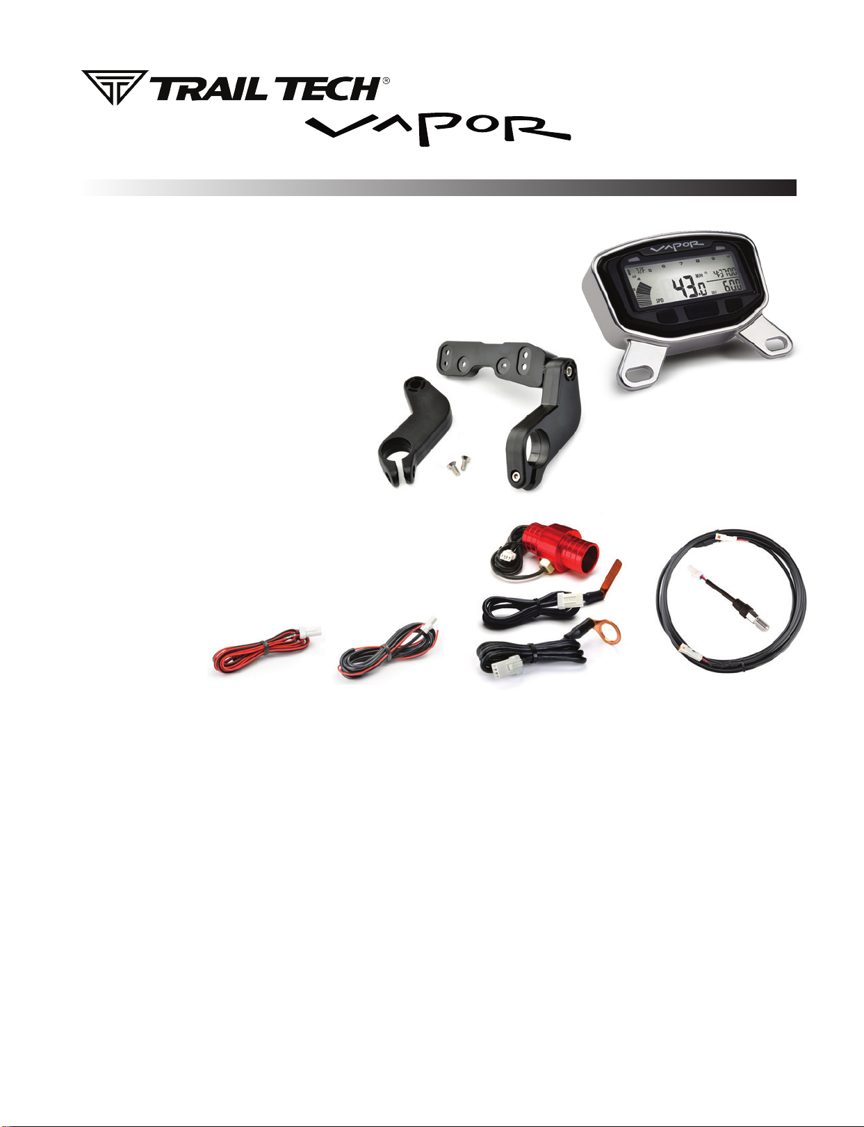
Aluminum
Protector Mount
(optional)
Temperature
Sensor (varies)
Power Wire Tach Ignition
Sensor Wheel Speed
Sensor (varies)
Included
Handlebar
Mount
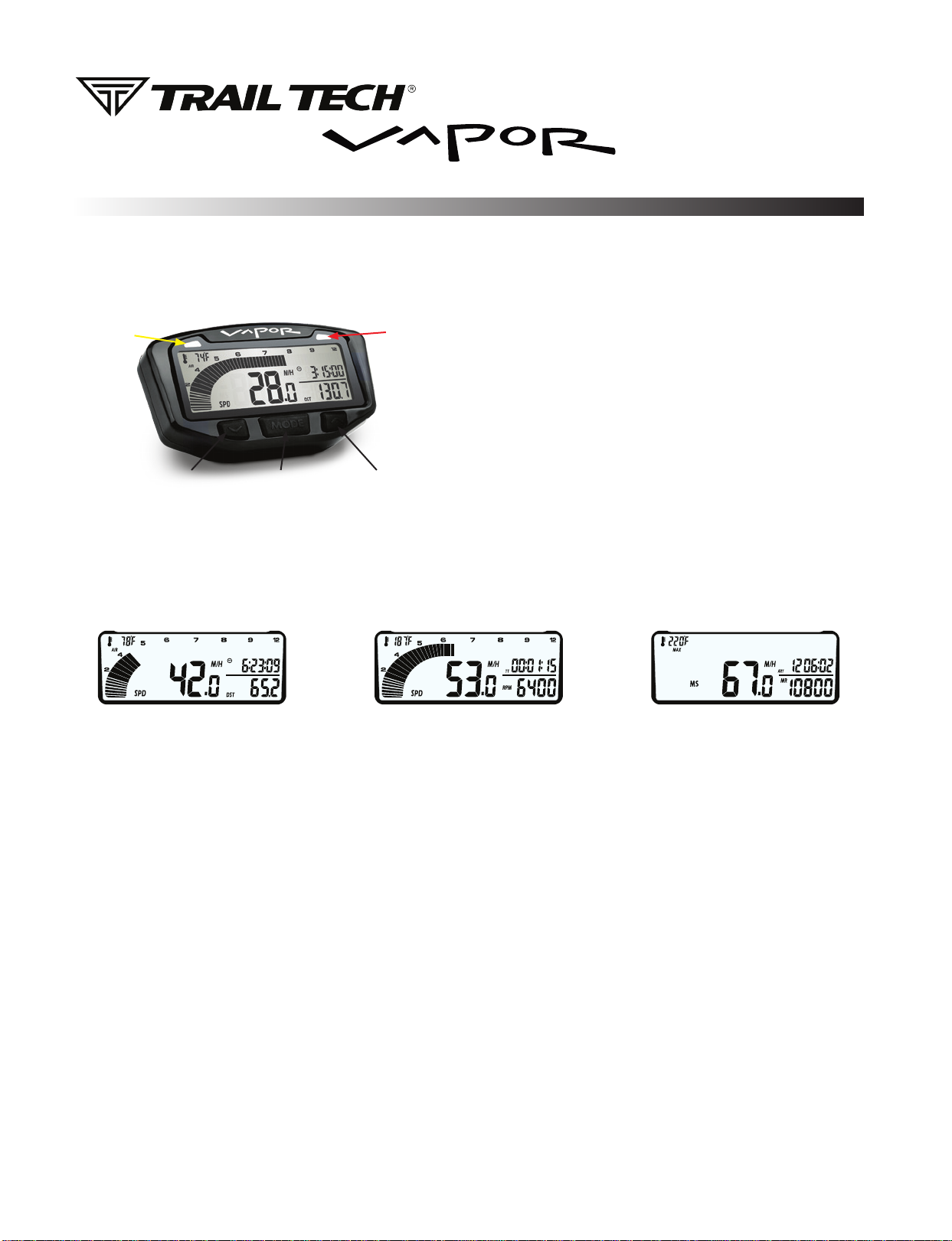
5. INDICATOR LIGHTS:
6. SLEEP MODE:
Vapor has two colored LED lights at the top. They are activated when tach or temperature goes above the thresholds to warn you about
potential problems with your vehicle. The left LED is yellow, the right LED is red. When the tach is over the rev limit the LED will flash, if the
temperature is high then the LED will turn on solid. Set custom thresholds in the DATA SETTING MODE. Set the thresholds to 0 to turn them off.
If Vapor sees no activity (either wheel movement or a button press) for 5 minutes, it will enter sleep mode and only display the clock. Sleep
mode will end when any activity is noticed. During sleep mode Vapor is using the internal battery and will not draw down vehicle power.
QUICK-START
9. DATA SETTING MODE :
HOLD DOWN ALL 3 BUTTONS to enter data setting mode.
Adjust one setting at a time, then move on to the next one.
<LEFT> = Scroll value.
<MODE> = Move to next data setting screen.
<RIGHT> = Move to next digit in data setting mode.
7. BUTTONS:
8. SCREENS:
Vapor has three screens. Press MODE to toggle between them.
Vapor has 3 screens, press MODE to cycle between screens. Press RIGHT on screen 2 to toggle Ride Time/Stop Watch. Press RIGHT on
screen 3 to toggle Odometer/Accumulated Ride Time. Hold all three buttons to enter data setting mode.
RESET TRIP DATA:
<LEFT> + <MODE> = HOLD TO RESET VALUES FOR:
Max Speed, Distance, Ride Time, Stop Watch, Max Engine
Temperature, and Max RPM.
ORDER OF SETUP MODE:
1. Speed and Distance Format
2. Wheel Size
3. Time Format
4. Time of Day
5. PPR Pulses per Revolution
6. PPR Pulse Change
7. PPR Level 2
8. Temperature Unit of Measure
9. Temperature Indicator
10. Temperature Indicator Danger
11. RPM Shift Indicator
12. RPM Shift Indicator Danger
M/H or KM/H
See MEASURE WHEEL SIZE section
12H or 24H
12:00:00
0.5, 1, or 2
RPM when PPR changes
0.5, 1, or 2
°F or °C
Yellow Indicator
Red Indicator
Yellow Indicator
Red Indicator
SCREEN 1
• Time of Day
• Ambient Air Temperature
• RPM Bar Graph
• Speed (SPD)
• Distance (DST)
SCREEN 2
• Engine Temperature
• RPM Bar Graph
• Stop Watch (TT)
• Ride Time (RT)
• Speed (SPD)
• Revolutions per Minute (RPM)
SCREEN 3
• Maximum Temperature (MAX)
• Accumulated Ride Time (ART)
• Odometer (ODO)
• Maximum Speed (MS)
• Maximum RPM (MR)
LEFT BUTTON
Start stop watch MODE BUTTON
Switch screens
Hold to edit trip distance
RIGHT BUTTON
Toggle between
screen features
YELLOW
LED RED
LED
POWER AND TACH SENSORS
INSTALLS
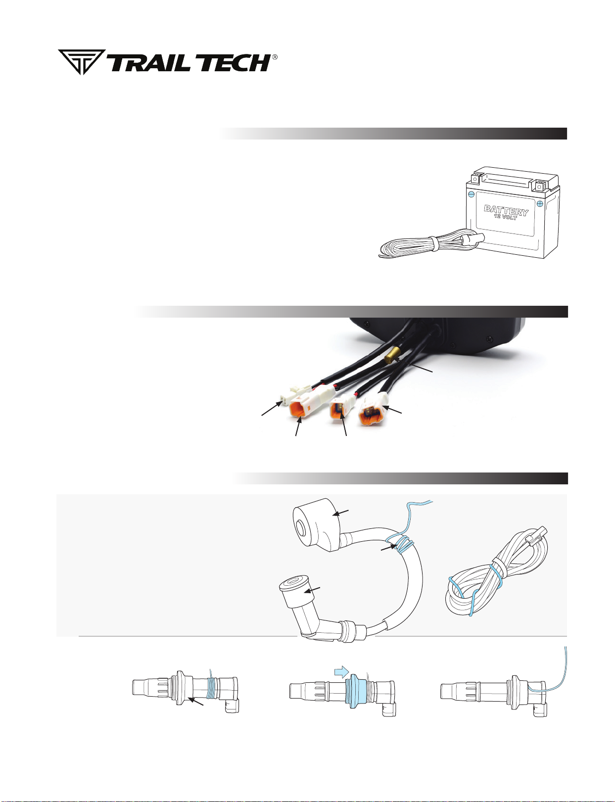
POWER CONNECTION:
FOR USE ON 6-400 VDC/VAC SYSTEMS ONLY!
Vapor will operate in the range of 6-400 VAC/VDC, but will not draw enough power to
drain a vehicle battery. Use a volt meter to confirm 6-400 VDC/VAC. Vapor is polarity
independent, so it cannot be installed backwards.
Fuse: Introducing a fuse into the circuit before electronics is always a good idea.
Use a 1 amp fuse with Vapor (not provided).
System Tap: It is possible to tap into the vehicle electrical system anywhere in the circuit.
Possible points are at the lights, ignition, or CDI. When tapping into the electrical system,
connect to a circuit protected by fuse.
MX Bikes: Most do, but some motocross bikes do not have 12 volt power. If there is no
vehicle battery or capacitor, connect power wire to ignition power leads from stator.
Use caution, as this is a high voltage option.
Power Wire
SENSORS:
Step 1:
Pull water-seal
down. Wrap
ignition sensor
around spark
plug.
Step 2:
Replace
water-seal.
Step 3:
Reinstall
spark plug
into motor.
OPTION 2:
If the coil is attached to the spark plug, then wrap the sensor like this:
Water
Seal
TACH IGNITION SENSOR:
Ignition
Sensor
Ignition
Sensor
Wrap
Coil
Spark Plug
The ignition sensor enables tachometer readings and the
animated bar graph of Vapor.
OPTION 1: (Preferred option for most vehicles.)
Capacitive coupling to spark plug wire:
1.
If required, you may shorten the length of the ignition
sensor. Be very careful when stripping back the black
casing to avoid damaging the inner red wire.
To install ignition sensor wire, wrap the
red part of the sensor wire around the
coil wire 5 times.
Ignition Sensor
Ambient Temperature Sensor
Engine Temperature Sensor
Wheel Sensor
Vehicle Power
The Vapor sensors plug securely into
Vapor using waterproof connectors.
They are different sizes (you cannot plug a
sensor into the wrong connector.)
TEMPERATURE SENSOR
INSTALLS
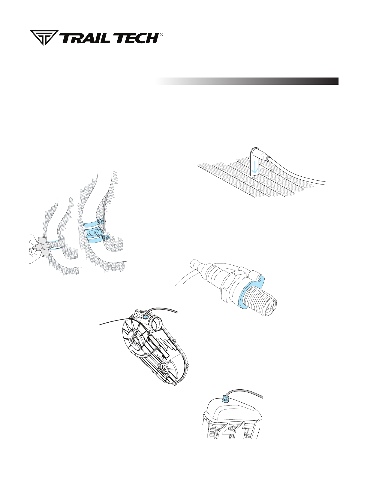
TEMPERATURE SENSORS:
Most Vapor kits contain a model-specific temperature sensor. Installing the temperature sensor enables
temperature readouts on Vapor. Alternative sensors are available.
Vehicles cooled with water use sensors to measure the fluid temperature, while air-cooled machines take
the cylinder head’s temperature at the spark plug. The radiator fin sensor is the easiest installation for
water cooled applications.
CVT Sensor Install:
(Continuously Variable Transmission)
200ºF+ Warning: CVT Belt wear occurs
more rapidly at high temperatures.
Let the belt cool down to increase lifespan.
Drill 13/64” (5mm) hole in
hard plastic CVT exhaust.
Thread sensor into hole.
The sensor threads are M6x10.
Use high temp RTV (silicone
gasket sealer) to seal case cover.
Not included in kit.
1.
2.
3.
Radiator Hose
Sensor Installation:
Drain uid.
Measure inner diameter
of hose before cutting.
Mark hose.
Cut hose.
Slide on hose clamps.
Install sensor & tighten
hose clamps.
1.
2.
3.
4.
5.
6.
Mark
& Cut
Tighten
CHT Cylinder Head
Spark Plug
Sensor Installation:
Remove crush
washer from
spark plug.
Replace with
temperature
sensor.
Re-install
spark plug.
1.
2.
3.
Sensor replaces
crush washer
Radiator Fin
Sensor Installation:
Conrm correct size.
Apply thermal grease to
maximize heat transfer.
Carefully press sensor
between radiator ns.
1.
2.
3.
If the in sensor is too large,
le it to size rather than
forcing it into the radiator.
Screw
Sensor Installation:
1.
2.
Remove radiator pressure
relief bolt.
Replace with temperature
sensor.
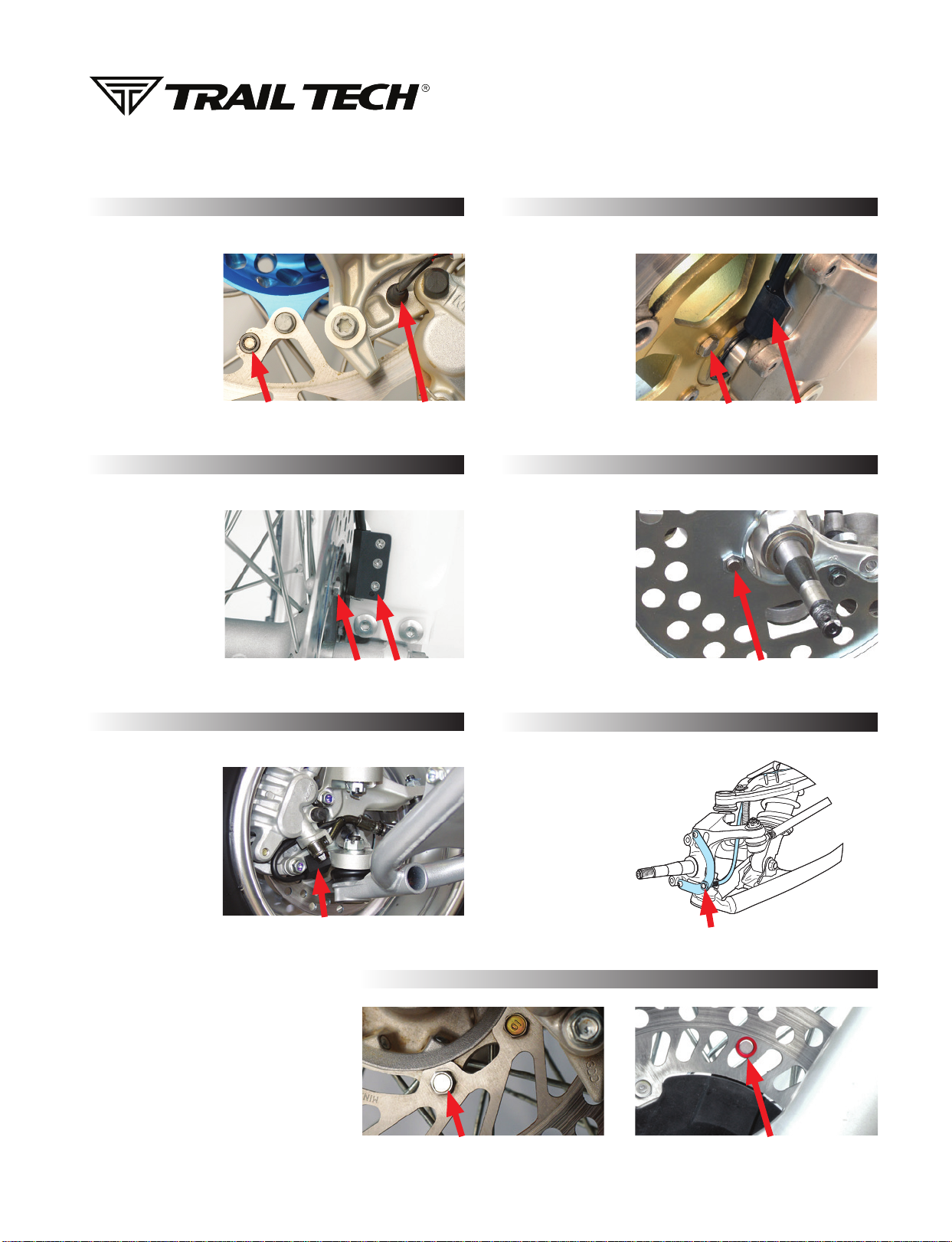
WHEEL SENSORS
INSTALLS
Some ATVs require
mounting the wheel
sensor directly to the
brake caliper.
Drill a 1/8” hole
through the caliper
mount, then use the
self-tapping screw to
secure the sensor.
BRAKE CALIPER WHEEL SENSOR
Brake Caliper
Wheel Sensor
If the fork is close to
the brake rotor, then
the VHB fork sensor
can be used. Peel
and stick the sensor
to the fork.
Try to have the tip of
the sensor about 1/2
inch away from the
magnet in the rotor. Rotor Bolt Magnet
Some kits include
a metal C-bracket
to help mount the
sensor, as shown.
Use the jam nuts to
secure the sensor to
the C-bracket. Use
loctite rather than
over-tightening the
jam nuts.
C-BRACKET WHEEL SENSOR
C-Bracket
Wheel Sensor
Trail Tech wheel
sensors work with the
KTM and Husqvarna
OEM install location.
Screw the wheel
sensor into the OEM
caliper position. Insert
the black magnet into
the pre-drilled hole in
the rotor and secure
with the retainer clip.
KTM WHEEL SENSOR
KTM Magnetic
Retainer KTM OEM Wheel
Sensor Position
If there are fork
guards next to the
brake rotor, then the
fork guard wheel
sensor can be
installed as shown.
Try to have the tip of
the sensor about 1/2
inch away from the
magnet in the rotor. Rotor Bolt Magnet Rotor Shield
Wheel Sensor
For UTVs and quads
with a rotor shield,
position the sensor
there.
Drill a 3/8” hole and
use the jam nuts to
secure the sensor to
the rotor shield. Use
loctite rather than
over-tightening the
jam nuts.
ROTOR SHIELD WHEEL SENSOR
MAGNET INSTALLATION:
Install a magnet on the brake rotor to trigger
the speed sensor each wheel rotation.
Remove one of the stock rotor bolts and
install the magnetic rotor bolt as shown, do
not overtighten past 10 ft-lb of torque. If the
magnetic bolt will not work, the kit includes a
spare magnet that can be installed into one
of the rotor spaces. Use the included retainer
clip or epoxy such as JB Weld to secure. Magnetic Retainer or Spare MagnetMagnetic Rotor Bolt
CONVENTIONAL FORK SENSOR
Conventional Fork
VHB Wheel Sensor
INVERTED FORK WHEEL SENSOR
Inverted Fork
Wheel Sensor
X = 2131
X = 5 x 2110
4.95
(new wheel size) (actual miles) x (current wheel size)
(current miles)
=
X = 10550
4.95
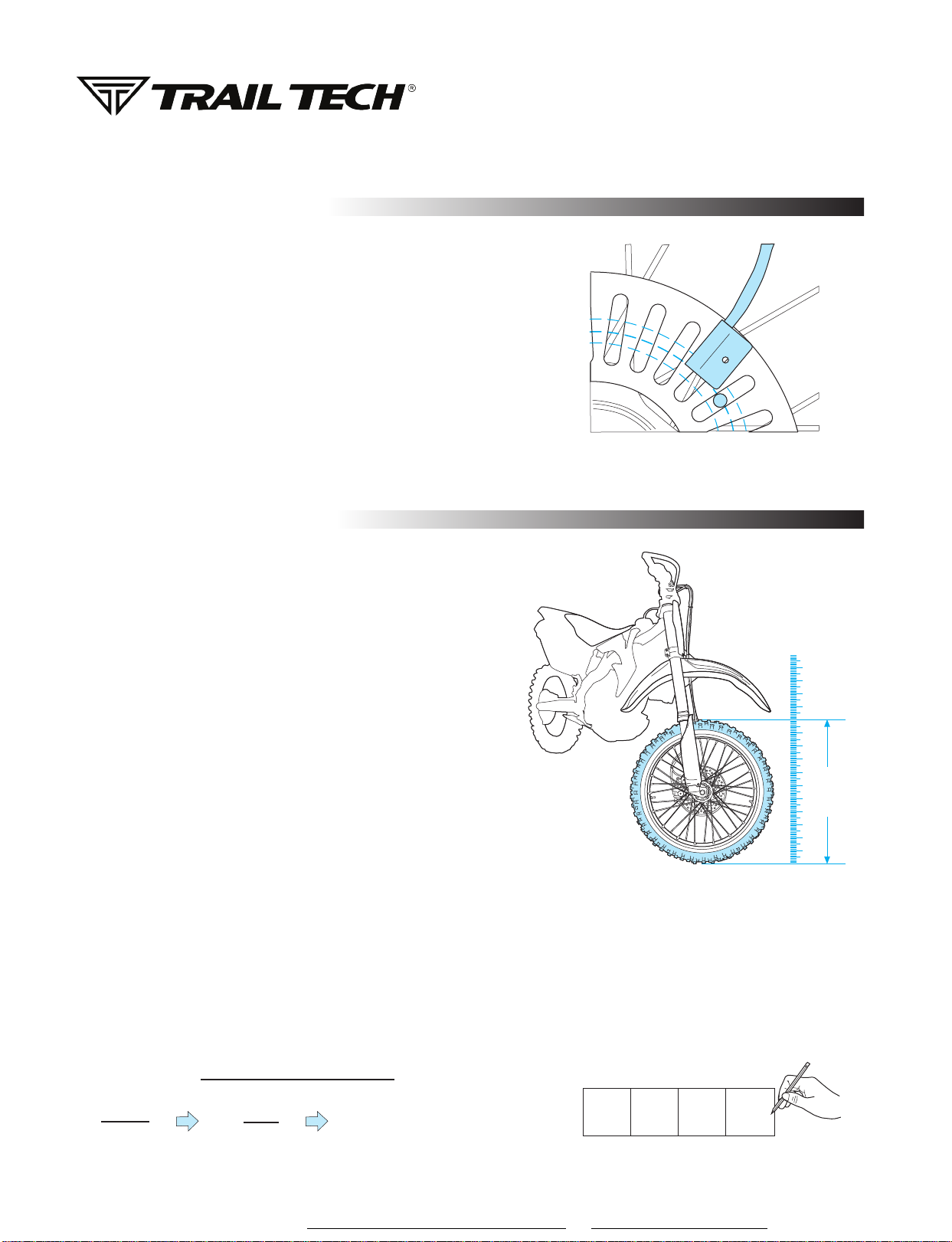
MEASURE WHEEL SIZE:
WHEEL SENSOR TEST:
Test for correct sensor/magnet placement before permanently mounting.
1. Set the vehicle on a stand so that the front (left) wheel spins easily.
2. Plug the wheel sensor cable into the computer.
3. Install the magnetic bolt.
4. Hold the sensor in place on the caliper mount by hand. While someone
watches the computer, roll the wheel. If the computer does not register,
move the magnet or sensor and try again. There should be 1/2” or less
gap between the sensor and magnet.
Do not mount so that the magnet passes the middle section of the
sensor. Either the sensor will not register at all; or the sensor will
register twice, causing a “double trigger” effect (computer displays
twice the true speed.) If a double-trigger is unavoidable, divide the wheel
size setting in the computer by 2 to correct the problem.
Magnet Rotation Path
Knowing your exact wheel size it critical for the wheel sensor to calculate
correct speed and distance data.
When comparing calibration to GPS data, use a long straight section of road
with no tight corners or small vertical movements.
On a at surface, mark the tire sidewall and the ground with a marking pen. Roll the
wheel until the mark on the tire completes one revolution and is back on the ground. Mark
the ground at this location. Measure the distance between the marks on the ground in
millimeters (multiply inches by 25.4 to convert to mm). Use this number for your wheel size.
For accuracy, the rider’s weight should be on the bike when making the measurement.
Method 2: Rolling
Find the circumference of front wheel by measuring its diameter in millimeters.
Multiply the Wheel Diameter by 3.14. The result is your wheel size.
Method 1: Ruler
Enter the number you calculate from one of
the above formulas into setup mode.
Method 3: Distance Measurement
This is the most accurate method.
1. Set the wheel size to 2110mm (motorcycle) or 1675 (ATV).
2. Find a length of road where the distance is known.
3. Ride the distance, noting how far the computer reads (i.e. the road
is known to be 5 miles and the computer shows 4.95 miles.)
4. Use the numbers to solve for X in the following equation:
Wheel Size =
Wheel Diameter(mm)
x3.14
Diameter
x3.14
Wheel Size:
Motorcycle:
ATV: 2110 mm
1675 mm
Generic/Average Sizes:
WHEEL SENSORS
SETUP
Learn more about other motorcycle dashboard & gauges by Trail Tech on our website.
Other manuals for Vapor
2
Table of contents
Other Trail Tech Motorcycle Accessories manuals


