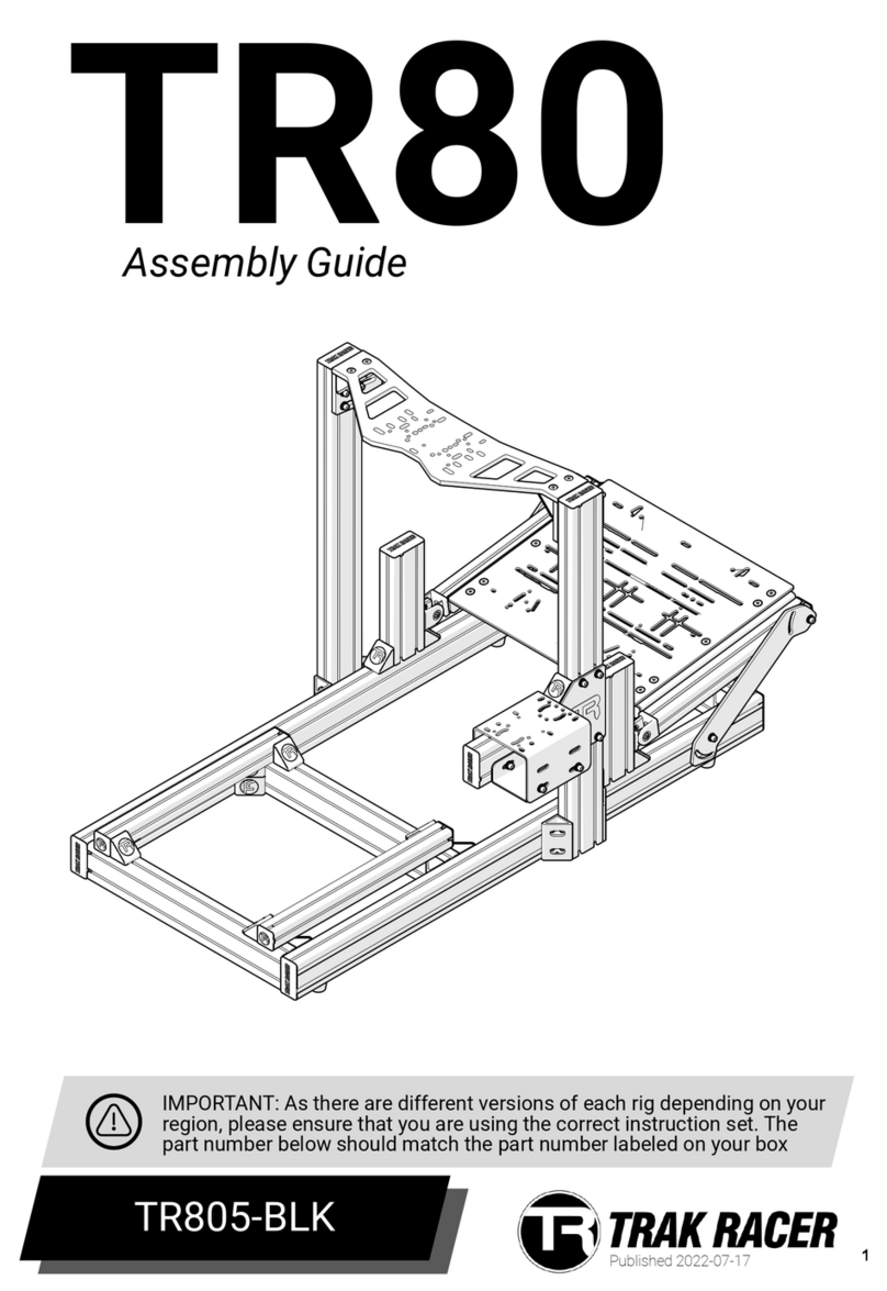
TRAK RACER TR120 User manual

1
Published 2023‑08‑23
TR120
Assembly Guide
TR120-BLK
IMPORTANT: As there are different versions of each rig depending on your
region, please ensure that you are using the correct instruction set. The
part number below should match the part number labeled on your box
tooltip

3 Symbol Legend
4 Part list
5 Assembly Notes
9 TR120-BLK Assembly Instructions
16 Stabilizing Feet Option
18 Seat Slider Option
20 Recliner seat installation
24 GT/Rally seat installation
26 Pedal Option 1
29 Pedal Option 2
32 Pedal Option 3
35 Pedal Option 4
39 Wheel Mount Option 1
42 Wheel Mount Option 2
45 Wheel Mount Option 3
48 Wheel Mount Option 4
51 Wheel Mount Option 5
54 Shifter Option 1
56 Shifter Option 2
2
TABLE OF CONTENTS

3
Two people needed
Tighten hardware
Leave hardware loose for adjustment
Make Adjustment
Break tab off Corner bracket CB1
Safety glasses needed
Attention / Priority
Reserve for following step
Mirrored Components (Same on both sides)
IMPORTANT: As there are different versions of each rig depending on your
region, please ensure that you are using the correct instruction set. The
part number below should match the part number labeled on your box
IMPORTANT: Due to the nature of cut aluminium prole, some metal
shavings may still be present after our extensive QA cleaning process. We
recommend that boxes and packaging is opened on a hard oor.
NOTE: Some screws and washers are pre-installed. These will be part of
the parts list and will need to be loosened and reattached according to
the instructions.

IMPORTANT: As there are different versions of each rig depending on your
region, please ensure that you are using the correct instruction set. The
part number below should match the part number labeled on your box
4
If you have any issues, please contact us at support@trakracer.com
Part # Description QTY Check
BOX #: TR120-BLK-PART1
PS-780-R Prole strip, 780mm Red 2
PS-500-R Prole strip, 500mm Red 2
PS-460-R Prole strip, 460mm Red 2
AL-120-780 Aluminum Prole, 40x120x780mm 2
AT-120-780 Aluminum Prole (Threaded), 40x120x780mm 2
BOX #: TR120-BLK-PART2
CC-01 Cable Management clips 10
BC-40 Bracket, Corner with Cap, 40x40 8
BA-120-BLK Bracket, Anodized corner, 40x120, Black 6
EC-120 End Cap, 40x120 4
EC-40 End Cap, 40x40 4
FR-01 Feet, Rubber 4
LP-120 Logo Plate, TR120 1
NS-M8 T-Nut (Spring), M8 24
NS-M8 T-Nut (Spring), M8 16
NS-M6 T-Nut (Spring), M6 8
AL-120-580 Aluminum Prole, 40x120x580mm 1
AT-120-500 Aluminum Prole (Threaded), 40x120x500mm 2
AT-120-580 Aluminum Prole (Threaded), 40x120x580mm 1
AL-40-460 Aluminum Prole, 40x40x460mm 2
SH-M8-16 Screw (Hex), M8x16 24
SB-M6-12 Screw (Button), M6x12 4
SH-M8-20 Screw (Hex), M8x20 12
SH-M8-20 Screw (Hex), M8x20 16
SH-M6-20 Screw (Hex), M6x20 4
SH-M8-35 Screw (Hex), M8x30 12
SS-01 Seat Slider 1
TK-M8 Tool Kit, M8 1
BCH-120 Chicane Connector, 120mm 2
WF-M8 Washer (Flat), M8 20
WL-M8 Washer (Lock), M8 28
tooltip
TR120-BLK-PART1
TR120-BLK-PART2
TR120-BLK PARTS LIST
*NOTE: Extra hardware may be included as spare parts
tooltip
INCLUDED TOOLS
6mm Ball End Hex Key
13mm Spanner

5
1
NOTE
BACK SIDE
FRONTSIDE
INSIDE
TOP SIDE
OUTSIDE
SHIFTER SIDE
a
a
a
a
a
a
INSTALLATAION ORDER FOR SCREWS HOW TO MEASURE SCREWS
①SCREW ②LOCK WASHER
(IF APPLICABLE)
③WASHER
FLAT SCREW
HEX SCREW
BUTTON SCREW

6
NOTE
The handle screws (S7 & S27) are ratcheted to
allow for tightening and loosening when space
for rotation is limited. Simply pull the handle out
and turn handle into position and push handle
back in to engage thread.

7
NOTE
tooltip
tooltip
tooltip
tooltip
If T-Nuts are skipped, and
the ends are no longer
accessible, they can be
inserted by “rocking” them
in from the outer face as
shown.
Use the provided allen key
to push the T-Nut into
position and place the hole
to slide into position.
It is strongly advised that
spring T-Nuts are inserted
by sliding from the ends of
profiles. Please take careful
note of each step of all T-nuts
as some are to be installed in
anticipation of future steps.
NS-M8 & NS-M6

8
NOTE BC-40

tooltip
tooltip
9
If using stabilizing
feet, go to P.18
Insert 2pcs of NS-M8 into
TOP of AT-120-580 (for STEP 5)
SB-M6-12 x4
1
2
LP-120 x4
M6x20mm
SH-M6-20 x2
AT-120-500 x2 NS-M6 x2
AT-120-580 x1 NS-M8 x2 NS-M6 x4
FR-01 x2

tooltip
tooltip
10
4
3
Insert 2pcs of NS-M8 into
TOP SIDE of AL-120-580
(for STEP 5)
BA-120-BLK x2
M8x20mm
SH-M8-20 x12
AL-120-580 x1 NS-M8 x10

tooltip
tooltip
344mm
13.5"
tooltip
SH-M8-20 x8
M8x20mm
WL-M8 x8 WF-M8 x8 BC-40 x4
11
5
6
380mm
15"
AL-40-460 x2 SH-M8-20 x8
M8x20mm
WL-M8 x8 WF-M8 x8 BC-40 x4 NS-M8 x4

M8x35mm
SH-M8-35 x6 BCH-120 x2
12
7
8
If using stabilizing
feet, go to P.18
M6x20mm
SH-M6-20 x2
AT-120-780 x2 NS-M6 x2 FR-01 x2
WL-M8 x6

WL-M8 x6
tooltip
13
9
10
M8x35mm
SH-M8-35 x6
AL-120-780 x2
M8x16mm
SH-M8-16 x24 NS-M8 x24 BA-120-BLK x4

tooltip
14
11
Note: End caps should be
installed after all
accessories are mounted
EC-40 x4
BC-40 x8 EC-120 x4

15
tooltip
12
tooltip
PS-780-R x2 PS-500-R x2 PS-460-R x2

16
Published 2023‑08‑23
Seat Slider
Assembly
TR80-SLIDER
Part # Description QTY Check
BOX #: TR120-BLK-PART2
SS-01 Seat Slider 1
SH-M8-16 Screw (Hex), M8x16 4
NL-M8 Nut (Locking), M8 4
WF-M8 Washer (Flat), M8 4
WL-M8 Washer (Lock), M8 4

tooltip
tooltip
17
1
SS-01 x1 NS-M8 x4
M8x16mm
SH-M8-16 x4 WL-M8 x4

18
Published 2023‑08‑23
Stabilizing Feet
Option
TR80-TR160FEET
tooltip
Part # Description QTY Check
BOX #: TR80-TR160FEET
SH-M8-25 Screw (Hex), M8x25 8
WF-M8 Washer (Flat), M8 8
WL-M8 Washer (Lock), M8 8
NS-M8 T-Nut (Spring), M8 8
BF-01 Bracket, Feet Adjustable 4
FA-01 Feet, Adjustable 4
*NOTE: Extra hardware may be included as spare parts

tooltip
tooltip
19
FA-01 x4
BF-01 x4
1
2
NS-M8 x8 SH-M8-25 x8
M8x25mm
WL-M8 x8 WF-M8 x8

20
SA-06/SA-07/SA-08
Recliner Seat
Assembly
This manual suits for next models
1
Table of contents
Other TRAK RACER Switch manuals