Trak-Star RailBoss User manual

OPERATOR’S MANUAL
PORTABLE 4-STROKE RAIL DRILL --- MANUAL FEED
70 LB. A.S.C.E. TO 155 LB. P.S.
Serial #: _______________________ Date: ______________

2
TRAK-STAR
®
Portable Gas Rail Drill
Model RB28
Welcome to Trak-Star
Congratulations on your purchase of the Trak-Star Portable Gas Rail Drill. Your model is designed to produce
superior holes quickly and effi ciently. Through constant innovation and development, Trak-Star is committed
to provide you with hole-producing tools and products that lead the industrial world.
Before attempting to operate your new Rail Drill, please read all instructions fi rst. These include the Operators
Manual and warning Label on unit itself. With proper use, care, and maintenance, your model will provide you
with years of effective hole drilling performance. Once again, thank you for selecting our product and welcome
to Trak-Star.
1. Open shipping carton and remove the literature and
hardware packages.
2. Read and Follow All Instructions before attempting
to operate your new Rail Drill.
3. Complete and mail the Product Registration Card
NOW
. It is important that Hougen Manufacturing, Inc.,
have a record of product ownership.
4. Open all hardware packages and check contents.
10565 Hex wrench 1/8”
13013 Hex wrench 5/32”
10570 (2) Knobs
03522 Shaft
03635 Pilot
27019 Feed Handle Assy
01592 Coolant Bottle
27091 Oil
5. Lift Rail Drill out of shipping carton using center
carrying handle and rear support handle.
6. Attach the large feed handle onto the drill using the
enclosed 5/32” hex wrench.
7. Attach Clamp Handle using the enclosed 1/8”
hex wrench.
8. ADD 8 OZ OF OIL TO THE MOTOR.
9. Your new Rail Drill was factory adjusted prior to
shipping. Check to make sure that all screws, motor
hold-down screws, drill housing and shoe mounting
screws are snug and have not vibrated loose in
transit.
10. Hookup Coolant Bottle / Hose Assembly (01592).
Connect the quick-disconnect hose fi tting to the Rail
Drill.
11. Reread Safety Warnings listed in this Operator’s
Manual and on the drill unit to avoid injury. Follow
operating procedures.
Your new Rail Drill is equipped with a twist arbor bore to
accept TRAK-STAR Twister Bits. Order cutters separately.
Install pilot thru cutter before attaching cutter to arbor.
Unpacking Your New Rail Drill
Index
Welcome to TRAK-STAR 2
Unpacking Your New Rail Drill 2
Important Safety Instructions 3
Model features 4
Installing / Replacing Cutter 5
Drill and Pressurized Coolant System 6
Clamping Procedures 7
Positioning of Hole Location Template 8
Important Notice 9
Operating Instructions 9
Section Page
Maintenance - - Engine/Drill 10
Clamp Exploded view & Parts 11
RB28 Exploded View 12
Parts List 13
Engine Parts Diagram and parts 14
Rail and Shoe Data 15
Commercial / Industrial Warranty 16
- Factory Authorized Service Centers
Section Page
OIL MUST BE ADDED TO THE
ENGINE BEFORE STARTING.
FAILURE TO DO SO WILL RESULT IN
ENGINE DAMAGE WHICH IS NOT
COVERED UNDER WARRANTY.
WARNING!

3
• Quill and cutter should never be used as a
handhold.
• Keep hands and clothing away from all
moving parts.
• Do not use Twister Bits where ejected slug
might cause injury (slug ejected at end of cut).
• Be sure that all safety devices are properly
adjusted and in use. Also, adhere to all
operating instructions.
• Do not attach Rail Drill to live 3rd rail track.
18.
Non-Conforming Cutting Tools
The TRAK-STAR Model RB28 is designed
to use TRAK-STAR Twister Bits only. The use
of drilling tools having different shank styles is
not recommended as they may not tighten
securely in the TRAK-STAR arbor with risk of
accident or injury.
19.
Save These Instructions
20.
Read all instructions concerning the motor
in your HONDA Engine Operator’s manual.
1.
Read All Instructions
2.
Keep Work area clean
Cluttered area and benches invite injuries. Keep dirt
and chips from under Twister Bit area and drill shoe.
3.
Consider Work Area Environment
.
Keep work area well lit.
4.
Keep Children Away
Do not let visitors contact tool.
5.
Store Idle Tools
When not in use, tools should be stored in a dry, and
a high or locked-up place -- out of reach of children.
6.
Do Not Force Tool
It will do the job better and faster at the rate for which
it was intended.
7.
Use Right Tool
Do not force small tool or attachment to do the job
of a heavy duty tool.
Do not use tool for purpose not intended -- for example
do not use a circular saw for cutting tree limbs or logs.
8.
Dress Properly
Do not wear loose clothing or jewelry. They might
entangle with spinning chips or get caught in moving
parts. Rubber gloves and nonskid footwear are
recommended when working outdoors. Wear sturdy
leather gloves when working indoors.
14.
Remove Adjusting Keys and Wrenches
Form a habit of checking to see that keys and
wrenches are removed from tool before Starting drill
unit.
15
Stay Alert
Watch what you are doing. Use common sense.
Do Not operate tool when you are tired.
9.
Always Wear Safety Glasses or Goggles.
10.
Do Not Overreach
Keep proper footing and balance at all time.
11.
Secure Work
Clamp work securely using appropriate shoe size and
shape.
Tighten Clamp by using two hands with handle
placed in central position and tighten securely.
12.
Maintain Tools With Care
Keep tools sharp and clean for better and safer
performance.
Do not use dull or broken Twister cutters. Follow
instructions for lubricating and changing accessories.
Inspect gas line periodically and, if damaged, have
repaired by authorized service facility.
Keep handles dry, clean, and free from oil and
grease.
13.
Disconnect Tools
Disconnect spark plug wire from spark plug when not
in use, before servicing, and when changing
Twister Bits or accessories.
16.
Check Damaged Parts
Before further use of drill, a part that is dam-
aged should be carefully checked to determine
that it will operate properly and perform its
intended function.
Check for alignment of moving parts, binding of
moving parts, breakage of parts, mounting, and
any other conditions that may affect its opera-
tion.
A part that is damaged should be properly
repaired or replaced by an authorized service
center unless otherwise indicated elsewhere in
this instruction manual.
(See last page for authorized Service Centers)
17.
Additional Safety Precautions
Important Safety Instructions

4
PLEASE READ THE HONDA ENGINE OPERATOR’S
MANUAL. INSTRUCTIONS ON THE OPERATION,
SAFETY, AND MAINTENANCE PROCEDURES ARE
CONTAINED IN A SEPARATE MANUAL.
IMPORTANT:
Before starting the machine, it is impera-
tive that the operator know and understand instructions
for safe operation.
Add engine oil to motor and use regular
unleaded gasoline only.
Ignition switch located on engine---stops motor, spindle, and cutter
rotation. See diagram at left.
“ON” / “OFF” Switch
“ON” / “OFF” Switch
The World’s Most Reliable
4-Stroke Rail Drill
Honda Engine Instructions
Honda Engine Instructions
Honda Engine Instructions
GAS MUST BE SHUT OFF BEFORE
TRANSPORTING DRILL.
5
TRAK-STAR Twister Disposable Rail Cutters
Made from Premium H.S.S.
• Gold Coating for All Around Drilling
• Black Coating for Improved Performance
in New Harder Rail.
TRAK-STAR Rail Drills are designed to use Twister
Bits, and to achieve maximum effi ciency from your
unit, we recommend that no substitutes be used.
** Twister Bits are economical and disposable
--- there is no need to resharpen --- however it is
possible. Tools can be sharpened 2 to 3 times.
Send cutters to Trak-Star to the attention of the
Resharpening Department.
** Twister Rail Bits have been shown to drill holes
in rails up to 4X faster than twist drills or spade
drills, and they produce clean, round, burr-free
holes without the need to chamfer.
** Multiple cutting edge design, along with proper
coolant fl ow, produces a cool cut raising the rail
temperature in the hole no more than 35°F above
ambient temperature. This prevents work harden-
ing, stress cracking, service failures, and repeated
repairs.
Cutter
Size,
inches
Decimal
Equivalent
Gold -
TiN Coated
Part Number
Black -
TiAlN Coated
Part Number
7/8 .08750 15228 15328
15/16 .09375 15230 15330
1 1.0000 15232 15332
1-1/16 1.0625 15234 15334
1-1/8 1.1250 15236 15336
1-3/16 1.1875 15238 15338
1-1/4 1.2500 15240 15340
1-5/16 1.3125 15242 15342
1-3/8 1.3750 15244 15344
1-7/16 1.4375 15246 15346
1-1/2 1.5000 15248 15348
1-11/16 1.6875 15254 15354
Pilot for Twister Bits 03635
Installing / Replacing Twister
TM
Bit
1. Be sure engine is stopped and turned off. Turn off
coolant at shut-off. The spring seat system located
within arbor was not designed to be 100% leak proof.
2. Position arbor so the cutter area is easily accessible.
Do not depress pilot pin during procedure to release
seal. Doing so will result in releasing pressurized
contents of arbor cavity and coolant loss. Some loss,
however, is normal due to cavity between cutter shank
and spring seat.
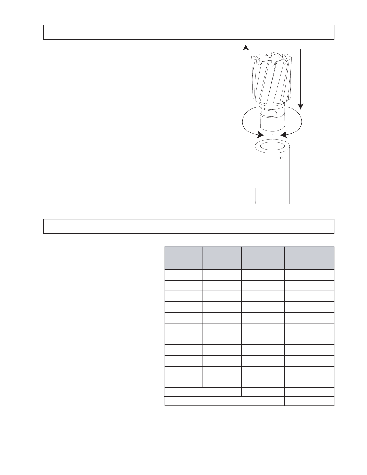
3. Insert pilot in shank end of Twister Bit.
4. Insert the Twister Bit until long fl at on cutter shank is
aligned with roll pin inside arbor. Twist cutter clockwise
(do not depress pilot in case of cutter replacement for
reason noted in #2). The cutter is automatically held
into place.
Insert Cutter
into Arbor
Twist
OFF ON
Twist

Drill & Pressurized Coolant System
1. Install correct shoes for rail type being drilled.
2. Install correct size Twister Bit with pilot and secure
to drill arbor. See Cutter Installation procedure.
3. Fill coolant bottle with TRAK-STAR cutting fl uid ( a water
3. Fill coolant bottle with TRAK-STAR cutting fl uid ( a water 3. Fill coolant bottle with TRAK-STAR cutting fl uid ( a water
soluble and biodegradable product) Conventional fi ll
access is achieved by removing pump handle.
Caution: Contents under pressure. Partially open
to slowly release pressure before removing.
4. Attach coolant bottle quick connect hose fi tting to drill
on the backside of drill under motor.
5. Pressurize coolant bottle (approximately 20 pumps)
6. Open coolant shut off valve.
7. Depress pilot pin approximately 1/4” and watch for
coolant fl ow from the end of the cutter. NOTE - Coolant
is under pressure -- stay out of path of spray. If coolant
does not fl ow, rotate valve further to open or unclog
coolant system.
6
RotaMagic™ Concentrate Cutting Fluid
A good fl ow of cutting fl uid to the tool is important. It cools
and lubricates the cutting edge, helps evacuate the chips,
keeps the slug from expanding, and helps eject the slug.
Various mineral and sulphur base oils are quite popular,
however, water base solutions have better cooling qualities.
Listed is our own recommended Concentrated Cutting Fluid
for Twister Bits and similar cutting tools. It is a water soluble,
biodegradable product. This cutting fl uid contains no ingredi-
ents that are on the U.S. Government Hazardous Materials
List. It is a super concentrated form that will require a 10:1
mixture of water.
RotaMagic™ Concentrate Cutting Fluid
Coolant Quick Connect Hose and Nipple
rebmuNredrO noitpircseDeziS
4-24711 **snollaG4
34711 +snollaG5
NISEMOC.ETARTNECNOCFOTNUOMADERUSAEM**
FOSNOLLAG44SEKAMDNASRENIATNOCNOLLAG1-4
DIULFGNITTUCELBASU
EKAMLLIW,LLUF,RENIATNOCNOLLAG-5NISEMOC+
DIULFGNITTUCELBASUFOSNOLLAG55
01569 On/Off Valve
05621 Quick Connect Fitting
01592 Coolant Bottle and Hose Assy
Coolant System Replacement Parts
Do Not Use Straight Water or Window
Washer Fluid. Damage to Drill Will Occur!
Only Use Trak-Star RotaMagic Coolant.

7
FIGURE A.
FIGURE B.
FIGURE C.
FIGURE D.
CLAMPING PROCEDURES
STEP #1:
WITH CLAMP IN OPEN POSITION,
REST UNIT ON RAIL BASE. BOTTOM
OF SHOES SHOULD CONTACT
TAPER ON RAIL BASE.
(SEE FIG. A)
** PERFORMANCE TIP: CLOSE
CLAMP UNTIL CLAMP PAD CON-
TACTS WEB OF RAIL PRIOR TO
STEP #2.
STEP #2:
RAISE REAR OF RAIL DRILL TO
LOCATE SHOES IN PROPER
POSITION.
(SEE FIGURE B)
STEP #3:
WHILE MAINTAINING CONTACT
BETWEEN SHOES AND RAIL,
TIGHTEN CLAMP.
(SEE FIG. C)
STEP #4:
WHEN UNIT IS FIRMLY CLAMPED,
CHECK FOR PROPER SHOE AND
PAD CONTACT ON BOTH SIDES
(SEE FIG. D)
WARNING: IMPROPER CLAMPING WILL CAUSE PREMATURE
CUTTER FAILURE
* When properly clamped to the rail there will be
a small gap between the top of the shoe and the rail.

Positioning of Optional Hole Location Template
Template is positioned on head of rail with tapered tip fl ush
with end of rail and side locking screws fastened to rail
head. Notches in template give precise location of hole
centerlines to be drilled.
The rail clamp assembly has a locating arm which rests
in the template notches. The locating arm is adjustable to
accommodate the full range of rail sizes.
To use the locating arm, raise the drill unit over the rail with
the template attached and gently rest drill down until shoes
make contact with the rail. Flip the arm to make contact
with the template. Slowly slide drill across the template
until the arm falls into notch.
The arm must contact the sides of the matching notch.
Following the Clamping Instructions, clamp unit onto rail.
When the hole is completed, raise the arm by fl ipping the
arm back toward the body of the drill. Before drilling next
hole remove chips around cutter. Then move the drill side-
ways, ensuring the arm is clear of the notch, and fl ip arm
down. Slide the drill sideways until arm falls in the next
notch, and repeat the procedure as necessary.
Note: The locating arm must be fl ipped back, resting
on the body of the drill before putting the drill unit on
the rail. Failure to do so can result in damage to the
hole locating arm system.
Hole location templates are offered as optional equipment.
Four of these templates are provided with established hole
spacings. The 40570 template is produced to customer
specifi ed hole spacing. See chart for the template to match
your application.
8
Template
Part No.Hole Spacing
40570 Customer Specified
40701 3-1/2" X 6" X 6"
40702 2-11/16" X 5-1/2" X 5-1/2"
40703 2-1/2" X 5" x 5"
40704 2-1/2" X 6-1/2" X 6-1/2"
40706 2- 23/32" x 5-1/2" x 5-1/2"
Locating Arm
Location Template
28-1/2"
"A"
"B"
"C"
Specify “A”, “B”, “C” when ordering custom template
Custom Template Spacing

Operating Instructions
NEVER RUN ENGINE INDOORS OR IN ENCLOSED,
POORLY VENTILATED AREAS. ENGINE EXHAUST
CONTAINS CARBON MONOXIDE, AN ODORLESS
AND DEADLY GAS.
KEEP HANDS, FEET, HAIR, AND LOOSE CLOTHING
AWAY FROM ANY MOVING PARTS ON ENGINE AND
EQUIPMENT.
WARNING - TEMPERATURE OF MUFFLER AND NEAR
BY AREAS MAY EXCEED 150°F (65°C). AVOID THESE
AREAS.
1. Make sure workpiece, cutter and shoe surfaces are
free of chips, etc.
2. Place locator template on rail head.
3. Align drill on locator with the Hole Location Template.
4. Clamp drill to rail and insure proper 10 point contact.
5. Turn on coolant (pump to pressurize system).
6. Move choke lever to “FULL CHOKE”. If restarting a
warm engine after a short shutdown, move choke lever
to “NO CHOKE”.
7. Turn motor on/off switch to “ON” position.
8. Move throttle to idle position.
9. Grasp starter handle and pull rope out, slowly, until it
meets resistance. Let rope rewind slowly. Then pull
rope with a rapid full arm stroke. Let rope return to
starter slowly.
10. Repeat step #9 until engine fi res.
11. Move throttle to run position.
12. Manually feed cutter very gently to start cutting.
13. Once all teeth are cutting aggressively, feed tool
through workpiece at an even rate. Do not over-
load unit to induce an arbor stalling situation. Certain
rail compositions workharden easily. Do not pause
during cut nor release feed pressure if changing hand
grip on feed handle. This will result in premature
cutter wear and drilling problems while in the cut.
14. Move feed handle to retract arbor and cutter. Slug
should eject from spring loaded pilot pin pressure.
15. Move throttle to idle position.
16. At the end of the cut, move ignition switch on engine
to “STOP” or “OFF” position.
17. Loosen clamp and remove drill to clean chips from
around cutter. Drill cycle is complete and you are
ready to go on to the next hole. Shutting off coolant
after use is suggested, if use is intermittent.
If Slug Has Not Fallen Free
, disconnect spark plug
wire from spark plug and shut off coolant supply. Use a
screwdriver to carefully fl ip slug by inserting it between
slug fl ange and cutter gullet. It generally will remove
easily while discharging a squirt of coolant. Avoid
prying with force, damage to the cutter and cutting
edge may result.
WHEN EQUIPMENT WILL NOT BE USED FOR
EXTENDED PERIODS, DISCONNECT SPARK PLUG
WIRE FROM SPARK PLUG AND KEEP IT AWAY
FROM SPARK PLUG.
NEVER STORE ENGINE WITH FUEL IN TANK
INDOORS OR IN ENCLOSED, POORLY
VENTILATED AREAS, WHERE FUEL FUMES MAY
REACH AN OPEN FLAME, SPARK, OR PILOT
LIGHT AS ON A FURNACE, WATER HEATER,
CLOTHES DRYER OR OTHER GAS APPLIANCE.
9
Important Notice
1. Make sure cutter is properly installed.
2. The #1 cause of premature cutter failure is improper clamping. (see page 7 for
clamping procedures.)
3. The # 2 cause of premature cutter failure is improper feed, usually feeding too slow.
4. Always use caution when contacting the rail with the cutting tool. Allow the cutter to
completely enter the rail before applying full feed pressure.
5.
GAS MUST BE SHUT OFF BEFORE TRANSPORTING DRILL.
10
Maintenance -- Engine/Drill
Maintenance -- Engine/Drill
AIR CLEANER
:
IMPORTANT: NEVER RUN ENGINE WITHOUT
COMPLETE AIR CLEANER INSTALLED ON ENGINE
1. To remove and install fi lter:
Press tabs on the top of the air cleaner, and remove
the cover. Remove and inspect the foam fi lter for
discoloration or dirt accumulation. If either is present,
service per below instructions. Clean inside of cover
and body thoroughly.
2. To service fi lter
Foam Filter
: Clean and re-oil every three months or
every 25 operating hours. Clean and re-oil daily if use
in extremely dusty conditions. Wash in water and
detergent solution and squeeze (don’t twist) until all
dirt is removed. Rinse thoroughly in clear water. Wrap
in a clean cloth and squeeze (don’t twist) until
completely dry. Saturate with motor oil and squeeze to
distribute oil and remove excess oil.
3. Reassemble air cleaner.
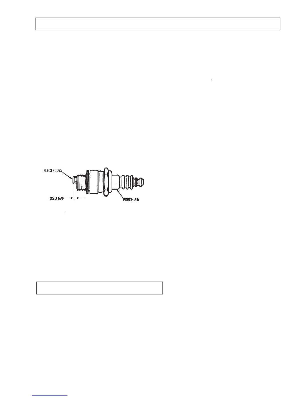
SPARK PLUG
:
1. Check spark plug yearly or every 100 operating hours.
2. Clean around spark plug. Remove and inspect spark
plug.
3. Replace spark plug if electrodes are pitted, burned, or
porcelain is cracked. Use NGK CR5HSB or
equivalent.
4. Check electrode gap with a wire feeler gauge and set
gap at .026” if necessary.
5. Install spark plug and tighten securely.
MUFFLER AND CYLINDER EXHAUST PORTS
The muffl er and cylinder exhaust ports require cleaning
after every 100 hours of operation. For this maintenance
procedure, we recommend that you take your engine to a
Authorized TRAK-STAR Service Center or your
Honda Registered Service Dealer.
COOLING SYSTEM
:
Important: Frequently remove debris from cooling fi ns, air
intake screen, and levers and linkage. This will help ensure
adequate cooling and correct engine speed.
The RailBoss requires minimal maintenance to keep drill in
top working condition.
• Every four to six months or as needed apply a light
coat of grease to the quill and arbor assembly and the
large screw that tightens the handle.
• Keep drill clean.
• Maintain motor as outlined in your Honda motor
operator’s manual.
Maintenance -- Drill
11
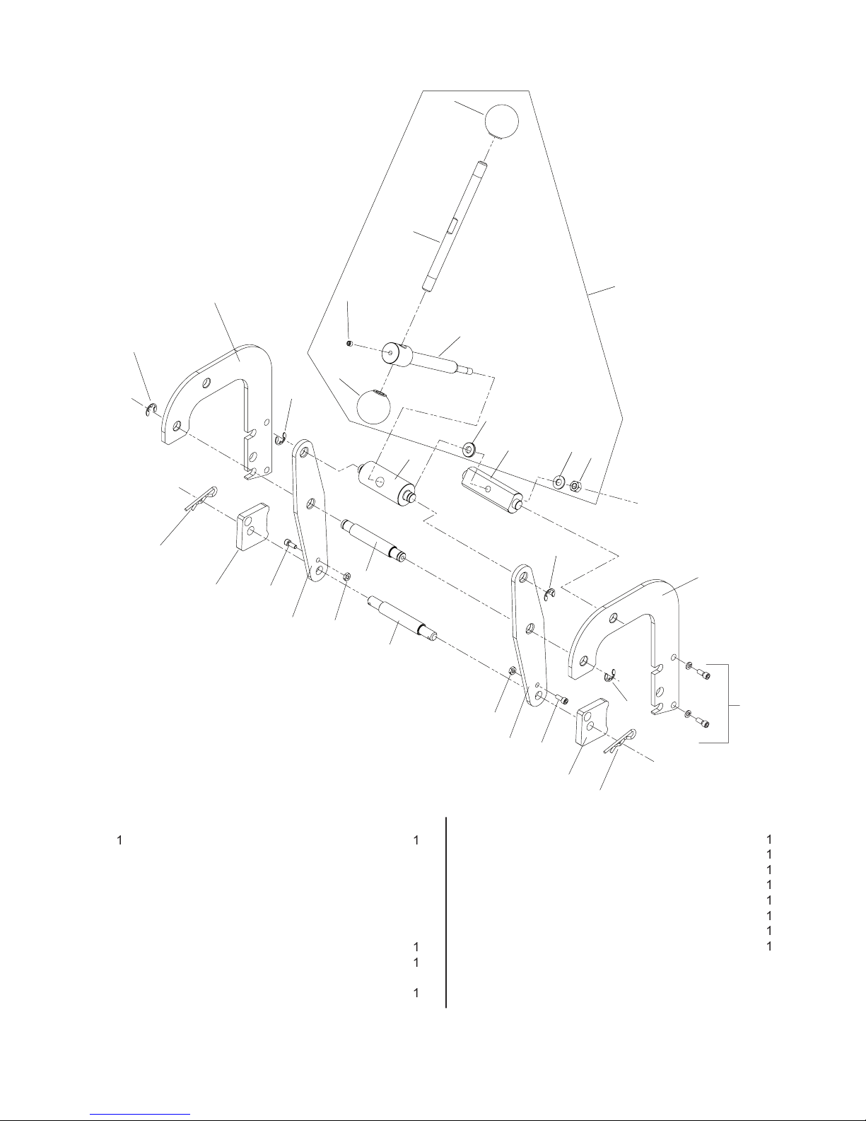
Clamp Exploded View (P/N: 27115)
No.
Part No.
Description
Qty.
No.
Part No.
Description
Qty.
27066
27110
03501
27062
90098
27022
10662
27024
27023
04532
02470
1
2
3
4
5
6
7
8
9
10
11
Retaining Clip Set
Primary Clamp Arm
Hitch Pin
Clamp Pad
Screw #10-24 x 3/4”
Secondary Clamp Arm
Lock Nut - #10-24
Pin
Pin
Knob
Set Screw 1/4-28 x 3/8”
1
2
2
2
2
2
2
1
1
2
1
03522
27027
27026
04782
27025
40074
03563
27080
12
13
14
15
16
17
18
19
Clamp Turn Handle
Clamp Feed Screw
Bushing
Flat Washer
Bushing
Flat Washer 5/16”
Hex Nut 5/16-18
Clamp Handle Assy
1
1
1
1
1
1
1
1
1
2
3
45
67
8
9
1
10
11
12
10
13
14
15
16 17 18
7
5
2
4
3
1
1
6
19
Screws & washers
not included in
clamp assembly

27
88
33
To Motor
(P/N: 27038)
18
35
37
36
27
32
23
26
20
44
24
22
50
51
53
52
1
2
3
4
5
5
6
12
13
17
15
16
14
19
49
25
See Page 11 for Clamp Parts
80*
58
57
57
60
61
59
57
57
58
65 64
56
#80 includes: 62 - 65
#81 includes: 43(2x), gear & shaft
#82 Includes: 43 - 46, gear & shaft
#83 Includes: 43(2x), gear & shaft
#84 Includes: 43(2x), gear & shaft
#85 Includes: 5 - 12
#86 Includes: 57 - 61
#87 Includes: Assy #80 & #86
#88 Includes: 35 - 37
#89 Includes: 1 - 4
#90 Includes: 13 - 17
#91 Coolant Hose Assy (Not Shown)
#92 Rail Clamp Assy
43
43
43
43
43
81*
45
82*
48
83*
84*
11
7
8
9
71
10
85*
43
43
86*
87*
55
34
33
34
28
27
Assemblies
89
90
26
62
92*
38
39
40
42
46
63
70
72
20
54
12
RB28 Housing & Gear
Box Exploded View

Housing & Gear Box Parts
13
No.
Part No.
Description
Qty.
No.
Part No.
Description
Qty.
27019
04919
04809
27059
04815
27046
04794
27047
24160
04793
27048
27051
27029
27028
01153
04859
40038
27060
27005
11050
27064
27063
04838
02071
04810
90027
01121
75313
10624
90028
27054
50038
90077
04836
27035
1
2
3
4
5
6
7
8
9
10
11
12
13
14
15
16
17
18
19
20
22
23
24
25
26
27
28
32
33
34
35
36
37
38
39
FEED HANDLE ASSY
THUMB SCREW
WASHER FLAT
KEY
SCREW
FEED GEAR BEARING
O RING
FEED GEAR SHAFT
RET RING
FLAT WASHER
KEY
FEED GEAR
LOCATING ARM
BRACKET LOCATOR
PIN DOWEL 3/16 X 1/2
SCREW
SCR-SHC 10-32
CARRYING HANDLE
MOTOR HOUSING
SCR-SOC SET 1/4-28
CLUTCH ROTOR
CLUTCH HOUSING
WASHER-SHIM
PIPE PLUG
MOTOR MOUNT
WASHER FLT 1/4 ID
SCR-SHC 1/4-28
SCR-SHC M6
SCR-SHC 1/4-20
WSR-HEL LOCK 1/4”
SUPPORT HANDLE
WASHER-HELI
SCR-BHC 10-32
O RING 1” ID
EJECTOR PIN ASSY
1
1
1
1
3
1
1
1
1
1
2
1
1
1
1
1
1
1
1
1
1
1
1
1
1
1
1
1
1
1
1
1
4
1
1
40*
42
43
44
45
46
48
49
50
51
52
53
54
55
56
57
58
59
60
61
62
63
64
65
70
71
72
27016
04807
24100
27057
04804
27014
27015
27113
40558
40107
40110
04918
04787
27033
27031
04791
04788
04790
27034
40232
02363
27032
04736
04737
05196
24088
04792
COOLANT SEAL
O-RING
BALL BEARING
KEY
BALL BEARING
ENGINE DRIVE SHAFT
DRIVE GEAR/SPINDLE
HOUSING ASSY
SCR-SHC 5/16
WASHER 5/16-HELI
WASHER LOCK 1/2
4 POINT HANDLE
SPRING
PILOT PIN
BRG-NUT
THRUST WASHER
THRUST BEARING
NEEDLE BEARING
QUILL
NEEDLE BRG 40MM
O RING
ARBOR
LIP SEAL
RET RING
TEFLON WASHER
FLAT WASHER
PIN
1
2
1
1
1
1
1
1
4
4
2
2
1
1
1
4
2
1
1
1
1
1
1
1
1
1
1
Assemblies
80
81
82
83
84
85
86
87
88
89
90
91
92
27038
27040
27041
27044
27042
27043
27045
27050
27030
27081
27019
27082
27065
27115
2.5 HP HONDA MOTOR
ARBOR ASSEMBLY
GEAR ASSY
DRIVE GEAR ASSY
GEAR ASSY
GEAR ASSY
FEED GEAR ASSY
QUILL ASSEMBLY
ARBOR & QUILL ASSY
SUPPORT BRACKET ASSY
FEED HANDLE ASSY
LOCATING PIN ASSY
COOLANT HOSE ASSY
CLAMP ASSY
* MUST ALSO PURCHASE #42
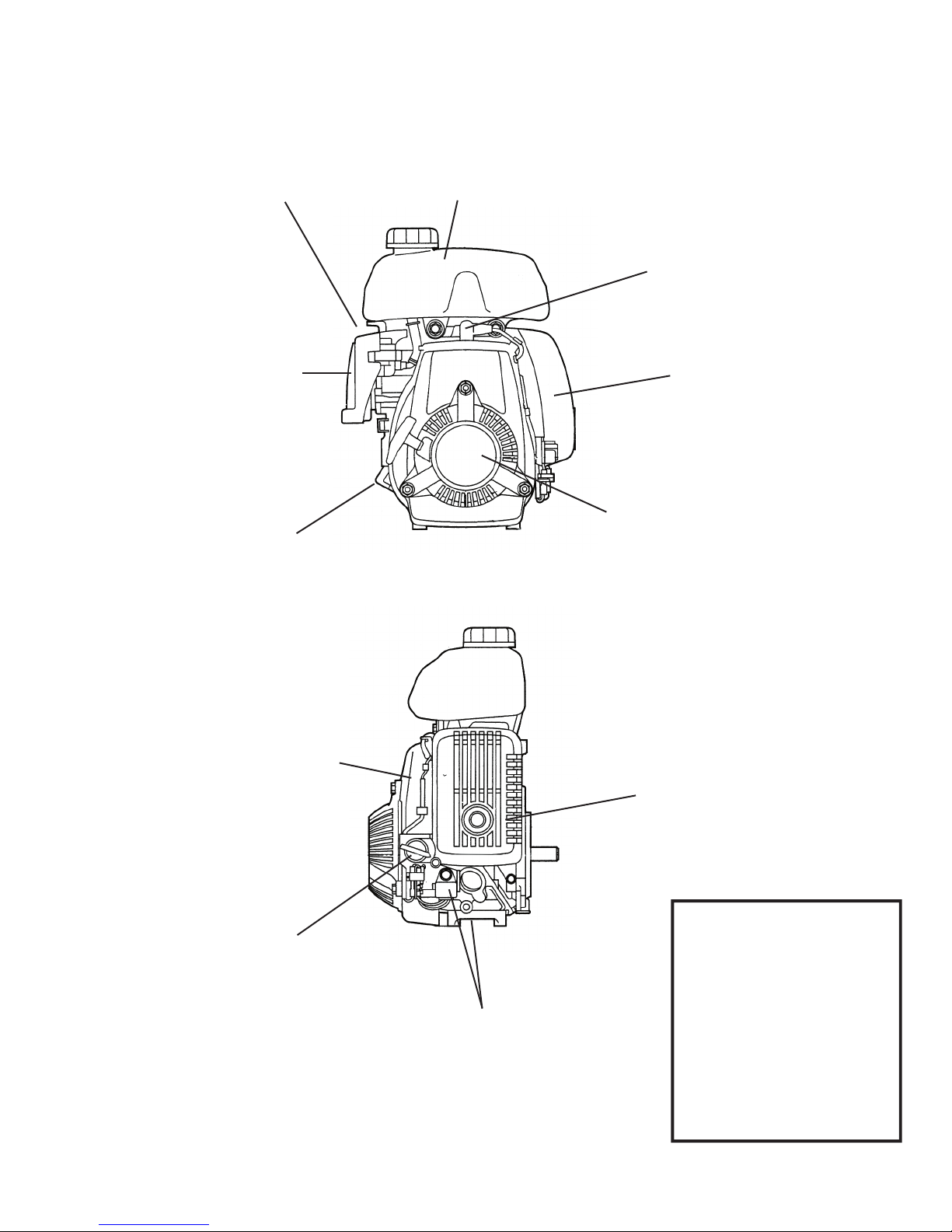
Engine Parts
14
Cover HD5988670
Element HD5988639
Gasket HD5988662
Flange Bolt HD6006084
Carburetor Assy HD6841118
Gasket Set HD3521192
Air Cleaner Housing HD5988647
Back of Cleaner Housing HD5988647
Air Cleaner Guard 27093
Air Cleaner/Carburetor Parts
Starter Parts
Recoil Assy HD5988795
Nut HD0636951
Knob HD5383948
Rope HD5988845
Pulley HD5988829
Recoil Case HD5988803
Muffler Parts
Muffler HD5988720
Muffler Protector HD5988746
Bolts for Protector HD0941096
Spark Arrester HD5988753
Spark Plug
Spark Plug HD5384631
(NGK CR5HSB)
Fan Cover
Cover HD5988779
Long Bolts HD5988969
Short Bolt HD5988977
Coil Assy Ignition HD5988852
Oil Alert
Oil Alert Unit HD5858444
Oil Level Switch HD6005870
(Under Housing)
Gas Tank
Tank HD6005748
Cap HD6673289
Bolt HD2251288
Fuel Tube HD6005771
Fuel Filter HD1452945
Oil Fill
Cap w/ gasket HD6005573
Engine Oil 27091
Switch
On/Off Switch HD2787869
Governor Parts
Governor Arm HD6005672
Governor Rod HD6005680
Governor Spring HD6005698
Throttle Return Spring HD6005706
These parts and others not
listed here are available from
Trak-Star by calling
866-245-3745
Parts and service regarding
Honda Motor ONLY are also
available at your local
Honda Service Center
Motor
Complete Motor 27038

15
Rail & Shoe Data
Railway Association or System Tee Rail
Section (lb.) Section Designation Shoe
Part No.
ASCE - American Society
of Civil Engineers
70 7040 70 AS 701 01906
75 7540 75 AS 753 01907
80 8040 80 AS 800 01908
85 8540 85 AS 851 01909
90 9040 90 AS --- 01910
100 10040 100 AS --- 01911
ARA - American
Railway Association
Type "A" - High Rail for High Speeds
90 9020 90 RA 902 01927
100 10020 100 RA 1003 01928
Type "B" - Lower Rail for Heavy Loads @ Slower Speeds
90 9030 90 RB 905 01908
100 10030 100 RB 1002 01910
AREA - American Railway
Engineering Association
100 10025 100 RE 10025 01894
110 11025 110 RE 1100 01895
112 11228 112 RE 1121 01896
115/11911525 115 RE 115001897
11937 119 RE 1190
130 13025 130 RE 1300 01898
131 13128 131 RE 1311 01899
132/136/141
13228 132 RE 1321
0190213622 136 RE 13637
--- 141 --- ---
133 13331 133 RE 1330 01901
140 --- 140 RE --- 01903
CSX 122 --- 122 CB --- 01918
UP (former C & NW) 100 10035 100 DM 10035 01926
PS - Pennsylvania System
85 8531 85 PS --- 01912
100 10031 100 PS --- 01913
130 13031 130 PS --- 01914
155 15531 155 PS --- 01919
NYC (Dudley) - New York Central &
Hudson River Railroad
105 10524 105 DY --- 01915
127 12723 127 DY --- 01916
PRR - Pennsylvania Railroad 85 8533 85 PR --- 01917

Hougen Manufacturing, Inc.
P.O. Box 2005 • Flint, MI 48501-2005
3001 Hougen Drive • Swartz Creek, MI 48473
Phone: (866) 245-3745 • Fax (800) 309-3299
E-Mail: info@trak-star.com
On-line: www.trak-star.com
OMRB281105 R707 Printed in U.S.A.
© 2007 Hougen Manufacturing, Inc.
Hougen Manufacturing has received the
Association of American Railroads
Quality Assurance Program Certifi cation
Hougen Manufacturing, Incorporated warrants its Trak-Star Rail Drills, Portable Magnetic Drills, Electro-hy-
draulic Hole Punchers for one (1) year and other products for ninety (90) days from date of purchase against
defects due to faulty material or workmanship and will repair or replace (at its option) without charge on any
items returned. This warranty is void if the item has been damaged by accident or unreasonable use, neglect,
improper service, or other causes not arising out of defects in material or workmanship. No other expressed
warranty is given or authorized. Hougen Manufacturing, Inc., disclaims any implied warranty of MERCHANT-
ABILITY or FITNESS for any period beyond the expressed warranty and shall not be liable for incidental or
consequential damages. Some states do not allow exclusions of incidental or consequential damages or limi-
tation on how long an implied warranty lasts and, if the law of such a state governs your purchase, the above
exclusion and limitation may not apply to you. This warranty gives you specifi c legal
rights and you may also have other rights which vary from state to state.
To obtain warranty service, return the item(s), transportation prepaid, to your nearest Factory Authorized
Repair Center or to Hougen Manufacturing, Inc. 3001 Hougen Drive, Swartz Creek, Michigan 48473.
THIS WARRANTY IS IN LIEU OF ANY OTHER WARRANTY, EXPRESSED OR IMPLIED, INCLUDING ANY
WARRANTY OF MERCHANTABILITY OR FITNESS FOR A PARTICULAR PURPOSE.
©
2007 Hougen Manufacturing, Inc.
Commercial / Industrial Limited Warranty
Commercial / Industrial Limited Warranty
FACTORY AUTHORIZED WARRANTY SERVICE CENTERS
Hougen Manufacturing, Inc. Kenbil Service Co.
3001 Hougen Drive 2900 Adams Street B-14
Swartz Creek, MI 48473 Riverside, CA 92504
(866) 245-3745 (951) 689-6633
Photographs and Specifi cations shown are accurate in detail at time of printing. Manufacture reserves the
right to make improvements and modifi cations without prior notice.
Hougen, Hougen-Edge, Trak-Star, and Punch-Pro are propriety trademarks of Hougen
Manufacturing, Inc. Ogura and the Ogura logo are proprietary trademarks of Ogura & Co., Ltd. Honda logo
appears courtesy of American Honda Motor Co.
Table of contents
Other Trak-Star Drill manuals


Popular Drill manuals by other brands


Dynabrade
Dynabrade 53435 Important operating, maintenance and safety instructions

JEI DRILLING & CUTTING SOLUTIONS
JEI DRILLING & CUTTING SOLUTIONS MINIBEAST Operator's manual

Patriot
Patriot AV0108 user manual

Draper
Draper PR812V instructions

Meister
Meister SB500 Translation of the original instructions

Skil
Skil 3070 Original instructions


