TRAMEX Dec Scanner User manual

non-destructive
roof moisture scanner

Introduction..................................................................................................................................2
How the Dec Scanner Works..................................................................................................2
Assembly Instructions..............................................................................................................2
Operating Instructions..............................................................................................................3
• Using the control panel.........................................................................................................3
• Range selection.......................................................................................................................4
• Calibration setting..................................................................................................................4
Conducting a roof survey.........................................................................................................4
Tracing a leak................................................................................................................................5
Types of roofing structure and their more common problems.................................5
Maintenance of the instrument.............................................................................................6
Limitations....................................................................................................................................6
Calibration.....................................................................................................................................6
Warranty.........................................................................................................................................6
Product Development...............................................................................................................7
Safety...............................................................................................................................................7
Technical data...............................................................................................................................7
User Guide
1
TABLE OF CONTENTS

User Guide User Guide
2
INTRODUCTION
Thank you for selecting the Dec Scanner instrument from
Tramex.
The Tramex Dec Scanner is a non-destructive impedance
moisture scanner designed for detecting and evaluating
moisture conditions in roofing and waterproofing systems.
The Dec Scanner has 3 ranges of sensitivity to enable the
surveying of a variety of roof types and roofing depths, and
is equipped to detect moisture in the majority of roofing and
waterproofing systems.
To get the maximum benefit from your Tramex Dec Scanner,
it is suggested that you read this manual to familiarize
yourself with the instrument and its capabilities, before
undertaking any roof investigations.
WHY SHOULD TESTING BE DONE ?
Excess moisture in a roofing and waterproofing system can
affect its performance, reducing thermal resistance values
and energy efficiency, raising energy costs, and eventually
causing structural damage and system failure.
WHEN SHOULD TESTING BE DONE ?
Testing and surveying of roofing systems needs to be
carried out at various stages of the lifetime of the roofing
and waterproofing system:
at installation to ensure roofing quality;
regularly as part of an ongoing maintenance program,
in order to monitor and take remedial action in plenty
of time to prevent major and expensive stripping and
re-roofing;
prior to reparation or re-roofing in order to determine
the cause and extent of damage.
The signals from this instrument will not penetrate
certain types of rubber roofing material such as
some black E.P.D.M and some Butyl Rubber. The
Dec Scanner is not suitable for any roofing with
electrically conductive or metal-faced membranes.
IMPORTANT NOTE
HOW THE ‘DEC SCANNER’ WORKS
The Dec Scanner detects and evaluates the moisture
conditions within roofing and waterproofing systems by
non-destructively measuring the electrical impedance. This is
a method that is very well suited to obtaining comparative
moisture content readings in the many different types of
materials used in the roofing assembly.
The Dec Scanner is a battery powered, electronic instrument,
that generates a low frequency electronic signal. This signal
is transmitted into the material under test via one of the two
electrodes incorporated in the rubber electrode mat, which is
draped on the underside of the instrument. The other
electrode receives the signal that is transmitted through the
material under test. The strength of this signal varies in
proportion to the amount of moisture in the material under
test. The Dec Scanner determines the strength of the current
and converts this to a comparative moisture value. By moving
the Dec Scanner across a roofing surface in a regular pattern,
a continuous reading is obtained, and any areas that contain
moisture can be readily identified.
ASSEMBLY INSTRUCTIONS
Remove the Base Unit from the carry case using the grab
handles.
Check the tightness of the 8 electrode mat retaining
screw fasteners.
To insert the telescopic handle: fully open the flip lock
mechanism, extend the lower part of the handle, insert
the threaded end into the Base Unit and turn clockwise
until tight and secure.
Extend the telescopic handle to the desired height.
Position the meter bracket to the front, ensuring the
arrow is pointing directly down the handle for optimal
infrared communication between Base Unit and Control
Panel Meter. Close and lock the flip lock.
Adjust the hand piece to the desired position.
Remove the Control Panel Meter from the carry case and
clip it onto the meter bracket.
Also included is a folder containing survey sheets and
the warranty card. (This should be completed and
returned to Tramex Ltd, Ireland.)
1.
2.
3.
4.
5.
6.
7.

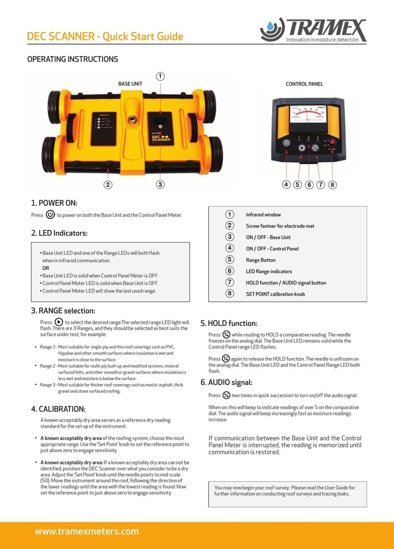
POWER ON: Press to power on both the Base Unit
and the Control Panel Meter.
LED Indicators:
If communication between the Base Unit and the
Control Panel Meter is interrupted, LEDs on both units
will remain solid. The reading is memorized until
communication is restored.
BATTERY LOW indication: When powered on the battery
voltage in the Base Unit and the Control Panel Unit is
measured. If battery level is low:
Base Unit LED will flash for 7 seconds for Base Unit
battery.
Control Panel Unit LEDs 1, 2 and 3 will flash
alternately for 5 seconds for Control Panel battery.
These signals indicate that the battery requires
replacement.
RANGE selection: Press to select the desired Range 1,
2, or 3. The selected range LED will flash. (See below for
Range Selection information.)
Adjust ‘Set Point’ knob, over a known dry area, to read
just above zero to engage meter reading sensitivity. If
the audio signal is ON it will beep. (see Audio Signal
below)
HOLD function: Press while reading to select the
HOLD function when you need to record a comparative
reading. The needle freezes on the analog dial. The Base
Unit LED remains solid while the Control Panel Range
LED flashes.
Press again to release the HOLD function. The Base
Unit LED and the Control Panel Range LED both flash.
AUDIO SIGNAL: Press two times in quick succession
to turn on/off the audio signal. When on, this will beep to
indicate readings of over 5 on the comparative dial. The
audio signal will beep increasingly fast as the moisture
readings increase
3
OPERATING INSTRUCTIONS USING THE CONTROL PANEL METER
1
3
45678
2
BASE UNIT
CONTROL PANEL
1
3
8
4
5
6
7
2
Base Unit LED and one of the Range LEDs will both flash
when in infrared communication
OR
Base Unit LED is solid when Control Panel Meter is OFF.
Control Panel Meter LED is solid when Base Unit is OFF.
Control Panel Meter LED will show the last used Range.
Infrared window
Screw fastner for electrode mat
ON / OFF - Base Unit
ON / OFF - Control Panel
Range Button
LED Range indicators
HOLD function / AUDIO signal button
SET POINT calibration knob
1.
2.
3.
4.
5.
6.
7.
8.

User Guide
4
CONDUCTING A ROOF SURVEY
AUTOMATIC POWER OFF: To conserve battery life the
units will automatically power off after 20 minutes in
the following situations:
If infrared communication is interrupted (e.g. if the
Control Panel Unit is removed from its bracket.)
If either of the units are turned off, the other unit will
timeout.
9.
You may now begin your roof survey. Please read on for
information about Range Selection and further Operating
Instructions.
RANGE SELECTION
The Dec Scanner has an integrated and adjustable calibration
ability allowing for accurate comparative readings. There are
3 Ranges, and they should be selected as best suits the
surface under test, for example:
Range 1- Most suitable for single-ply and thin roof
coverings such as PVC, Hypalon and other smooth
surfaces where insulation is wet and moisture is close to
the surface.
Range 2 – Most suitable for multi-ply built-up and
modified systems, mineral surfaced felts, and other
smooth or gravel surfaces where insulation is less wet and
moisture is below the surface.
Range 3 – Most suitable for thicker roof coverings such as
mastic asphalt, thick gravel and stone surfaced roofing.
CALIBRATION SETTING
A known acceptably dry area should always serve as a
reference location for the set up of the instrument.
On a known acceptably dry area of the roofing system,
where the surface and sub-surface insulation and
components are dry, choose the most appropriate range.
Using the ‘Set Point’ knob, set the reference point to just
above zero to engage sensitivity.
If a known acceptably dry area can not be identified,
position the Dec Scanner over what you consider to be an
acceptably dry area. Adjust the ‘Set Point’ knob until the
needle points to mid-scale (50) to allow for readings of
potentially drier areas. Move the instrument around the
roof, following the direction of the lower readings until
the area with the lowest reading is found. Now set the
reference point to just above zero to engage sensitivity.
In these situations the use of a pin type resistance meter
with insulated pins can help determine moisture condi-
tions and depth.
When conducting a survey it is important to verify the
composition of the roofing assembly, acquire any historical
data as regards its age and performance record, and a
roofing plan drawing. Ensure that surface is clean of debris
and dry of rain or dew etc. Aggregate should be dry and of
uniform thickness.
Information Check List:
Complementary Tramex equipment:
Recording the following information will assist you in
completing a comprehensive roof survey.
Building Name and Number
Date of Survey
Name of Surveyor
Visual Inspection of all Roof Flashings
Visual Inspection of Roof Lights & Openings
Visual Inspection of Vents, Chimneys and other Protrusions
Visual defects and anomalies
The Tramex RWS is a handheld roof scanner for
non-destructive moisture evaluation within the insulation
and thickness of the roof. Working on the same ranges as
the Dec Scanner it can be used in conjunction, allowing for
additional readings at edges, near penetrations, equip-
ment curbs and flashings, and for readings from under-
neath the roof when possible.
The Tramex CMEX II is a handheld digital meter designed
for the non-destructive measurement of moisture
conditions in concrete decks, with applications for the
measurement of moisture conditions in wood decks, as
well as ambient relative humidity and dew-point
conditions.
The Tramex Infrared Surface Thermometer will permit
accurate temperature readings of the roof.
The Roof Survey should be conducted using accessories and
tools as suggested and in accordance with the roofing or
waterproofing system manufacturer’s recommendations or
National Roofing Contractors Association Repair Manual
for Low-slope Roof Systems.

5
Procedure: TRACING A LEAK
Make a sketch of the roof, indicating openings and
protrusions etc.
Select a convenient grid span i.e. 5ft (1,5m) and on the
North/South perimeter, mark 1, 2, 3 etc. while on the
East/West perimeter mark A, B, C etc. Transfer these
grid systems markings to your roof sketch. (Fig 4)
Ambient Relative Humidity, Temperature and Dew-point
readings should be noted before, midway through and at
the end of the survey.
Proceed by moving the Dec Scanner along the imaginary
line A and mark location on the sketch graph paper and
roof surface if desired, when moisture is indicated. N.B
In this mock up test, position A4 is the first point of
moisture contact (Figure 4).
As the survey continues, a moisture profile will build up,
indicating areas which require attention. On single ply
roofing, particular attention must be paid to laps and
seams.
Take additional readings, near penetrations, equipment
curbs and flashings, at edges, as well as other roof areas
commonly identified as areas of possible moisture ingress.
The location and depth of extra-depth insulation, such as in
an over-laid system or tapered insulation, should be
confirmed with a pin-probe resistance type meter.
Should a precise percentage of moisture be required, a
sample can be removed from the site, sealed in a plastic
bag and checked in a laboratory, by weighing, drying and
reweighing, to calculate the exact amount of moisture
present. It is important to also examine the plys of the
roofing felt after taking the test cut, as moisture may be
present between the plys or within the fibre of the felt.
Figure 4. Grid system markings
As moisture penetration into the building can be a consider-
able way from the original point of entry through the
punctured membrane, the Dec Scanner will be found useful
in tracing a leak to its source. (A sloping roof is more likely
to suffer from extended leaks than a flat one).
Calibrate on a known dry area as detailed previously,
using the scale most appropriate to the type of roof.
Take the instrument to the general area above the
internal leak.
Scan the area in an ever widening pattern, until the
source of the leak is located (Fig.5)
TYPES OF ROOFING STRUCTURE AND
THEIR MORE COMMON PROBLEMS.
Built-up-Roofing Systems (BURs): Comprising of 3 or 4
layers of roofing felt, with bitumen adhesive between
each layer. ( Fig.6 ). Problems include:
Mechanical damage from maintenance personnel.
Fissures or cracks in the membrane, caused by
building settlement or expansion and contraction.
Blistering caused by moisture trapped in the roof
system during construction.
Modified Bitumen Systems: This type of material is
either adhesive or heat applied as a single layer system,
or with a base layer of bituminous felt. Sometimes
problems occur on the laps and upstands if material is
not fully sealed during construction.
Single Ply Roofing: Usually applied in welded sheet form,
direct to the insulation. Problems usually occur from
mechanical damage and maintenance personnel,
pin-holes, bird damage and faulty seams during
construction.
Figure 5.
1.
2.
3.

User Guide
6
CALIBRATION
WARRANTY
MAINTENANCE OF THE INSTRUMENT
LIMITATIONS
Warranty claims
Figure 6. Typical Built-Up Roof on metal deck.
Apart from the replacement of the 9V PP3 alkaline batter-
ies, the only maintenance check required is the regular
examination of the electrode mat. Clean with a damp cloth
and soapy solution, but never use solvent to clean the
surface. If damage is identified, the mat should be replaced.
In the event of instrument malfunction, return the instru-
ment immediately to your supplier.
The Tramex Dec Scanner and RWS Roof and Wall Scanner
are not suitable for use on any roofing with electrically
conductive or metal-faced membranes. Metal and other
electrically conductive surface coverings and near-surface
embedded metallic components are not suitable for
surveying with these instruments because of the electrical
conductivity of these materials. Most types of black EPDM
produce false positive readings when tested with this
method due to the material’s high dielectric constant. The
degree to which these false positives need to be factored
out will affect the depth of signal penetration. Aluminum foil
on top-faced insulation or waterproofing membranes give
false positive readings, however liquid-applied aluminum
pigmented emulsified asphalt based coatings do not
normally have a significant effect on the readings.
Requirements for quality management and validation
procedures, such as ISO 9001, have increased the need for
regulation and verification of measuring and test instru-
ments. It is therefore recommended that calibration of the
Dec Scanner should be checked and certified in accordance
with the standards and/or protocols laid down by your
industry (usually on an annual basis) by an authorized test
provider. The name of your nearest test provider and
estimate of cost is available on request. Calibration adjust-
ments should not be carried out by anyone other than
Tramex or their authorized service provider who will issue a
calibration certificate on completion.
Tramex warrants that this instrument will be free from
defects and faulty workmanship for a period of one year
from date of first purchase. If a fault develops during the
warranty period, Tramex will, at its absolute discretion,
either repair the defective product without charge for the
parts and labor, or will provide a replacement in exchange
for the defective product returned to Tramex Ltd. This
warranty shall not apply to any defect, failure or damage
caused by improper use or improper or inadequate mainte-
nance and care.
In no event shall Tramex, its agents or distributors be liable
to the customer or any other person, company or organiza-
tion for any special, indirect, or consequential loss or
damage of any type whatsoever (including, without limita-
tion, loss of business, revenue, profits, data, savings or
goodwill), whether occasioned by the act, breach, omission,
default, or negligence of Tramex Ltd., whether or not
foreseeable, arising howsoever out of or in connection with
the sale of this product including arising out of breach of
contract, tort, misrepresentation or arising from statute or
indemnity. Without prejudice to the above, all other warran-
ties, representations and conditions whether made orally or
implied by circumstances, custom, contract, equity, statute
or common law are hereby excluded, including all terms
implied by Section 13, 14 and 15 of the Sale of Goods Act
1893, and Sale of Goods and Supply of Services Act 1980.
The Warranty card should be completed and returned to
Tramex Ltd, Ireland. A defective product should be returned
shipping pre-paid, with full description of defect to your
supplier or to Tramex at the address shown on the back of
this guide.

7
PRODUCT DEVELOPMENT
SAFETY
TECHNICAL DATA
It is the policy of Tramex to continually improve and update
all its products. We therefore reserve the right to alter the
specification or design of this instrument without prior
notice.
This Users guide does not purport to address the safety
concerns, if any, associated with this instrument or its use. It
is the responsibility of the user of this instrument to
establish appropriate safety and health practices and
determine the applicability of regulatory limitations prior
to use.
Dimensions:
Dec Scanner 30”W x 15¾ “D x 6¼”H
(762mmW x 400mmD x 158mmH)
Carry case 38”W x 20”D 12”H
(940mmW x 508mmD x 305mmH)
Weight:
Dec Scanner 24.6lbs (11.15Kg)
Carry Case 21.9lbs (9.95Kg)
Outer carton & packing 4.4lbs (2.0Kg)
Total Shipping Weight 51lbs (23.16Kg)
Dimensional Shipping Weight 66lbs (30 Kg)
Battery:
Each unit operates with a PP3 9V alkaline battery (supplied).
The Base Unit has a battery life in excess of 72 hours.
The Control Panel Unit has a battery life in excess of 50 hours.
(These times will be greatly extended if Lithium PP3 batteries
are used.)

www.tramexmeters.com
Tramex Ltd.
Unit F, Glencormack Business Park, Kilmacanogue,
County Wicklow, Ireland.
Email:sales@tramexmeters.com
USA (Toll free) & Canada:
Tel: 1800-234-5849
EU & Rest Of World:
Tel:+353 1 681 4450
FIND US ON:
Other manuals for Dec Scanner
1
This manual suits for next models
1
Table of contents
Other TRAMEX Scanner manuals
Popular Scanner manuals by other brands
Epson
Epson Perfection V600 PHOTO Start here
Rollei
Rollei P-S 100 datasheet

Biocentric Solutions
Biocentric Solutions GuadDog owner's manual
Sensorio
Sensorio LZR -S600 user guide
Epson
Epson 4490 - Perfection Photo Important safety instructions
Colortrac
Colortrac SmartLF 4080E Installation & operating instructions
